TU3C-3
RF MIM Capacitors Using High-K A1203 and AlTiO, Dielectrics
S.
B.
Chen, C.
H.
Lai, Albert Chin, J. C. Hsieh*,
and
J. Liu*
Dept. of Electronics Eng., National Chiao Tung Univ., Hsinchu, Taiwan
'United Microelectronics Cooperation, Hsinchu, Taiwan
Abstracf-
Record high capacitance density of 0.5 and 1.0p / c m 2 are obtained for A I 2 0 3 and AITiO, MIM capacitors respectively, with loss tangent < 0.01 and process compatible to existing VLSI back-end integration. However, the AITiO, MIM capacitor has large Capacitance reduction as increasing frequencies. In contrast, the A 1 2 0 3 MIM capacitor has good device integrity of low leakage current of 4.3X1O4 A/cm2, small frequency-dependent capacitance reduction, and good reliability.
I. INTRODUCTION
RF
MIM capacitor is one of the important devices 'for MMIC that is widely used for impedance matching and filtering. However, the area of total capacitors usually occupies a large portion of the whole ICs, because of the required relatively large capacitance value (a few pF) in MMICs and the small capacitance/area. Therefore, it is highly desirable to increase the capacitance per unit area. Besides, other capacitor requirements of low DC leakage current; small frequency dependent capacitance, low loss tangent, and high reliability should also be satisfied simultaneously. To achieve this goal, it is necessary to apply high dielectric-constant (k) dielectrics for RF MIM capacitors because the capacitance density is e&/k and reducing dielectric thickness usually generates undesired high leakage current and loss tangent. Recently, we have published high-k A1203 and La203 dielectrics for possible replacing conventional Si02 in the gate capacitor ofMOSFET [1]-[4]. Several times larger k value than conventional Si02 (k3.9) has been reported and at the same time achieves good gate dielectric integrity. However, the fabrication of high-k MIM capacitors faces the additional challenge from VLSI process integration: the maximum temperature of forming high-k MIM capacitor should not excess 400°C for back-end process integration [SI. In this paper, we report the application of high-k A1203 and AlTiO, for
RF
MIM capacitors. The advantage of AlTiO, capacitor [3] is the increased k value by adding Ti into AI-0 because very high-k of 86 has been reported in Ti02 [6]. Very large capacitance density of 0.5 and 1,0j@/cm2 are measured for AI2o3 and AITiO, MIM capacitors respectively, which is the highest capacitance density reported in literature [7]-[SI. However, significant
capacitance reduction at high frequency is observed for AITiO, MIM capacitors. In sharp contrast, the A1203 MIM capacitor has good integrity of low DC leakage current, small capacitance reduction, low loss tangent, and high reliability that can minimize the size of MMIC substantially and satisfies the VLSI integration requirement.
.
11. EXPERIMENTAL PROCEDURE
The MIM capacitors were fabricated using 4-in p-type Si with resistivity of 5-10 a-cm. Additional 5000
A
thermal oxide was first grown for VLSI back-end process integration. Then coplanar transmission lines [9]-[ 101 with GSG probe were fabricated on oxide-isolated Si substrates using deposited PtiTi bi-layer followed by subsequent patterning. The transmission line also serves as both top and bottom elec6odes of MIM capacitor. Then thin AI or Ti/Al was deposited under high vacuum condition on patterned bottom AI transmission line, followed by subsequent oxidation and annealing to form respective high-k A1203 or AITiO, [I]-[4]. The oxidation was performed only using dry 0 2 because of the strong reaction between oxygen and AI or Ti. However, the maximum temperature is kept only at 400°C for VLSI process integration consideration. Finally, AI is deposited and patterned for both top capacitor electrode and transmission line, and the device area is 50 p x 5 0 p. The A1203 and AITiO, capacitors were measured using HP4284A precision LCR meter at 100 KHz and 1 MHz [3], while the S-parameters were measured by HP85 1OC network analyzer ranging from 200 MHz to 20 GHz [9]-[ lo]. The measured S-parameters are de-embedded from a dummy device [9]-[10] and the high frequency capacitance plus resistance values are extracted using an equivalent circuit model shown in Fig. 4.111. RESULTS AND DISCUSSION
A. Low Frequencies Characteristics
Fig. 1 depicts the C-V characteristics of A1203 MIM capacitors at different frequencies, and a large capacitance
20 I
per unit area of 0.5 pF/cm2 is measured. It can be seen that no obvious reduction of capacitance is observed for frequencies ranging from 100 KHz to 1 MHz, which indicates the excellent qualities of A1203 MIM capacitor at intermediate frequency region.
1.0-
-A120, 1MHz -A-- AI,O, 5OOkHz -+-AI,O, 100kHz
-1.5 -1.0 0.5 0.0 0.5 1.0 1.5
Voltage (V)
Fig. 1. C-V characteristics of the Al20, MIM capacitors measured at the frequencies of 100 KHz, 500 KHz and 1 MHz.
Negligible capacitance reduction can be observed for increasing frequency from 100 KHz to 1 MHz.
Fig. 2 shows the C-V characteristics of AITiO, MIM capacitors at different frequencies, and a very large capacitance per unit area of -1.0 pF/cm2 is measured at
1 OOKHz. However, severe capacitance reduction can be observed in AlTiO, even increasing frequency to 1 MHz. Although AlTiO, capacitor exhibits higher capacitance and dielectric constant than AI2O3, this merit is almost compensated by the capacitance reduction phenomena at
1 MHz. 1.0
-
I 0.5-
0.04 I 0.0 0.5 1 .o 1.5 VoltaeeMFig. 2. C-V characteristics of the AITiO, capacitors measured at the frequencies of 100 KHz and 1 MHz. Very large capacitance reduction is found from 100 KHz to 1 MHz.
Figs. 3(a) and 3(b) shows the J-V characteristics of Alz03 and AlTiO, MIM capacitors before and after
constant voltage stress, respectively. As shown in Fig. 3, the leakage current in A1203 MIM capacitor is only 4.3~10-* A/cm2 which is much smaller than that in AlTiO, MIM capacitor. It is noted that the physical thickness of
A1203 and AlTiO, are the same of 120
A.
The relatively larger leakage current in AITiO, capacitor than in A1203 capacitor may be due to both smaller bandgap and weaker bond related higher defects in Ti-0. This is further confirmed by the larger magnitude of stress-induced leakage current (SILC) in AlTiO, capacitor than that in A1203 capacitor. The small amount of current increase after stress in AI2O3 MIM capacitor suggests the excellent reliability. The relatively large leakage current of AlTiO,MIM capacitor as compared with the AlTiO, MIS gate capacitor on Si [4] may be due to the limited annealing temperature in MIM case because of the VLSI process integration constraint. 10'l lo41 o - N -
I
I II
0.5 voltage 1.0 1.5 10-l0i
0.0 1 0' ioo - e -Afterstress6
10"- 0.N 5ooo8ec3
-
10"- 0.0 ' 0.5 v-M 1.0 1.5@I
Fig. 3. J-V characteristics of (a) Alz03 and (b) AITiO, MIM
capacitors before and after stress. The small change of leakage current in AI203 MIM capacitor after stress suggests the excellent reliability.
B. High Frequencies Characteristics
To investigate the capacitor characteristics of these two dielectrics at RF regime, we have first established the equivalent circuit model for capacitance and loss tangent extraction. As shown in Fig. 4, the shunt C and G are the basic models for high-k capacitor, whereas additional small series R and L represent the parasitic resistance and inductance in the coplanar transmission line used for RF measurements. Notice that the shunt G is originated from the gate dielectric leakage current; in another word, the gate dielectric having higher leakage current will produce larger loss tangent and power dissipation.
o-T-hr-(j---
C
Fig. 4. The equivalent circuit model for capacitor simulation at
RF regime.
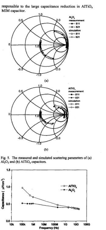
Figs. 5(a) and 5(b) illustrate the measured S-parameters for A1203 and AlTiO, MIM capacitors, respectively. For comparison, the simulated results using equivalent circuit model in Fig. 4 are also shown in these figures. The good agreement between measured and simulated data over the wide frequency range fiom 200 MHz to 20 GHz suggests that the equivalent circuit model shown in Fig. 4 is suitable and reliable for capacitor extraction.
We have further plotted the extracted capacitance from the measured and simulated C-V data and s-parameters shown in previous figures. Fig. 6 demonstrates the frequency-dependent capacitance reduction for AI203 and AlTiO, MIM capacitors. Only a small amount of capacitance reduction for A1203 MIM capacitor is found over the entire frequency range from 100 KHz to 20 GHz. In sharp contrast, very large capacitance reduction is observed for AlTiO, MIM capacitor and the capacitance value gradually reduces to the same value as that of AI203 MIM capacitor. The reason why AITiO, MIM capacitor exhibits severe capacitance reduction may be due to the weak bonded Ti-Ox and is dependent on the process and microstructure. The weak bonded Ti-0, can generate high defect density at low annealing temperature and may be
~
responsible to the I MIM capacitor.
,arge capacitance reduction in AlTiO,
a
+SI1 Z i u r e m e n t-
s21 slmulatlon -n-Sll-
521 1 .o measurement 0 @)Fig. 5 . The measured and simulated scattering parameters of (a) A1203 and (b) AITiO, capacitors.
IOk I W k I M 10M I W M I G IOG loo0
Frequency (W
Fig. 6. The frequency-dependent capacitance for A1203 and AITiO, MIM capacitors. Very large capacitance reduction in
AITiO, MIM capacitor may be defect related because of the
weak Ti-Ox band and low process temperature. (NDL) for their help in the measurement. This work has been supported by NSC (90-22 15-E-009-052) and UMC.
I O ’ I I
I 0 4
0 5 I O 15 20
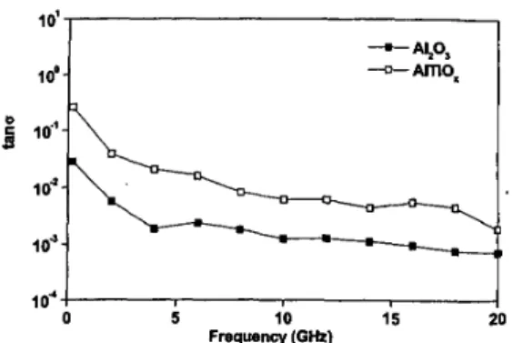
Fig. 7. The kequency-dependent loss tangent for A1203 and AITiO, MIM capacitors. The small loss tangent less than 0.01 suggests the good capacitor performance.
Frequency (GHz)
We have also plotted the loss tangent from the measured and simulated C-V and s-parameters. Fig. 7 shows the loss tangent for Alz03 and AITiO, MIM capacitors. Good RF performance can be evidenced from the low loss tangent for A1203 and AlTiO, capacitors. However, the loss tangent for AITiO, capacitor is near one order of magnitude higher than that for A1203 capacitor because of the larger leakage current in the AITiO, capacitor.
IV. CONCLUSION
To reduce the chip size effectively, it is necessary to reduce the MIM capacitance substantially utilizing thin and high-k dielectrics. Record high capacitance density of 0.5 and 1.0 pF/cm2 are obtained for A1203 and AlTiO,
MIM capacitors respectively, but the AlTiO, MIM
capacitor has large capacitance reduction as increasing frequencies. Besides the high capacitance density, the
AI203 MIM capacitor exhibits low leakage current of
4 . 3 ~ 1 0 ~ ~ A/cm2, low capacitance reduction rate, low loss tangent. The maximum process temperature of 4OO0C makes this technology compatible to current VLSI back- end process.
REFERENCES
[l] A. Chin, C. C. Liao, C. H. Lu, W. J. Chen, and C. Tsai, “Device and Reliability of High-K A1203 gate dielectric with good mobility and low Dit,” Symp. on VLSl Technology, pp. 133-134, June 1999.
[2] A. Chin, Y. H. Wu, S. B. Chen, C. C. Liao, and W. J. Chen, “High Quality La203 and A1203 Gate Dielectrics with Equivalent Oxide Thickness 5-lOA,” Symp. on VLSI
Technology, pp. 16-17, June 2000.
[3] M. Y. Yang, S. B. Chen, A. Chin, C. L. Sun, B. C. Lan, and S. Y. Chen, “One-Transistor PZT/A1203, SBT/A12O3 and BLT/AI2O3 Stacked Gate Memory,” Int. Electron Devices Meeting (IEDM), Washington DC, USA, Dec. 2001. [4] A. Chin, S. B. Chen, K. T. Chan, J. C. Hsieh, M. H. Chang,
C. C. Lin, and J. Liu, “RF Performance Limitation of High- k AITiO, and A1203 Gate Dielectrics,” Int. Workshop on Gate Insulator, pp. 62-63, Tokyo, Japan, Nov. 200 I . [5] Y. H. Wu, A. Chin, K. H. Shih, C. C. Wu, C. P. Liao, S. C.
Pai, C. C. Chi, “The fabrication of very high resistivity Si with low loss and cross talk,” IEEE Electron Device Lett.
[6] S. A. Campbell, D. C. Gilmer, X. C. Wang, M. T Hsieh, H.
S . Kim, W. L. Gladfelter, and T. Yyan, “MOSFET transistors fabricated with high permitivity Ti02 dielectrics,” IEEE Trans. Electron Devices, vol. 44, no. I , [7] C. P. Yue and S. S. Wong, “A study on substrate effects of Silicon-based RF passive components,” IEEE MTT-S Intl. Microwave Symp. Dig., pp. 1625-1628, June 1999. [8] P. Zurcher, P. Alluri, P. Chu, A. Duvallet, C. Happ, R.
Henderson, J. Mendonca, M. Kim, M. Raymond, T.
Remmel, D. Roberts, B. Steimle, J. Stipanuk, S. Straub, T.
Sparks, M. Tarabbia, H. Thibieroz, and M. Miller, “Integration of thin film MIM capacitors and resistors into copper metallization based RF-CMOS and Bi-CMOS technologies,” in Int. Electron Devices Meeting (ZEDM) Tech. Dig., pp. 153-156, Dec. 2000.
[9] K. T. Chan, A. Chin, C. M. Kwei, D. T. Shien, and W. J.
Lin, “Transmission line noise from standard and proton- implanted Si,” in IEEE MTT-S Intl. Microwave Symp. Dig.,
pp. 763-766, June 2001.
[IO] Y. H. Wu, A. Chin, K. H. Shih, C. C. Wu, C. P. Liao, S. C.
Pai, and C. C. Chi, “RF loss and crosstalk on extremely high resistivity (IOk-IMR-cm) Si fabricated by ion implantation,” in IEEE MTT-S Intl. Microwave Symp. Dig.,
pp. 221-224, June 2000. 21, pp, 394-396,2000.
pp. 104-109, 1997.
~
ACKNOWLEDGEMENT
The authors would like to thank