2OMPUTER VISION, GRAPHICS, AND IMAGE PROCESSING 47, 227-242 (1989)
NOTE
A Systolic Algorithm for Extracting Regions
from a Planar Graph
Z E N - C H U N G S H I H
Department and Institute of Information Science, National Chiao Tung University, Hsinchu 30050, Taiwan, Republic of China
R. C. T. LEE
Institute of Computer and Decision Sciences, National Tsing Hua University, Hsinchu 30043, Taiwan, and Academia Sinica, Nankang, Taipei, Republic of China
A N D
S. N. YANG
Institute of Computer and Decision Sciences, National Tsing Hua University, Hsinchu 30043, Taiwan, Republic of China
Received January 6, 1988; accepted January 4, 1989
I n this paper, we describe a systolic algorithm for extracting all of the f u n d a m e n t a l regions in a p l a n a r graph. It takes O(n) computation time and uses O(n) processing elements, where n is the n u m b e r o f edges of the i n p u t planar graph. 9 1989 Academic Press, Inc.
1. I N T R O D U C T I O N
Let us consider Fig. 1. In Fig. 1, there are four regions, as indicated (R4 9 epresents the entire space not occupied by the graph). Suppose we are given all of h e edges of the graph and their geometrical orientation. Can we find all of the 'egions automatically? A similar problem was discussed in [Nie 82]. In their )roblem, we are given a polygon which is not simple and we are asked to produce dl regions formed by the intersecting line segments of the polygon.
In this paper, we shall show that indeed we can. We have designed a systolic dgorithm to produce all of these regions.
This p a p e r is organized as follows: Some definitions and notations are given in ;ection 2. A n overall picture of our algorithm is given in Section 3. Sections 4 and 5 ntroduce the systolic algorithm. Concluding remarks and future research are )resented in Section 6.
2. D E F I N I T I O N S A N D N O T A T I O N S
DEFINITION 1. An edge is a portion of a line having two endpoints.
Let v a and v b be the endpoints of an edge e. This edge e will be representdd by va, %) or (v b, va) and va and v b are called the ending vertices of e. An edge without lirection is called an undirected edge. An undirected edge e = (v~, %) defines two
lirected edges e i = (v a, Vb) and ej = (v b, v,). Let e = (v a, %) be a directed edge.
227
0734-189X/89 $3.00 Copyright 9 1989 by Academic Press, Inc. All rights of reproduction in any form reserved.
228 SHIH, LEE, A N D Y A N G FIG. 1. v 1 R 2 v 9 R 3 v 8 v 7 v 6 v 4 v 5
There are four regions R1, R2, R3, and R 4 in the planar graph.
We define /3 a and /3 b to be the initial and terminal /3ertices of e, respectively. Conversely, e is called the outgoing and incoming edges of v a and v b, denoted as OUTGO(v,,) and INCOM(vb), respectively. For an edge, either undirected or directed, it is said to be incident on its ending vertices.
A path of directed edges is a sequence of directed edges which are linked at their
ending vertices. Let [el, e2,... , ek] denote a path of directed edges where e I =
<Vi, , v i 2 > , e 2 ---- </3i2 , v i a > , . . . , e k = <Vik , Vik+t >. A cycle of directed edges is a path of d i r e c t e d e d g e s [e 1, e 2 . . . em], w h e r e e I = <Vjx , vj2>, e 2 = </312 , vj3 > . . . . , era_ 1 = <Vjm_l, Vj,>, and e m = <vj , vA), where vjo r vjb, for 1 < a < b < m.
DEFINITION 2. A polygon is a dosed plane figure formed by three or more edges.
Since a polygon is realized by a collection of edges, it can be specified by a cycle of directed edges. The cycle may begin with any edge and proceed in clockwise direction. That is, when we move along the cycle of directed edges, the interior of the polygon lies to the right of us.
DEFINXTION 3. A polygon is simple [Sham 78] if and only if no non-consecutive edges intersect and consecutive edges intersect only at the ending vertices.
DEFINITION 4. The area which consists of a simple polygon and its interior is called a region.
Consider Fig. 1. The polygon [<vl, v2>, <v2, v8>, <v 8, v9>, <v 9, vt0>, (vx0, Vl> ] and its interior form region R t. The polygon [(v2, v3>, (v3, v4>, <13 4, V5>, <V 5, /-)6>,
<v6, v7>, <v7, Vs>, (vs, v2> ] and its interior is also a region which is the union of regions R 2 and R 3. We shall say that the region which is not the union of other regions is a fundamental region, such as R 1, R 2 and R 3 in Fig. 1. We specify a
ALGORITHM FOR EXTRACTING REGIONS 229 region to be the same as specifying a polygon. The difference between a polygon and a region is that a polygon is a cycle of directed edges, but a region is an area.
DEFINITION 5, Let there be two edges ea = (v~: vi2) and e b = (0i2, via ). Let us assume that when we sweep from e~ to e b in the counterclockwise direction, we encounter no other edges incident on v;2. Then the area comprised by e~ and e b is a
wedge between e a and eb, denoted as (vi: vi2, vi3 ). The wedge (via, vi2, 0 i ) is said to
be associated with vi.
By the definition, if there are k edges incident on a vertex v, there are k wedges associated with v, Since an edge is incident on its two ending vertices, there are 2n wedges formed by an n-edge planar graph.
Let w = (v~: v~2, 0i3 ) be a wedge which is comprised by ea = (v;: vi2 ) and
e b = ( v i : v~3). We define e a and e b to be the back and front edges of w, denoted as
BE(w) and FE(w), respectively. Two wedges w x and w 2 are said to be contiguous if
w 1 = (via , vi2 , v i ) and w 2 = (vi2, vi: vi, ). For two consecutive wedges Wl and w 2,
there is a common edge, e -- (vi2, 0i3 ), shared by them, i.e., FE(Wl) = BE(w2). We shall define w 1 and w 2 to be the back and front wedges of e, denoted as BW(e) and FW(e), respectively.
Since a fundamental region contains no other regions, it is more appropriate to describe a fundamental region by a sequence of contiguous wedges. Let R = [ e l , e 2 . . . e k ] be a fundamental region, where e I = (t31, o 2 ) , e 2 = ( 0 2 , 0 3 ) . . . . , ek = (Vk, Or)- Then R can also be represented as [w 1, w 2 .. . . . w~], where w 1 = (vl, v2, v3), w 2 = (02, v 3, v4) . . . w k = (vk, vt, v2). From the above discussion, a se- quence of wedges [w 1, w 2 .. . . , win] defines a fundamental region if and only if w i and
wi+ 1 a r e contiguous, for i --- 1, 2 . . . m - 1, and w m and w 1 are also contiguous.
3. AN OVERALL PICTURE OF THE REGION EXTRACTION ALGORITHM In this section, we shall try to present an overall picture of our region extraction algorithm,
The input of our algorithm is a set of undirected edges. To extract regions, we must perform two tasks:
(1) Find ~ of the wedges. (2) Group the wedges into corresponds to a region.
sequences such that each sequence of wedges
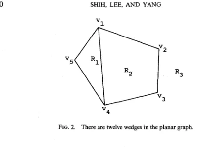
Let us explain this informally by an example. Consider Fig. 2. Since there are six edges in this planar graph, by the definition, there are twelve wedges formed. All the wedges will be found to be (05, 01, 04), (04, vl, v2), (02, vl, os), (01,
02, 03), (03, 02, 01),
(v2, 03, v4), (v4, v3, v2), (v3, v4, vl), (01, v4, 05), (v5, v4, v3), (01, v5, v4), and (v 4, v 5, Vl). After finding all of the wedges, our algorithm will then group them into the following sequences:S~ : [(v5, vl, 04),(vl, v4, 05),(v4, v5, vO]
$2 : [(v4, vl, vD,(vl, v2, v3), (v2, v3, v4), (v3, v4, 01)]
230 SHIH, LEE, AND YANG v 1
v 5 ~
v2
R
2
3
v
4
R 3FIG. 2. There are twelve wedges in the planar graph.
It can be easily seen that each sequence of wedges corresponds to a fundamental region. The following table gives the one-to-one correspondence relationship:
$1: R 1 $2: RE S 3 : R 3.
In the following section, we shall explain how we can find all of the wedges by examining the input edges.
4. PHASE ONE: A SYSTOLIC ALGORITHM TO FIND WEDGES
The principle to construct wedges is quite simple. Consider Fig. 3. There are four edges incident on 01 . Note that the edges mentioned in this section are undirected. Let us sort these four edges according to their angles with respect to the horizontal line passing through 01. We have (v,, v2) < (vl, v3) < (01, 04) < (vl, 05). After these edges are sorted, we can consider these edges as forming a cycle by logically linking the last edge to the first one. Then, each pair of consecutive edges in this cycle forms a wedge.
V
3
V
2
V
4
V
5
FIG. 3. There are four edges incident on v 1.ALGORITHM FOR EXTRACTING REGIONS 231 In general, let e i and ei+ x be a pair of consecutive edges. Let v b be the ending
vertex common to both edges. Let v a and v c be the ending vertices other than v b
which appear in e i and e~+l, respectively. Then e; and ei+ 1 are considered to form
the wedge (Va, Vb, Vc). For the above sorted sequence of edges, the following wedges are formed: (v2, vl, v3), (v 3, v 1, v4), (v4, vl, vs), and (vs, vl, v2). The last wedge is formed by combining the last and the first edges.
Given a planar graph, let E ( o ) denote the set of edges incident on a vertex v. To find the wedges associated with v, we may sort E ( v ) according to their angles with respect to the horizontal line passing through v. We then combine each consecutive pair of edges in the sequence to form wedges. The last edge is also combined with the first edge in the sequence. Let IE(v)l denote the number of edges incident on v. Then the total number of wedges formed is [E(v)l-
Actually, we do not have to separate the edges into groups and sort edges within each group. As shown below, we may sort all of the edges once and for all by the following rules:
(la) Duplicate every edge. If an edge is incident on v i and vj, then one edge is labeled with tag i and the other edge is labeled with tag j. Thus, each edge is now labeled with a tag.
(lb) The precedence-relation between two edges is defined as follows:
(a) If two edges have the same tag, e i < e j if the angle between e i and the horizontal line is smaller than the angle between e j and the horizontal
line.
(b) If two edges have two different tags, then e i < ej if the tag associated with e~ is smaller than the tag associated with e j .
Using the above rules, duplicated edges of a planar graph can be sorted into a sequence. Note that in the resulting sorted sequence, edges labeled with the same tag will be grouped together. A linear scanning over all of the edges will produce all of the wedges.
Let us consider Fig. 4 which contains the same planar graph in Fig. 2. The input edges after the duplication process will be as follows:
(01, 02) 1, (01, 02) 2, (02,/33) 2, (02,/33) 3, (/33,/34) 3, (/33,/34) 4, (/31,/3,) 1, (/31, v4) 4, (vl, vs) 1, (01,/35) 5, (/34, vs) 4, and (/34,/35) 5.
The superscripts of edges in the above sequence are the tag values. The sorting process will produce the sequence:
(01,/35) 1, (01,/34) 1, (/31,/32) 1, (/31, 02) 2, (02,/33) 2, (/32,/33) 3, (/33,/34) 3, (V3, 04) 4, (/31' /34) 4, (/34, /35) 4, (/31, /')5) 5, and (/34, vs) 5.
A linear scanning over the sorted sequence will now take place to produce all of the wedges by using the following rules:
(2a) Within every group of edges with the same tag, combine every pair of consecutive edges.
(2b) Within every group of edges with the same tag, combine the last edge with the first edge.
232
FIG, 4,
SHIH, LEE, AND YANG
V 1
v 4
There are 12 edges generated after the edge duplication process.
In our wedge-finding algorithm, we exploit the zero-time sorter [Lee 81; Mir 83] with a slight modification to perform the edge sorting process. There are n processing elements, which are controlled locally and named as PE 1, P E z , , . . , PE, from left to right.
In addition to the sorter, we shall attach a special cell S in front of the input/output cell of the sorter as shown in Fig. 5. In the input phase of sorting, each edge should pass through cell S and be duplicated. Then, the edges leave this cell and enter the sorter one by one. Therefore, there are 2n edges entering the sorter. In the output phase of sorting, the Sorted sequence of edges should be scanned by this cell where the consecutive edges are merged to form wedges according to the rules discussed before. That is, this special cell ~ performs two functions, it duplicates edges and attaches tags to them before they are fed into the sorter. It later examines edges coming out of the sorter and merges consecutive ones and also the last and the first in the ~ame group to form wedges. Finally, there are 2n wedges constructed, where n is the number of input edges. Let these 2n wedges be denoted as wl, Wz,.,. , w2,.
In this phase, there are 2n edges fed into the zero-time sorter. By [Mir 83], the time spent by the sorter is
O(n).
The special cell S is operated parallel with the sorter. In the input phase of sorter, cell S scans and duplicates each edge in one time unit. Therefore, the total time complexity of phase one isO(n)
and takesO(n)
processing elements in the sorter.5. PHASE TWO: A SYSTOLIC ALGORITHM TO EXTRACT REGIONS
In Section 4, we showed a systolic algorithm to find all of the wedges of a planar graph. In this section, we shall show how the wedges can be combined to form regions.
S o r t e r
N N N --- [l]
A L G O R I T H M F O R E X T R A C T I N G R E G I O N S 233 In our phase-two algorithm, we use a linear systolic array which consists of 2n + 1 processing dements, where n is the total number of edges of the planar graph. The input of our phase-two algorithm is the set of wedges w l , w 2 . . . . , w 2 , ,
which is the output of our phase-one algorithm. This set of wedges define m regions R1; R z , . . . , R m. Let [Ri[, i = 1, 2 . . . . , m , denote the number of wedges of R i. As explained in Section 3, a sequence of wedges [Wal, Wa2 . . . . , W j define a region if and only if wa, and Wai+l are contiguous for i = 1 to k - 1 and wak and w~a are also contiguous. Let wi, j denote a wedge of R r Let us assume that wi, j a n d wi, j + 1 a r e
contiguous for j = 1 to I R i t - 1 and Wi, la,I a n d wi, 1 are also contiguous. Our algorithm will accept a set of wedges wl, w2,..., WE, and output a sequence of
w e d g e s a s f o l l o w s : Wl,1, Wl, 2 . . . . , w l , iRd, W2,1, w2,2, . . . , W2, IR21 , . . . , W i n , l ,
Wm, 2 . . . Wm, iRmr It should be obvious, that in the output sequence, each subse- quence corresponds to a region.
Initially, the set of wedges w 1, WE,..., w2, are fed into the systolic array one by one from left to right, such that w, will be stored in PEi. Then, we shall arrange the wedges into the output sequence. That is, the wedges of each R, are placed in continuous processing elements and the wedges in each pair of neighboring process- ing dements are contiguous if they belong to the same region.
Our Phase two algorithm consists of the following four major steps:
Step 1. Feed the set of 2n wedges wl, w 2 , . . . , w2, into the systolic array one by one from left
to right, such that w i will be stored in PE r
S t e p 2. Find wiA , for i = 1,2 . . . m. Then delete the back edge, BE(w/A), of wi, 1.
S t e p 3. Label all of the wedges in such a way that two wedges have the same label if and only
if they are in the same region. And, assign a sequence number to each wi, j such that the sequence number of wi, j is j.
S t e p 4. Arrange the wedges so that they can be outputted in the following sequence:
wt. 1, Wl.2, ... Wl, i/~x I, w2,1, W2,2,..., W2.1R21,..., Win, l, Win, 2 , . . . , W,n. tRml, where Wi, j a n d wi, j+ 1 are contiguous, for i = 1,2 . . . m and j = 1,2 . . . [R~], and wi.lu,i a n d wiA are also contiguous, for i = 1,2 . . . m.
Step 1 is rather simple. There are 2n + 1 processing elements, labeled as PE 1, P E 2 , . , . , PE2,+I from left to right. We input the wedges w l , w 2 . . . w 2 , one by one from left to right and w~ will be stored in PE;, for i = 1 , 2 , . . . ,2n. PE2,§ is essentially a buffer area and its function will be explained and made clear later.
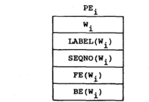
Inside each PEi, i = 1, 2 , . . . , 2n we shall store five pieces of data as shown in Fig. 6. Except w~, which is stored in Step 1, the others are created by each PE r LABEL(wi) is the label of w r SEQNO(w~) is the sequence number of wi. LABEL(w/)
P E . 1 W. 1 LABEL (W i ) SEQNO (W i ) FE(W i) BE (Wi)
234 S H I H , L E E , A N D Y A N G
and SEQNO(wi) will be initialized to be i and 1, respectively, for all wi's. FE(w~) and BE(w~) are the front edge and the back edge of wi, respectively.
In the following paragraphs, we shall first introduce Step 2. Basically, we use a labeling scheme to identify each wi,1 for i = 1, 2 , . . . , m. The basic principle of the labeling can be described below:
(3a) w 1 is labeled with 1.
(3b) For 1 < i < 2n, if there exists a j, j < i, such that wj and w~ are in the same region, then label w~ as wj is labeled; otherwise, label wi with i.
For example, imagine that we have wedges wl, w 2 . . . . , ws, where Wl, ws, and w 6 belong to one region, w2, w3, and w 7 belong to one region, and the rest of wedges to another region. Then our labeling process will label the wedges as follows:
w~ L A B E L ( ~ )
W 1 W 2 W 3 W 4 W 5 W 6 W 7 W 8
1 2 2 4 1 1 2 4
Step 2 consists of three basic steps. Step 2a labels each wedge in such a way that two wedges will be labeled the same if and only if they belong to the same region. Step 2b identifies the first wedge wi, 1 of region i for each i. Step 2c then eliminates the back edge of wi, 1.
Let e 1, e 2 . . . . , e2n be the set of directed edges of the input planar graph. In Step 2a, we feed each ei to the linear systolic array. Each wj. is labeled j initially. After it enters PE2n+I, it will have found the back wedge and the front wedge of e v For instance, for edge (2, 3), let its back wedge be (1, 2, 3) and its front wedge be (2, 3, 4). Let the label of (2, 3, 4) be initially greater than that of (1, 2, 3). Then, as edge (2, 3) travels back through the systolic array, it will change the label of (2, 3, 4) to the label of (1, 2, 3).
But, we have another problem. Consider wedges (1, 2, 3), (2, 3, 4), and (3, 4, 5). suppose edge (2, 3) enters the systolic array before edge (3, 4). Suppose (1, 2, 3) is labeled as 1. (2, 3, 4) will be labeled 1 as we discussed in the above paragraph. But, how can the label of (3, 4, 5) be labeled to 1 also? This is accomplished as follows: (a) Case 1. Edge (2, 3) arrives at the processor holding (2, 3, 4) as it travels back before edge (3, 4) arrives as it travels forward. In this case, the label of the wedge (2, 3, 4) will be changed by edge (2, 3) to 1. Later, edge (3, 4) arrives at this processor holding (2, 3, 4). It will identify (2, 3, 4) as its back wedge and also it will identify (3, 4, 5) as its front wedge. Besides, it notes that the label of (2, 3, 4) is 1. As it travels back, it will then change the label of (3, 4, 5) to 1.
(b) Case 2. Edge (2, 3) arrives at the processor holding (2, 3, 4) as it travels back after edge (3, 4) arrives as it travels forwardly. In this case, edge (3, 4) will identify (2, 3, 4) as its back wedge and it notes the label of (2, 3, 4). Later, edge (3, 4) will encounter edge (2, 3) at a processor on the right of the processor holding (2, 3, 4). The label of (2, 3, 4) traveling with edge (3, 4) will be changed by edge (2, 3) to 1. As edge (3, 4) travels back, it will then change the label of (3, 4, 5) to 1. Through the above mechanism, we can label all of the wedges such that they are labeled the same if and only if they are in the same region. This is the main task of Step 2a.
A L G O R I T H M F O R E X T R A C T I N G R E G I O N S 235 eo 1 LABEL(FW(ei)) LABEL(BW(ei)) PEj W. 3
LABEL (Wi) SEQNO (W i )
BE (Wj) FE (Wj) MIN (ek) e k MAX(e k)
FIG. 7. Edges ei and e k may be entering from the left and right of PEj, respectively.
In Step 2b, each processor PE i checks the label of the wedge it holds. If the label of the wedge is also i, then this wedge is identified as the first wedge of a region.
In Step 2c, each PE k which holds wi, x eliminates the back edge of wi, 1.
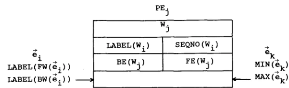
To label each wj, for j = 1 to 2n, we have to input the set of directed edges el, e2,... , e2n one by one from left to right into the systolic array, ei is fed into the systolic array at an interval of every two time steps. The reason will become clear later. For each e~, the following parameters travel together with e~: LABEL(FW(ei)) and LABEL(BW(ei)). Initially, LABEL(FW(ei)) and LABEL(BW(ei) ) are set t o null. As ej enters PE2,+I , we shall have two parameters attached to e/MIN(e~) and MAX(e/). MIN(ei) and MAX(e;) will be explained later.
In the systolic array, e~ and the associating parameters travel from left to right and the movement takes place at an interval of every time step. As soon as e i enters PE2,+I , all of the parameters have been updated. Then, e i will travel from right to left. Again, the movement takes place at an interval of every time step. Thus, at PEj, ei may be entering from the left and e k may be entering from the right as shown in Fig. 7. In Step 2a, the value of SEQNO(wj) is not updated.
The operations inside PEj, 1 < j < 2n, is summarized as follows: (4a) If FE(wj) = ei, then LABEL(BW(e~)) ".= LABEL(wj). (4b) If BE(wj) -- e~, then LABEL(FW(e~)) .'= LABEL(wj).
(4c) If LABEL(BW(e~)) -- MAX(ek) , then LABEL(BW(ei)) := MIN(ek). (4d) If LABEL(FW(ei) ) = MAX(ek) , then LABEL(FW(e~)) .'= MIN(ek). (4e) If LABEL(wj) = MAX(ek) , then LABEL(wj) .'= MIN(ek).
In PE2,+I , if e~ arrives, then let MIN(e~) be the minimum of LABEL(FW(e~)) and LABEL(BW(ei)) and MAX(e~) be the maximum of LABEL(FW(ei)) and LABEL(BW(e,)).
Now, let us consider a simple example. There are five wedges in the systolic array. The whole process of entering (2, 3) and (3, 4) is shown in Fig. 8. In this example, when (2,3) arrives at PE 1 and PE3, the parameters LABEL(FW((2,3))) and LABEL(BW((2,3))) are set according to operations (4a) and (4b), respectively. When (3,4) arrives at PE 3 and PE4, the parameters LABEL(FW((3,4))) and LABEL(BW((3, 4))) are set according to operations (4a) and (4b), respectively. At time step 7, (2, 3) and ( 3 , 4 ) encounter in PE 5 and the parameter LABEL(BW((3, 4))) of (3, 4) is updated according to (4c). At time steps 9 and 10, the labels of (2, 3, 4) and (3, 4,1) are updated according to (4e).
236 PE 1 SHIH, LEE, A N D Y A N G PF~ PE 3 PE 4 P~
P~
t =1 (1,2,3) <112> I <2, 3>, <2, 3> A A (4,1,2) <411> <1, (2,3,4) 2> <2,3> <3,4> (3,4,1) <314>]<4, 1> (3,2, 1) 5 <3, 2>]<2, 1> t=2 (1,2,3) i <1,2> <2,3~ (4,1,2) <4,1> <1,2> <2, 3> & i (2,3,4) <2, 3> <3, 4> (3, 4, 1) <3,4> <4, 1> (3,2,1) <2, 2> <2, 1> t---3 (1,2,3) <112>] <2, 3~" <3, 4> A A (4,1,2) (2,3,4) <4,1 <:1,2> <2,3> <3,4> <2, 3> A 1 (3,4, 1) <3,4> <4, 1> ( 3 , 2 , 1 ) t=4 (1,2,3) <112>1<2,3~ (4,1,2) (2,3,4) (3,4,1) <4,1><1,2> <2,3><3,4> <3,4><4,1> <3,4> <2,3> A 3 A 1 (3,2,1)<312>1<2,1>
t=5 (1,2,3) <a :2>1 <2, 3- (4,1,2) (2,3,4) (3,4,1) <4,!><1,2~ <2,3><3,4> <3,4><4,1> <3,4> A A (3,2,1) <372>1 <~, 1> <2,3> 3 1 W :FIG. 8. A n example o f the labeling scheme to find all i,1 s.From the above example, it is easy to see why e i is fed into the systolic array every two time steps, In order to ensure operations (4c) and (4d) to be performed, ei and e k should encounter in some processing element. Only by feeding ei every two time steps can achieve this purpose.
When the above labeling process is completed, we can easily identify W~,l, for i = 1, 2 . . . m. Then, we shall clear the value of BE(wi.1).
In the f o n o ~ g paragraphs, we shall discuss Step 3. Before starting Step 3, each PEg should initialize LABEL(w/) with the value i, again.
Basically, Step 3 consists of the labeling operation and the sequencing operation. The basic principle of labeling is the same as that of Step 2. The sequencing operation is to assign a sequence number to each w~, for i = 1, 2 , . . . , 2n. The basic principle of sequencing is described below:
(5a) The sequence number of wl is 1.
(5b) For 1 < i < 2n, if there exists a j, j < i, such that w / a n d w i are in the k levels
r=
same region and w , = W ( F E ( . . . F W ( F E ( w j ) ) . . . ) ) , then SEQNO(w~) is set to
A L G O R I T H M F O R E X T R A C T I N G R E G I O N S 237
t=6
t---7
(1,2,3) (4,1,2) (2,3,4) ~,2> <2,3><4,1><1,2>
4>
(1,2,3) (4,1,2) (213,4)1 [
2 t
<213><3,
d,2> <2,3> <4,1> <:I,2> 4> (3,4,1) <314> <4, 1> <:3,4> A 3 ( 3 , 4 , 1 ) <314> <4, 1:(3,2,1)
<312> <2,1;
I
<2, 3> 3 1 ( 3, 2, 1 ) <312> <2, 1> <3,4> <2,3; 4 1 3 3 t ~ (1,2,3) <3-1,2>I<2,
3> (4,1,2) <411>1<1,2> (2, 3,4) <2, 3> <3, 4> (3,4,1)<3~4 >I <4,
I> <2,3>
i
3
(3,2, 1) 5 <3, 2> <1,2>1 <3,4> 4 1 t=9 (1,2,3)<11, 2>I<2,
3> (4, 1, 2) <4,1 <1,2> (2,3,4) <213> <3, 4> <2,3> 1 3 (3,4,1)<3,4 <4,1>
(3,2,1) <312> <2, 1:~ <3, 4> 1 4 t =I0 t=ll t=12t=13
(1,2,3) <21 ,2>[<2,
3> (1,2,3) <112>1<2,3> <2,3> 1 3 (4,1,2) (2, 3,4) <2, 3> 1 3 (4, 1,2) (2,3,4)o:,>
~ o:3>Io,,
( 3 , 4 , 1 ) 1<314>1<4, 1> <3, 4> 1 4(3,2,1)
<3, 2 <2, 1> (3,4, l) (3,2,1) <3,4><4,1.: <3,2 <2,1> (1,2,3)11
<1,2> <2,3> (1,2,3) 112> <2,3> <3,4> 1 4(4,1,2) I
<411>1<1,2> <3~4> (2, 3, 4) 1 [ ]1 1 [ 1 1 (3,4, 1) 1i
<2, 3> <3, 4:, <3,4><4,1 (2,3,4) 51(3'2'1) t <3, 2> <2, l (4, 1,2) (3,4, 1) (3,2,1) (1,2,3) (4,1,2) (2,3,4) (3,4,1) (3,2,1) " <3, 2> <2, 1 > t=14 <1,2> <2,3> 1> FIG. 8--Continued238 SHIH, LEE, AND YANG
For example, imagine that we have wedges w~, w 2 . . . Ws, where w~, w 5, and w 6 belong to one region, w 2, w 3, and w 7 belong to one region and the rest of wedges to another region. Moreover, w 6 = FW(FE(wl)), w 5 = FW(FE(FW(FE(wl))) ), w 3 = FW(FE(w2)), w 7 = FW(FE(w3) ) and w s = FW(FE(w4)). Then, the result of the sequencing process is:
w~ SEQNO(w~)
Wl WE w3 W4 W5 W6 W7 W8
1 1 2 1 3 2 3 2
Initially, each w i is stored in PE;. Then the set of directed edges el, e 2 . . . e2n are fed into the systolic array one by one from left to right again. Each ei is fed into the systolic array at an interval of every two time steps. A f t e r i t enters PE2,+I, it will have found the back wedge and front wedge of e r For instance, for edge (2, 3), let its back wedge be (1, 2, 3) and its front wedge be (2, 3, 4). Suppose that the label of (2, 3, 4) is greater than that of (1, 2, 3). Later, edge (2, 3) will travel back through the systolic array. We shall change the label of (2, 3, 4) to the label of (1, 2, 3) and change the sequence number of (2, 3, 4) to the sequence number of (1, 2, 3) plus one. Consider wedges (1, 2, 3), (2, 3, 4), and (3, 4, 5). Let edge (2, 3) enter the systolic array before edge (3,4). Suppose (1, 2, 3) is both labeled and sequenced as 1. (2, 3, 4) will be labeled 1 and sequenced 2 as we discussed in the above paragraph. To label (3, 4, 5) to 1 is the same as in Step 2. But, how can the sequence number of (3, 4, 5) be changed to 3? This is accomplished as follows:
(a) Case 1. Edge (2, 3) arrives at the processor holding (2, 3, 4) as it travels back before edge (3, 4) arrives as it travels forward. In this case, the sequence number of the wedge (2, 3, 4) will be changed by edge (2, 3) to 2. Later, edge (3, 4) arrives at this processor holding (2, 3, 4). It will identify (2, 3, 4) as its back wedge and also it will identify (3, 4, 5) as its front wedge. Besides, it notes that the sequence number of (2, 3, 4) is 2. As it travels back, it will then change the sequence number of (3, 4, 5) to 3.
(b) Case 2. Edge (2, 3) arrives at the processor holding (2, 3, 4) as it travels back after edge (3, 4) arrives as it travels forward. In this case, edge (3, 4) will identify (2, 3, 4) as its back wedge and it notes the sequence number of (2, 3, 4). Later, edge (3, 4) will encounter edge (2, 3) at a processor on the right of the processor holding (2, 3, 4). The sequence number of (2, 3, 4) traveling with edge (3, 4) will be changed by edge (2, 3) to 2. As edge (3, 4) travels back, it will then change the sequence number of (3, 4, 5) to 3.
Through the above mechanism, we can set the sequence number of each wi, j, for i = 1 , 2 , . . . , m and j = 1,2 . . . [Ria, to j.
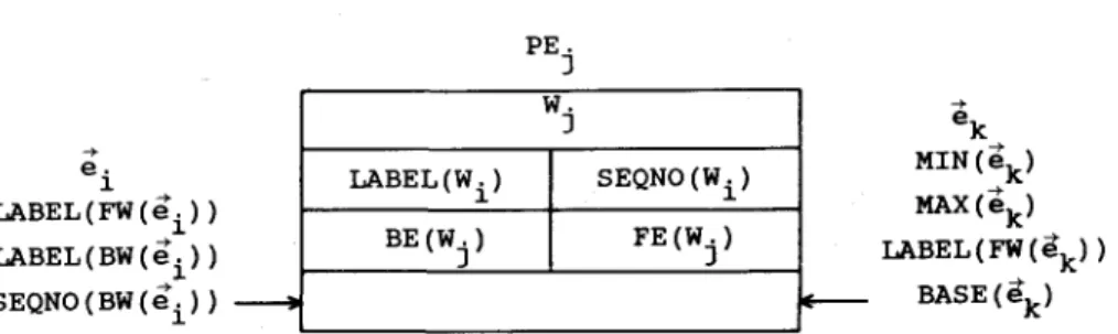
For each ei, the following parameters travel together with e;: LABEL(FW(ei)), LABEL(BW(ei) ), and SEQNO(BW(e,)). Initially, LABEL(FW(ei)), LABEL(BW(ei)), and SEQNO(BW(e;)) are set to null. As e i enters PE2n+I, we shall have four parameters attached to ei: MIN(ei), MAX(ei) , LABEL(FW(ei)), and BASE(ei). BASE(ei) will be explained and made clear later.
In the systolic array, e i and its associating parameters travel from left to right and the movement takes place at an interval of every time step. As soon as e i enters PE/n+~ , all of the parameters have been updated. Then, e~ will travel from right to
A L G O R I T H M F O R E X T R A C T I N G R E G I O N S 239 e . 1 LABEL(FW(ei)) LABEL(BW(ei)) SEQNO(BW(ei)) PE. 3 W . 3
LABEL (Wi) SEQNO (W i )
BE (Wj) FE (Wj) e k MIN ( ~k ) MAX (~k) LABEL(FW (e k) ) BASE (e+k)
FIG. 9. Edges e i and e k m a y be entering from the left a n d right of PEj, respectively.
left. Again the movement takes place at an interval of every time step. Thus, at PEj, e i may be entering from the left and e k may be entering from the right as shown in Fig. 9.
The operations inside PEj, 1 < j < 2n, are summarized as follows: (6a) If FE(wj) = ei, then
LABEL(BW(e i)) := LABEL(wj) SEQNO(BW(e~)) := SEQNO(wj). (6b) If BE(wj) = ei, then
LABEL(FW(ei)) := LABEL(wj). (6c) If LABEL(BW(e~)) = LABEL(FW(ek)), then
SEQNO(BW(e,)) := SEQNO(BW(ei) ) + BASE(e~). (rd) If LABEL(BW(ei) ) = MAX(ek) , then
LABEL(BW(ei)) := MIN (e k). (6e) If LABEL(FW(ei)) = MAX(ek) , then
LABEL(FW(ei)) := MIN(ek). (6f) If LABEL(wj) = LABEL(FW(ek)), then
SEQNO(wi) := SEQNO(wj) + BASE(e~). (6g) If LABEL(wj) = MAX(e~), then
LABEL(wj) := MIN(e k).
In PE2,+I, if e~ arrives, then let MIN(ei) be the minimum of LABEL(FW(ei)) and LABEL(BW(ei)), MAX(el) be~the maximum of LABEL(FW(ei)) and LABEL(BW(e,)), and BASE(e~) be SEQNO(BW(e~)).
240 PE 1 SHIH, LEE, A N D Y A N G P~ P~ P~4 P~ P~ t--I t=2 (1,2,3)
111
<2, 3> <2,3> A A A ! ( 1 , 2 , 3 ) 1 <213> (4,1,2) <411> <112> (2,3,4) 3 1 <2,3> <3,4> (3,4,1)411
<3,4> <4, 1> (3, 2, 1) 5 <211> (4, 1,2) <4, 1> <1,2> <2, 3> A I 1 (2,3,4) 3 1 2,3> <3,4> (3,4, 1) <314> <4:1> (3,2,1) <2, 1> t-~ t=4 t ~ (1,2,3) 1 <213 > <3,4> A A A (1,2,3)111
<2, 3> ( 1 , 2 , 3 )111
<2,3> (4,1,2) <411> <1,2> 1 (4,1,2) <411> <1,2> 1 <2,4> A A A (4,1,2) <411> <1:2, (2,3,4)311
<2,3> <3,4> <2, 3> A 1 1 (2,3,4)311
<2, 3> <3, 4> (3,4,1)411
<3, 4> <4, 1> (3,4,1) <2, 3> 3 1 1 (3,2, 1) <2, 1> . ( 3 , 2 , 1 ) <2, 1>I
(2,3,4) <2:3> <3:4> <3,4> A A A (3,4,1) 4 1 <3,4> <2,1> (3,2, 1) <21i> <2,3> 3 1 1 t=6 (1,2,3) (4, i,2) (2,3,4) <2,3> <4, 1>[<1,2> <2,3> <3,4> (3,4,1) <3,4> A 3 1 ( 3, 2, 1) 5 <211 >r
<2, 3> 3 1 1 t=7 (1,2, 3-) (4,1,2) 1 I 1 <2,3> <411 > <1,2> 1 (2,3,4) <213> <3,4> 1 (3,4, 1) <3:4> <4:1> (3,2, 1)~[1
~,1> <3,4> <2,3> 4 1 3 3 1 3 1 t=8 (1,2,3)111
<2,3> ( 4 , 1 , 2 ) (2,3,4) e,3> <3,4> (3,4,1) <314> <411> <2,3> 1 3 3 1 (3,2, 1) <3,4> 4 1 2ALGORITHM FOR EXTRACTING REGIONS 241 t ~ t =10 t =11 (1,2,3) (4,1,2) (1,2,3) (4,1,2) <2,3> 1 3 3 1 (1,2,3) (4,1,2) 3> 2>: < 2 , 3 > 1 3 3 ] (2,3,4) <213> <314> <2, 3> 1 3 3 1
(3,4,1)
<314> <411,
(3, 2, 1) <2, 1> < 3 , 4 > 1 4 4 2 ( 2 , 3 , 4 ) <213> <314> ( 2 , 3 , 4 ) <3, 4> 1 4 4 2 ( 3 , 4 , 1 )411
<3,4> <4, 1> <3,4> 1 4 4 2 (3, 4, 1) <314> <411> (3,2,1) <2, 1> ( 3, 2, 1) '<1,2> t =12 (1,2,3) 1 <21, 3> (4,1,2) 2 <112 > <4, I> <3,4> 1 4 4 2 ( 2 , 3 , 4 )o:
(3,4,1) (3,2,1) 5 t<2111 > t~3 t =14 (1,2,3) 1 <213 > <3,4>I 1 4 4 2 (1,2,3) 1 <213 > (4,1,2) (2,3,4) (3,4,1) (3,2,1)(4,1,2)
<4;1> <12>
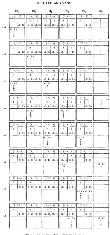
( 2 , 3 , 4 ) ( 3 , 4 , 1 ) <21~"> <374> <314> <411-~ ( 3, 2, 1) <2, 1> FIG. lO--ContinuedN o w , let us consider a simple example as shown in Fig. 10. There are five wedges in the systolic array. Initially, the label of the wedge in PEg is i and the sequence number of each wedge is 1. Since (1, 2, 3) and (3, 2, 1) are the first wedges of regions, their back edges are set to null in Step 2.
When Step 3 is completed, the wedges have the same label if and only if they are in the same region. And, each wi, j for i = 1 to m and j = 1 to [R i I, have sequence number j. Then we can apply a sorting process on the set of wedges wl, w 2 . . . . , w2,
242 SHIH, LEE, AND YANG in the systolic array according to the following n~es:
(7a) w i < wj, if LABEL(wi) < LABEL(wj). (7b) w~ < wj, if LABEL(wi) = LABEL(wj) and
SEQNO(w~) < SEQNO(wg). (7c) w~ > wj, otherwise.
The above sorting process is the main task of Step 4. We can use the odd-even transposition sort [Baud 78, Knut 72] and zero-time sorter to accomplish the sorting process. When the sorting process completed, the wedges in the systolic array are in the following sequence: wx,1, Wl,2, . . . , Wl, IRxl , W2,1, W2,2, . . . , W2,1R21 , . . . , Wrn,1 , Wrn,2 , . . . , Wm, iRml , where wi, i and wi, j+ 1 are contiguous, for i = 1 to m and j = 1 to IR~I and Wi, ig,i and wi, 1 are also continuous, for i = 1 to m.
Since there are 2n wedges output from phase one, the phase two algorithm needs
O ( n ) processing elements. In O ( n ) time steps all of the directed edges can be fed into the systolic array, move forward and backward, and, finally, leave the systolic array. So, the time complexity of the phase two algorithm is O ( n ) .
6. CONCLUSIONS
In this paper, we showed how a systolic algorithm can be constructed to extract all regions of a planar graph. We believe that the techniques developed in this research can be used to develop a systolic algorithm to solve the polyhedra congruity problem discussed in [Sugi 84]. We are presently working on this research and we hope that we can report progress in the near future.
In the process of demonstrating the practical value of our region extraction algorithm we found another interesting research topic. That is, how are we going to put a label, say a 2-digit integer into a region appropriately. We should put this integer inside the region without touching the sides of the region and it should be close to the center as much as possible. We are also working on this research topic.
REFERENCES
[Baud 78] G. Baudet and D. Stevenson, Optimal sorting algorithms for parallel computers, IEEE Trans. Comput. C-27, No. 1, 1978, 84-87.
[Knut 72] D. E. Knuth, The Art of Computer Programming, Vol. 3, Addison-Wesley, Reading, MA, 1972. [Lee 81] D. T. Lee, H. Chang, and C. K. Wong, An on-chip compare/steer bubble sorter, IEEE Trans.
Comput. C-30, No. 6, 1981, 396-405.
[Mira 83] G. Miranker, L. Tang, and C. K. Wong, A zero-time VLSI sorter, I B M J. Res. Develop. 27,
No. 2, 1983, 140-148.
[Niev 82] J. Nievergelt and F. P. Preparata, Plane-sweep algorithms for intersecting geometric figures,
Commun. A C M 25, No. 10, 1982, 739-747.
[Sham 78] M. I. Shamos, Computational Geometry, Ph.D. dissertation, Computer Science Department, Yale Univ., New Haven, CT, 1978.
iSugi 84] K. Sugihara, An n log n algorithm for determining the congruity of polyhedra, J. Comput. System Sci. 29, No. 1, 1984, 36-49.