國
立
交
通
大
學
電機學院 電信學程
碩
士
論
文
低旁波瓣之洩漏波天線陣列設計
Design of Low Side Lobe Level Leaky Wave Antenna Array
研 究 生:邱文斗
指導教授:周復芳 博士
低旁波瓣之洩漏波天線陣列設計
Design of Low Side Lobe Level Leaky Wave Antenna Array
研 究 生:邱文斗
Student:Wen-Tou Chiu
指導教授:周復芳 博士
Advisor:Christina F. Jou
國 立 交 通 大 學
電機學院 電信學程
碩 士 論 文
A ThesisSubmitted to College of Electrical and Computer Engineering National Chiao Tung University
in partial Fulfillment of the Requirements for the Degree of
Master of Science in
Communication Engineering Feb. 2010
Hsinchu, Taiwan, Republic of China
低旁波瓣之洩漏波天線設計
學生:邱文斗
指導教授
:周復芳 博士
國立交通大學 電機學院 電信學程碩士班
中文摘要
本篇論文提出一種降低旁波瓣的微帶線洩漏波天線之設計,由於傳統微帶線洩漏波天線末 端開路的架構,使得行進波在微帶線末端,因不連續而造成反射,此反射能量將沿著相反方向 傳遞能量,同時也將此反射能量向外輻射,形成了不想要的旁波瓣。 此架構主要包含三個短洩漏波天線所組成的陣列天線,將反射波能量以再利用的方式,將 輻射後剩餘的能量導引,並分別饋入其餘的兩個陣列天線中,將反射波功率再輻射利用,本天 線是製作在 FR-4 板材上,操作頻率為 4.4GHz,在場型的量測中,波束方向為~30,3dB 波束 寬度為~40,天線增益為+8.5dBi,旁波瓣位準為 -13dB。 利用此設計有效降低旁波瓣位準及波束寬度,對實際應用有助於降低干擾,同時陣列天線 的結構也提高天線的方向性,應用在車輛防撞系統中可以提升系統的訊雜比。Design of Low Side Lobe Level Leaky Wave Antenna
Array
Student:
Wen-Tou ChiuAdvisors:
Dr. Christina F. JouDegree Program of Electrical and Computer Engineering
National Chiao Tung University
ABSTRACT
In this paper, We propose a compact leaky-wave Antenna array to reduce side lobe level. Since the travelling wave propagating on the antenna will leak out the energy to the free space. But due to the discontinuity at the end of the antenna that will cause the reflected wave and propagate opposite direction. Then radiate unwanted side lobe. We reuse the reflected power due to the reflected power from the end of the microstrip line can reduce the side lobe level.
The antenna array consist of 3 elements, each one has 1 long. We guided the remained reflected power and split the power equally with the same phase difference into 2 paths then inject into each antenna elements. This antenna is fabricated on FR-4 PCB and operating at 4.4GHz. And the measurement results shows gain +8.5dBi, main beam angle is about 30, beam width is about 40 and side lobe level is -13dB.
This design can reduce side lobe level effectively which may reduce the interference and utilize the array structure to improve the directivity. It is suitable for vehicles avoidance collision system, point-to-point radio communication and millimeter-wave applications.
致
謝
首先要感謝我的指導教授周復芳老師,在這段期間給我的指導,使我得而順利完成碩士研 究,同時要特別感謝口試委員吳霖堃及高曜煌教授對論文所提出的建議與指正,使我在論文研 究上獲益良多。 接著要感謝 919 實驗室的各位學長、同學及學弟妹們,因為有你們,在這實驗室裡總是充 滿著歡笑,感謝各位在我求學路上,和我一起相互砥礪;此外,也要感謝天線量測實驗室的同 學,協助架設天線量測的環境,使得天線場形的量測得以順利的完成,同時也從中學習到很多 寶貴的經驗。 最後,要感謝我的太太佩玲,在這一段漫長的時間裡,默默地支持我完成學業,讓我能無 後顧之憂,專心於研究之上,以及我那貼心的女兒芳琪、芳愉及多多,帶給我很多的歡樂。還 有許多曾經幫助過我的人,在這裡我要表達我對你們的謝意。僅以此小小成果獻給我的家人, 並與你們分享我的喜悅。 邱文斗 於 風城交大 2010.02Table of contents
Page C H I N E S E A B S T R A C T … … … . . . i A B S T R A C T … … … . . … … … . i i A C K N O W L E D G M E N T S … … … i i i T A B L E S O F C O N T E N T S … … … . . . … … … i v L I S T O F T A B L E S … … … v L I S T O F F I G U R E S … … … . . . . v i Chapter 1 Introduction 1.1 Motivation………..………..………..1 1.2 Literature survey….………..………….…………..………..2 1.3 Chapter organization………...………...4Chapter 2 Theory of Leaky-Wave Antenna 2.1 The basic operating concept...……….………...5
2.2 Propagation phenomenon on MLWA………….……… …………...………….……..8
2.3 Discussion on leaky mode.…...………...12
2.4 Dispersion characteristic of MLWA ………...13
2.5 Frequency scanning capability of MLWA………...15
2.6 Design of MLWA.………...………16
Chapter 3 Low Side Low Level LWA Design 3.1 Design of low side lobe LWA….……….………….…… ………...19
3.2 Array theory………..………..… ………20
3.3 The Antenna structure..………..… ……….21
3.4 Simulation and Measurement Results...………..… ………24
3.5 Conclusion………..… ………31
Chapter 4 Future Study 4.1 Future Study……….35
LIST OF TABLES
TABLE 1.1 Comparison between different methods.………...………3 TABLE 3.1 Dimension of the proposed antenna structure………...………….………...23
LIST OF FIGURES
Fig. 1.1 The aperture-coupled and patch antenna design………...……….2
Fig. 1.2 The aperture-coupled and patch antenna array...……….………..3
Fig. 2.1 The surface wave and space wave of the LWA……….……….………...9
Fig. 2.2 Field distribution of microstrip line (E-field = solid, H-field = dashed)……….13
Fig. 2.3 Dispersion diagram of the LWA……….………..………...14
Fig. 2.4 Normalized propagation constant…...………..………...14
Fig. 2.5 Coordinates of the microstrip leaky wave antenna…..………..………..16
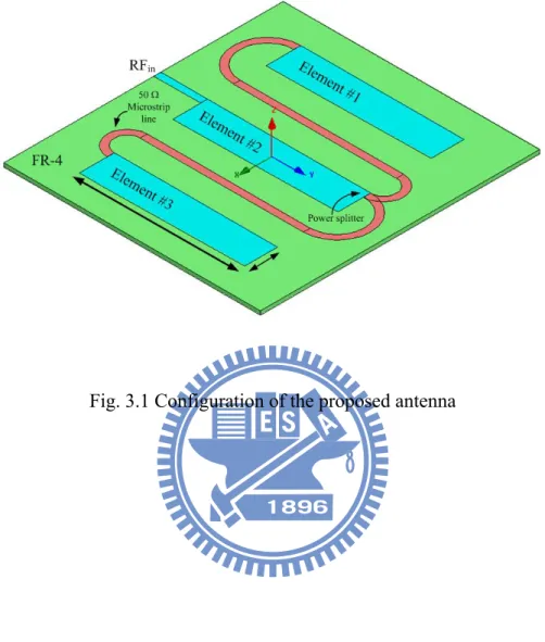
Fig. 3.1 Configuration of the proposed antenna.………...22
Fig. 3.2 Antenna structure and dimension……..………..………...23
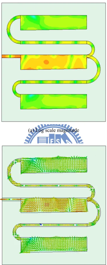
Fig. 3.3 The current distribution of the LWA....………..………...25
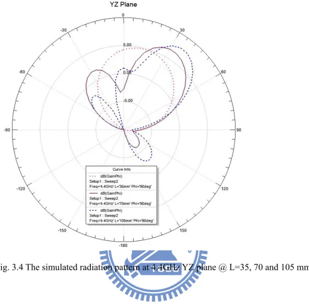
Fig. 3.4 The simulated radiation pattern at 4.4GHz YZ plane @ L=35, 70 and 105 mm ...…….…26
Fig. 3.5 The simulated radiation pattern at 4.4GHz XY plane @ L=35, 70 and 105 mm…………27
Fig. 3.6 The simulated radiation pattern at 4.3, 4.4 and 4.5 GHz YZ plane ...…………...28
Fig. 3.7 The simulated radiation pattern at 4.4 and 4.5 GHz XZ plane…... ...…………...29
Fig. 3.8 The radiation efficiency………...…... ...…………...29
Fig. 3.9 The simulated radiation pattern at 4.4GHz.…..……..………...30
Fig. 3.10 Simulated 3D radiation pattern at 4.4 GHz …..……..………...31
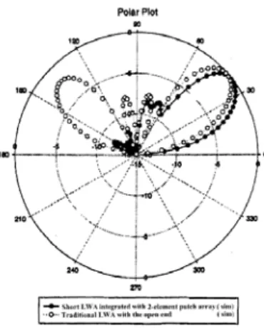
Fig. 3.11 Simulated and Measured radiation pattern of the LWA………..32
Fig. 3.12 Simulated and Measured return loss of the proposed LWA…..………..33
Fig. 3.13 Antenna pattern measurement environment………..………..33
Chapter 1
Introduction
1.1 Motivation
Recently, there is much interest in vehicle collision avoidance system to enhance the traffic safety issues. Conventional Microstrip Leaky-Wave Antenna (MLWA) has many advantages for these applications such as low profile, less weight, easy to fabrication, simple impedance matching and beam scanning features. In 1979, Menzel first constructed the LWA on the microstrip line [1]. Compared to resonant antennas, the MLWA has the wider bandwidth due to the traveling wave characteristic. The advanced researches on its nature of the leaky from higher order mode are describes by Oliner [2]. Subsequently, Oliner and Lee clarified the confusion of properties and divided the leakage modes into forms the surface wave and the space wave. And the radiation characteristic is distributed by the space wave.
One important feature of the MLWA is that the capability of frequency scanning operation. The radiation pattern of narrow beam of MLWA can sweep an angle region by changing frequency. Based on this capability, the MLWA is very suitable for antenna scanning systems. But in practical, there is a serious problem about the long length of the MLWA. Usually, the MLWA needs more than five wavelengths to radiate efficiently, or a reflected wave at open structure end would propagate backwardly in the microstrip line. A large back lobe would be produced by this reflected wave. Hence, there has been a lot of research devoted to study this issue with the hope to reduce the MLWA length without the reflected wave.
The microwave leaky-wave antenna integrated here also cause the main beam narrow as a pencil beam and scanning in the elevation direction. Due to the beam
steering capability, the active aperture-coupled leaky-wave antenna could be used in Global Positioning System (GPS). The GPS can aid to fix position in air traffic control, collision avoidance system, or radiolocation, etc. Thus, it will have a great potential in the future.
1.2 Literature survey
There are so many methods to reduce the side lobe level in MLWA design. Conventionally, place a resistive terminated load at the end of the LWA to absorb the reflected power, but the will get poor radiation efficiency due to waste remained power. The aperture-couple structure has first proposed by Pozar in 1985, and is used to feed microstrip patch antenna. This structure provides an excellent shielding to eliminate the interference of the circuit and reduce the whole circuit size. And also the reflected power is radiate to other directions. The last method is to add some directive elements at the end of the LWA to reduce the side lobe. Below is a comparison of those methods.
Fig. 1.2 The aperture-coupled and patch antenna array [4]
Methods Pros Cons
Increase the length of the antenna
Good radiation efficiency Encounter size issue
Terminated[1] Easy and simple Poor radiation efficiency Backside
aperture-coupled[3]
May reduce SLL Extra side lobe under the ground plane
Add directive elements[4] Reduce SLL effectively Gain as the same as origin Combined with array (this
work)
Not only reduce the SLL but also increase the gain
Larger the area
1.3 Chapter Organization
This thesis is organized as follows. In chapter 1, include motivation and introduction at beginning. In chapter 2, we will present the basic theory of LWA structure. And before that, we will review some basic theories such as, travelling wave, leaky mode, and frequency scanning mechanisms. In chapter 3, we will show the design methodology of a novel structure for the reduce side lobe level. And then, we will show the experimental results of this design. in chapter 4, the results and discussion antenna has been presented. The last, chapter 5, we will give the summary and the conclusion and the future study.
Chapter 2
Theory of Leaky-Wave Antenna
In this chapter, we will demonstrate the leaky phenomenon on the microstrip line, the radiation characteristics of the microstrip leaky wave antenna and design consideration. Based on the features of the microstrip leaky wave antenna, it is an effective technique for providing the direction steering of the transmit/receive modules. And the frequency beam-scanning microstrip line leaky wave antenna has become more popular for extensive research.
A major problem of leaky-wave antenna is the long length of the structure. The length of leaky-wave antenna acquires ten times wavelengths to radiate efficiently. Otherwise, the open ended leaky-wave antenna results in large reflection power of microwave signals. As a result, the reflection power would cause undesired interference in communication systems.
2.1 The Basic Operating Concept
There are several wave modes propagate in microstrip line on substrate. A surface wave and space wave are two forms of leakage. One of the higher order modes that usually used are the first higher mode (EH1, leaky mode) become leakage at the lower
frequency than dominant mode to obtain a radiation characteristics. A simple traveling wave antenna as the microstrip line leaky wave antenna was investigated in [1]. The leaky phenomenon was detected subsequently by Oliner and Lee [2]; the traveling wave in a microstrip leaky wave antenna would leak power to air due to a small attenuation constant. Comparing to resonator antenna operated in fundamental mode, the microstrip leaky antenna has a larger bandwidth due to the traveling wave
in the microstrip line. This leaky mode antenna also possess the advantages of having a low profile, less weight, simple construction, being simple to fabricate and ease of matching. In addition, narrow beam width and frequency scanning characteristics are the extraordinary properties of the microstrip leaky wave antenna’s physical behavior. Recently, this microstrip leaky wave antenna has attracted a lot of interests to investigate.
A leaky-wave antenna is basically a waveguiding structure that processes a mechanism the permits it to leaky power all along its length. Because of the leakage, the leaky waveguide has a complex propagation wave number, with a phase constant and a leakage constant ; is large or small depending on whether the leakage per unit length is large or small. A large implies that the large leakage rate produces a short effective aperture, so that the radiated beam has a large beamwidth. Conversely, a low value of results in a long effective aperture and a narrow beam, provided the physical aperture is sufficiently long.
A typical leaky-wave antenna might be about 20 wavelengths long, so that the beamwidth of the radiation would be about 4 or so if the beam direction is about 45 from the leaky waveguide axis. A short length LWA may encounter with a larger side lobe level.
Because the phase constant changes with frequency, the beam direction also changes with frequency, and the leaky-wave antenna can be scanned by varying the frequency. The precise ways in which changes in frequency affect the various properties of leaky-wave antenna are considered in detail later.
Since power is radiated continuously along the length, the aperture field of a leaky-wave antenna with strictly uniform geometry has an exponential decay, so that the sidelobe behavior is poor. The practice is then to vary the value of slowly along the length in a specified way while maintaining constant, so as to adjust the
amplitude of the aperture distribution to yield the desired sidelobe performance. This tapering procedure is well known.
An individual leaky-wave antenna is clearly a line-source antenna; the design produces the desired beam behavior (usually a narrow beam) in the scan plane, but the radiation pattern in the cross-plane is just a fan beam whose detailed beam shape depends on the cross-sectional dimension of the leaky-wave antenna, Techniques are available for narrowing the beam in the cross-plane, such as the use of a horn or placing the line-source antenna in an array.
There are two different basic types of leaky-wave antennas, depending on whether the geometry of the guiding structure is uniform or is periodically modulated along its length. These two types are actually similar in principle to each other, but their performance properties differ in several ways and they face somewhat different problem in their design. All leaky-wave line-sources of the uniform type radiate into the forward quadrant and can scan in principle from broadside to end fire, with the beam nearer to end fire at the higher frequencies. In practice, however, one cannot get too close to end fire or to broadside. But how near those limits can be approached depends on the specific structure. For example, suppose the cross section of the guiding structure contains dielectric material in part and air in part, and has a slow-wave range( > k0) and a fast-wave range( < k0), where k0 is the free space
wave number in air. Then, the transition between the two ranges is usually a rapid one, occurring at end fire (when = k0), and the beam can be scanned very close to end
fire. In the second type of leaky-wave antenna, the periodic type, some periodic modulation of the guiding structure is introduced, and it is this periodicity that produces the leakage. The periodic modulation itself is uniform along the structure’s length, again except for the small taper of periodic properties along the length to control the sidelobes. An important difference between uniform and periodic
leaky-wave antennas is that the dominant mode on the former is a fast wave that therefore radiated whenever the structure is open. On the other hand, the dominant mode on the periodic leaky-wave antenna is a slow wave that does not radiate even though the structure is open.
Surface-wave antennas, leaky-wave, and slot arrays are all members of the family of travelling-wave antenna. They are similar to each other in some evident respects, but they all differ from each other in important ways that lead to different design procedures and to different performance expectations. Surface-wave antenna are purely end-fire antennas, whereas leaky-wave antennas and slot arrays do not radiate well in the end-fire direction and, in fact, are designed either to radiate in some other direction or to scan a range of angles. The basic guiding structure for surface-wave antenna is an open waveguide whose dominant mode is purely bound, so that the surface wave will radiate only at discontinuities, such as the very end of the waveguide. It does not radiate along the length of the guide because the surface wave is slow wave, whereas a uniform leaky-wave antenna, which supports a fast wave, leaks power all along the length of the waveguide.
A major problem of microstrip leaky wave antenna is the long length of the structure. We design the feeding network by using the asymmetric feeding structure. For the LWA design, there are two major current paths to radiate.
At this work, the simulator is based 3-D full-wave EM solver (Ansoft HFSS). Later, we will show the simulation result of this design.
2.2 Propagation phenomenon on MLWA
In the microstrip line, there exist several modes while electromagnetic waves travel in the line. Uniform is operated in the fundament mode to transmit power. To perform a leaky wave we employ a high order mode in an appropriate region of
operation frequency.
The dominant mode traveling in a uniform microstrip line is a slow wave relative to traveling in free space. As a result, the dominant mode cannot be employed to a uniform leaky-wave antenna. To perform a uniform leaky-wave antenna, we employ a high order mode in an appropriate range of operation frequency. Among the higher modes, the first higher mode is the most practical mode to excite. Compare to the dominant mode, the higher mode has a nonzero cutoff frequency. The cutoff frequency of the antenna is determined by the guided width. The leakage wave can be distinguished into two forms surface wave and space wave. Fig. 2.1 shows the top view of the strip line.
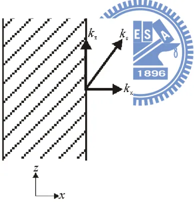
Fig. 2.1 The surface wave and space wave
2 2 2 z s x k k k (2-0) j kz
For actual leakage, the kx must be real so that ks.
leaky waveguide, and the determination of and , whether theoretically or experimentally, is in most cases the most difficult part of the design. Their knowledge, however, is essential to any systematic design procedure.
Once and are known as a function of frequency and cross-sectional geometry, the principal behavioral features of a leaky-wave antenna follow very quickly. Such features include the beam direction, the beamwidth, the radiation efficiency, the variation of the scan angle with frequency, and the taper in of required to control the sidelobes.
The major behavioral features follow directly once the values of and are known, and they are given to a good approximation by a set of very simple relations. We first consider the beam direction and the beamwidth:
ko m sin (2-1) m o L cos ) / ( 1 (2-2)
Where m is the angle of the maximum of the beam, measured from the
broadside direction, L is the length of the LWA, is the beamwidth, and the k0 is the
free-space wave number (=2/0), Both m and are in radians in Eqs. (2-1) and
(2-2). The beamwidth is determined primarily by antenna length L, but it is also influenced by aperture field amplitude distribution. It is narrowest for a constant aperture field and wider for sharply peaked distributions. For a constant aperture distribution, the unity factor in the numerator should be replaced by 0.88; for a leaky-wave structure that is maintained uniform along its length, consistent with 90 percent radiation, the factor should be 0.91; for tapered distribution that is sharply peaked, the factor could be 1.25 or more.
The antenna length L is usually selected, for a given value of , so that 90 percent of the power is radiated, with the remaining 10 percent or so absorbed by a
matched load. Attempting to radiate more than 90 percent or so creates two problems; First, the antenna must be made longer, and second, the variation in (z) required to control the sidelobes becomes extreme. For 90 percent of power radiated, we find
ko L / 18 . 0 (2-3)
This simple but useful relation follows from writing )] / )( / ( 4 exp[ ) 0 ( ) ( o L ko P L P (2-4)
where P(L) is the power remaining in the leaky mode at z=L and P(0) is the power input at z=0. In both L and are specified independently, the percentage of power radiated can deviate significantly from the desired 90 percent. In fact, the is a function of frequency, so that the radiation efficiency will change somewhat as the beam is frequency scanned. The 90 percent figure is usually applied to the middle of the scan range.
The radiation pattern can be found by taking the Fourier transform of the aperture distribution. When the geometry of the leaky-wave antenna is maintained constant along the antenna length, the aperture field distribution consists of a traveling wave with a constants and , meaning that the amplitude distribution is exponentially decaying. If the antenna length is infinite, one finds that the pattern R() is given by 2 2 2 ) sin / ( ) / ( cos ) ( ko ko R (2-5)
Which does not exhibit any sidelobes. If the antenna length is finite, the expression for R() becomes more involved, and the pattern possesses sidelobes that modify the basic shape for infinite length.
Where is the angle of the maximum of the beam, measured from the broadside direction, L is the length of the LWA, is the beamwidth, and the k0 is the free-space wave number (=2/0), Both m and are in radians in Eqs. (2.1) and
(2.2) the wavelength of the operating frequency of the antenna.
2.3 Discussion on Leaky mode
Microstrip guided-wave structure usually operated in the fundamental mode (EH0) which is quasi-TEM mode which does not radiate. The electric and magnetic
fields of such bound mode are shown in Fig. 2.2 it is even symmetry about the axial centerline.; However, if the fundamental mode is blocked (or suppressed), the 1st higher order mode can radiate and thus, the microstrip line can utilized as leaky traveling wave antenna. But the 1st higher order mode is one such radiating mode, and exhibit odd symmetry about the axial centerline the fields. This is due to phase reversal in the center at the center of the structure allowing the fields to decouple into the substrate and free space regions. The leaky wave region begins when = (cut-off frequency) and continues as long as < k0. The width of the antenna was
increased, the cutoff frequency of the leaky region decreased. As the permittivity of the substrate was decreased, the cutoff frequency of the leaky region increased, as did the bandwidth of the leaky region.
The lowest mode on microstrip line is always purely bound mode. Then the higher order modes will leak the power away when the frequency is lowered below some critical value. When the open microstrip line is operated in first higher order mode, the electric field are roughly sketched in Fig. 2.2. From the horizontal electric field polarization configuration on the top of the strip, it is obvious the radiation will occur above the strip for the first higher mode. The leakage power is in the form of surface wave. As in microstrip patch antenna, the structure can be used to be a practical antenna. In the next section, we will extract the main factors of the radiation characteristic by utilizing and of the leaky mode.
Fig. 2.2 Field distribution of microstrip line (E-field = solid, H-field = dashed) [5]
2.4 Dispersion characteristic of LWA
The surface wave number can be expressed in the form of -j, where is phase constant and is attenuation constant. We employed the rigorous (Wiener-Hopf) solution mentioned in [5] to obtain the normalized complex propagation constant. Fig 2.3 shows the variation of the normalized phase constant (/k0) and normalized
attenuation constant (/k0).
> ks, = 0 (Region I) bound mode region;
ks > > k0, small (Region II) surface wave leakage region;
k0 > , small (Region III) surface wave and space wave leakage region;
Fig. 2.3 Dispersion diagram [5]
2.5 Frequency scanning capability of LWA
Let us check the Eq. (2-1), /k0=1 corresponds to end fire, and /k0=0
corresponds to broadside. The /k0 variation near to cutoff(near to broadside) is seen
to be much the same whatever the filling factor of the guiding structure. The big difference occurs near the end fire. The variation with frequency for the air-filled case in seen to be quite slow near the /k0=1 line because the curve asymptotically
approaches that line as the frequency becomes large. Several significant steps in design of the microstrip leaky wave antenna depends on the plot of and versus frequency. The procedures are summarized below and are only valid in leakage condition.
1) At the onset of the space wave (= k0, corresponding to f ~ GHz in Figure 2.4), the
main beam direction is theoretically parallel to the end-fire direction and the beam moves to the broadside direction as the frequency decreases.
2) As the frequency decreases, due to a small α, a large amount of power is reflected from the open structure end of the microstrip line, in turn producing a large back lobe at the same angle opposite to the broadside direction. A longer length of the antenna can reduce the back radiation.
3) In the radiation region, corresponding to reasonable value (roughly contained between 4.2 GHz and 5.0 GHz in Figure 2.4), a continuous leaky wave occurs along the microstrip line. As a result, a large radiation space wave and a small amount of reflected wave are obtained. The beamwidth of the leaky wave is very narrow.
4) As the frequency continues to decreases, the attenuation constant of the guided mode.
Fig. 2.5 Coordinates of the microstrip leaky wave antenna [5]
2.6 Design of LWA
According to the theory of section 2.2, we can determine the complex propagation constant as plotted in Figure 2.4 by changing the width of the microstrip leaky wave antenna.
The leaky mode region is began from /k0 = /k0 and ended at /k0 > 1. Here,
the width of MLWA is designed to be 15mm. Consequently, the leaky mode region is between about 4.2GHz to 5.0 GHz. This leaky region is calculated based on the assumption that the infinite length of the microstrip line.
In practical, the antenna length is always not infinite. A conventional MLWA with finite length usually has an open structure end. A finite length of microstrip line would cause large reflection wave due to the mismatch of the open structure end. The reflection wave also leaks power to air and produces a large back lobe. The MLWA proposed by Menzel was mentioned in [3] that the short length (2.23λ0) of the
reflected from the open structure end, and produces a large back lobe. To radiate 90% of the power, the length would be increasing to 4.85λ0.
Usually, the length of the MLWA requires about five wavelengths to suppress back lobes and radiate out power efficiently. A rule that considers the remnant guided wave power is applies to design the length of the microstrip leaky wave antenna. The remnant guided wave power (e-2a L) must be less than 5% when the length L of the antenna is chosen. That is, e-2a L < 0.05. A rigorous (Wiener-Hopf) solution [12] is employed to find the normalized complex propagation constant /k0 - j/k0 of the first
higher mode, where /k0 is the normalized phase constant and /k0 is the normalize
attenuation constant. As the normalized phase constant /k0 is less than 1, the leakage
occurs in the form of space wave.
In order to greatly reduce the sidelobe level and to control the pattern in other ways, it is customary to appropriately taper the amplitude of the aperture distribution. The procedure to design the leaky-wave antenna so that it produces a final desired radiation pattern is straightforward, though somewhat complicated. First, the final desired radiation pattern is specified, and then the corresponding aperture amplitude distribution is determined by standard antenna techniques. Next, by using the expression derived below, the value of /k0 are computed as a function of position
along the antenna length in accordance with aperture amplitude distribution. At the same time /k0 must be maintained constant along the length so the radiation from all
parts of the aperture point in the same direction. Finally, from the theory that relates and to the geometry of the structure, we compute the tapered geometry as a function of position along the antenna length.
However, since must not be changed, the geometry must be further altered to restore the value of , thereby changing somewhat as well. In practice, the difficulty requires a two-step process for most leaky-wave antennas, which is not bad. Because
of this added complexity, one seeks leaky-wave structures for which on can vary geometric parameters that change and essentially independently.
Chapter 3
Low Side Lobe Level LWA Design
In recent years, there several configurations which can provide the low side lobe level design. However, traditional LWA is large in size and is not suitable for a radar system. In addition, the large side lobe level may interfere the other circuits or communication systems. Therefore, it is very necessary to develop a new structure which is suitable for nowadays applications.
In this chapter, we demonstrated a new configuration of the low side lobe LWA based on the leaky-wave antenna structure which has better gain characteristics that will improve the system performance. The proposed structure is composed of the conventional open end leaky-wave antenna with adding array structure to reducing the side lobe. According to the measured results, the impedance bandwidth is about 4.4GHz. The antenna peak gain we obtained is about 8.5dBi. Furthermore, the side lobe level of this design is better than 13dB.
3.1 Design of the Low Side Lobe LWA
According to the mentioned above, we know that the main design idea is to reuse the remained reflected power and spitted the power equally and the same phase difference to other elements. In the array theory, there are many factors will affect the radiation pattern, like the distance between the each element or the excided power of each element. That is to say, we can change these factors to design a high gain antenna.
This research adopts an asymmetrical feed line to excite the proposed antenna which is similar to traditional leaky-wave antenna.
The antenna consists of three parts which are the three radiators as an array, power splitter, and transmission lines.
3.2 The array theory
Arrays are found in many geometrical configurations. The most elementary is that of a linear array in which the array element centers lie along a straight line. The basic array antenna model consists of two parts, the pattern of one of the elements by itself, the element pattern, and the pattern of the array with the actual elements replaced by isotropic point sources, the array factor. The total pattern of the array is then the product of the element pattern and array factor. An isotropic radiator is a hypothetical, lossless antenna occupying a point in space and when transmitting radiates uniformly in all directions. It is sometimes referred to as a point source. The radiation fields of an isotropic radiator at the origin of a spherical coordinate system are proportional to r e I r j 4 0 (3-1)
where I0 is the current of point source. The array factor for the array is then the
sum of isotropic radiator antenna response weighted by the amplitude and phase shift introduced in the transmission path connected to each element. The array factor of the array is 0 1 2 2 1 0e j I e j I e j I AF (3-2)
where 0, 1,… are the phases of an incoming plane wave at the element
locations designated 0,1,… For convenience, these phases are usually relative to the coordinate origin. The expression in (3-2) is very general and can be applied to any geometry.
spaced, the array factor expression (3-2) can be simplified. The angle is that of an incoming plane wave relative to the axis of the receiving array. The incoming waves at element 1 arrive before those at the origin since the distance is shorter by an amount dcos . The corresponding phase lead of waves at element 1 relative to those at 0 is dcos . This process continues and (3-2) becomes
1 0 cos cos 2 2 cos 1 0 ... N n nd j n d j d j I e I e e I I AF (3-3)3.3 The antenna structure
Figure 3.1 shows the structure of the proposed antenna which has three parts: a) conventional open end leaky-wave antenna structure, b) adding the power splitter which is connected to the end of the LWA and c) adding the two transmission lines which connect to the other antennas. These configurations are fabricated on the substrate, or FR-4, with a dielectric constant of εr = 4.4 and substrate thickness of h =
1.6mm.
We add the power splitter in order to get remainding reflected power and divided into two parts to improve the antenna gain and the efficiency. The transmission lines should be equal electrically length and minimize the phase difference. The slight of the tapered structure in the LWA is to improve the impedance matching.
The proposed antenna is printed on an FR4 substrate of the dielectric constant of 4.4, the conductor loss (tanδ) of 0.02, and the thickness of 1.6 mm. The structure of the antenna is shown in Fig. 3.1.
Detailed dimensions are listed in Table 3.1. Figure 3.2 shows the structure of the convention open end leaky-wave antenna of which the length L is 70 mm, the width
W is 15mm and the ground plane on the back side of the substrate is 110 mm × 120
The antenna structure and dimensional parameters values are as follows:
Fig. 3.2 Top view of LWA L 110 mm W 120 mm Lleaky 70 mm W1 15 mm W2 14 mm S 40 mm Wstrip 3 mm h 1.6 mm r 4.4 ---
3.4 Simulation and Measurement Results
In our study, for the original configuration which is similar to the conventional open end leaky wave antenna but the ground plane is reduced, we can see the current distribution which demonstrates that most of the current distributes at the bottom side of the antenna body and the current flows along the x-axis. Meanwhile, the length of antenna body is about a wavelength for the operating frequencies so the wave will travel on antenna body but there still has slight current which distributes on the center of the antenna body. Based on the current distribution mentioned above, the radiation pattern of this configuration will be near to the end-fire pattern in yz-plane. We first proposed the solution which is adding short-circuited stubs to couple the current and the fields to achieve our purpose. To improve the impedance bandwidth, we make a slightly taper on LWA.
The current distribution of the antenna is shown in Fig. 3.3 for operating at 4.4GHz. And the 3D radiation pattern is shown in Fig. 3.4.
(a) Log scale magnitude
(b) Log scale vector field
Fig. 3.5 The simulated radiation pattern at 4.4GHz XY plane @ L=35, 70 and 105 mm
Fig. 3.7 The simulated radiation pattern at 4.4 and 4.5 GHz XZ plane
Fig. 3.9 The simulated radiation pattern at 4.4GHz
(b)
(c)
Fig. 3.10 Simulated 3D radiation pattern at 4.4 GHz (a) Top view (b) Side view (c) Angle view
3.5 Conclusion
Here, a low side lobe level antenna array is designed and tested. This structure provides good impedance bandwidth which is better than the conventional symmetric position antenna. Meanwhile, it shows good radiation characteristics and can provide the average value of the antenna gain about 8.5 dBi. In the operating band, the side
lobe level exceeds the level of 13 dB which achieves the purpose that is improving the unidirectional radiation pattern.
The return loss is computed using Ansoft HFSS and measured using an 8720 vector network analyzer and is shown in Fig. 3.14. There are some small discrepancies between the simulated results and the measured results, which may occur due to the effect the SMA connector and fabrication imperfections. Both the simulation and the measurements show that the antenna operates over the range which extends from 3.0 GHz to 6.0 GHz.
The simulated and the measured radiation patterns at the operating band center frequency, or 4.4 GHz, are shown in Fig. 3.11. The antenna has the 3-dB beamwidth that ranges from 14o to 46 o in the YZ-plane. The return loss is shown in Fig. 3.12.
Fig. 3.12 Simulated and measured return loss of the proposed LWA
Chapter 4
Future Study
This proposed antenna structure is suitable for the many applications which require unidirectional radiation pattern such as traffic control, collision avoidance system, radiolocation, etc. and has great potential for applications in the future.
In the Future, there still have some topics we can research. For the multiple element of antenna array to increase the antenna gain, radiation efficiency, and how to design the antenna structure and phase shifter to scanning the beam direction is what we expected such topics are good researches. Another topic is that how to decrease the operating frequency band under the limited size of the PCB.
For the array antenna, how to improve the radiation performance is a good further research. Besides, enlarging the bandwidth, enhancing the antenna gain or increasing the directivity are also worthy to be studied.
Symbols
:propagation constant
:free-space wavelength
:leakage constant
:phase constant
k
0:free-space wave number
:beamwidth
L :antenna length
m :angle of the maximum of the beam
P(L) :power remaining at z=L
R() :radiation pattern
:
REFERENCES
[1] W. Menzel, “A new travelling-wave antenna in microstrip,” Archiv. Electrnik
Ubertrag Tech., pp. 137-140, Apr. 1979.
[2] A. A. Oliner and K. S. Lee, “The nature of the leakage from higher modes on microstrip line,” in Int. Microwave Symp. Digest, MTT-S, vol.86, no. 1, pp. 57-60, June 1986.
[3] Chien-Jen Wang, Hua-Lin Guan, and Christina F. Jou, “A Novel Method for Short Leaky-Wave Antennas to Suppress the Reflected Wave,” Microwave and
Optical Technology Letters, vol. 36, No. 2, January 2003.
[4] I-Yu Chen, Chien-Jen Wang, Hua-Lin Guan, and Christina F. Jou, “Studies of Suppression of the Reflected Wave and Beam-Scanning Features of the Antenna Arrays,” IEEE Trans. Antennas and Propagation, vol. 53, July 2005.
[5] A. A. Oliner and K. S. Lee, “Microstrip leaky wave strip antennas,” IEEE AP-S
Int. Symp. Dig., Philadelphia, PA, June 1986, pp. 443–446
[6] Y. Li, Q. Xue, E. K.-N. Yung and Y. Long, “A Fixed-Frequency Beam-Scanning Microstrip Leaky Wave Antenna Array,” IEEE Antennas and Wireless Propag.
Lett., vol. 6, pp. 616-618, 2007.
[7] Y. Li, Q. Xue, E. K.-N. Yung and Y. Long, “Fixed-Frequency Dual-Beam Scanning Microstrip Leaky Wave Antenna,” IEEE Antennas and Wireless
Propag. Lett., vol. 6, pp. 444-446, 2007.
[8] I. Hertl and M. Strycek, “Tapered slot antenna with reduced backward radiation,” Micow., Radar and Wireless Communications Conf. pp. 1-4, 19-21 May, 2008.
[9] W. L. Stutzman and G. A. Thiele, Antenna Theory and Design, 2nd ed. New York:
John Wiley & Sons, 1998.
[10] C. A. Balanis, Antenna Theory Analysis and Design, 3rd ed. New York: John
Wiley & Sons, 2005.
[11] J. D. Kraus, Antennas for all applications, 3rd ed. New York: McGraw-Hill,
2002.
[12] Ansoft High Frequency Structure Simulator (HFSS) Based on the Finite Element Method.
![Fig. 1.1 The aperture-coupled and patch antenna [3]](https://thumb-ap.123doks.com/thumbv2/9libinfo/8141343.166681/10.892.141.757.493.1016/fig-the-aperture-coupled-and-patch-antenna.webp)
![Fig. 2.2 Field distribution of microstrip line (E-field = solid, H-field = dashed) [5]](https://thumb-ap.123doks.com/thumbv2/9libinfo/8141343.166681/21.892.185.610.120.275/fig-field-distribution-microstrip-field-solid-field-dashed.webp)
![Fig. 2.3 Dispersion diagram [5]](https://thumb-ap.123doks.com/thumbv2/9libinfo/8141343.166681/22.892.150.731.117.1096/fig-dispersion-diagram.webp)
![Fig. 2.5 Coordinates of the microstrip leaky wave antenna [5]](https://thumb-ap.123doks.com/thumbv2/9libinfo/8141343.166681/24.892.192.711.119.438/fig-coordinates-microstrip-leaky-wave-antenna.webp)