國
立
交
通
大
學
電機與控制工程學系
碩
士
論
文
具有可變係數之
AES 加解密器
之矽智產設計與晶片實現
IP-based design and chip implementation of the AES
coprocessor with configurable parameters
研究生:白宗堯
指導教授:吳炳飛 教授
具有可變係數之
AES 加解密器
之矽智產設計與晶片實現
IP-based design and chip implementation of the AES
coprocessor with configurable parameter
研究生:白宗堯 Student:Tsung-Yao Pai
指導教授:吳炳飛 教授 Advisor:Prof. Bing-Fei Wu
國 立 交 通 大 學
電 機 與 控 制 工 程 學 系
碩 士 論 文
A ThesisSubmitted to Department of Electrical and Control Engineering College of Electrical and Computer Engineering
National Chiao Tung University in partial Fulfillment of the Requirements
for the Degree of Master
in
Electrical and Control Engineering July 2006
Hsinchu, Taiwan, Republic of China
具有可變係數之 AES 加解密器
之矽智產設計與晶片實現
學生: 白宗堯 指導教授:吳炳飛 教授
國立交通大學電機與控制工程學系(研究所)碩士班
摘 要
在此篇論文中,我們提出了一個具有可變係數的AES (Configurable AES)加
解密器,使得在不同的m(x)、c(x)和affine transformation 係數選擇之下,可產 生多變的 AES 演算法,藉以進一步的提高系統的安全性。並由於我們所提出之 硬體實現仍能具有高效能的表現,讓此構想可以跟到上網路傳輸速度的進步,運 到用Gigabit 的光纖與乙太網路安全晶片上。在規格上,除了可調變係數之外, 並支援128, 192, 256-bit 三種金鑰長度以及 ECB, CBC 兩種加密模式。對於加解 密過程中所需之金鑰,我們也提出了一種可同步計算金鑰的電路,而不需使用額 外的記憶體來儲存金鑰。此外,為了降低硬體成本和提升效率,我們採取 Composite Field Arithmetic 運算來實現演算法的核心 S-Box 部分,並將架構下的 矩陣乘法運算合而為一以縮短運算時間。最後,以強調重複利用的矽智產方式 (IP-based)實現,並遵守 AMBA AHB Slave 傳輸協定,以助於未來在系統面的開
發。在本論文的成果方面,此Configurable-AES 加解密器以 UMC 0.18μm CMOS
製程實現,擁有約81K 的 gate counts,在最高處理速度下,對於 128/192/256 三
IP-based design and chip implementation of the AES
coprocessor with configurable parameter
Student : Tsung-Yao Pai Advisor : Prof. Bing-Fei Wu
Department of Electrical and Control Engineering
National Chiao Tung University
ABSTRACT
In this paper, we implement a configurable AES (C-AES) coprocessor, which supports all specified key lengths, such as 128, 192, and 256 bits, and both the ECB and CBC operation modes. The round keys for encryption and decryption are generated on the fly without any internal memory. Specifically, it provides the flexibility to change the parameters of each transformations, such as the irreducible polynomial, the affine matrix, the affine constant, and the row vector of the matrix used in MixColumns(). These parameters are online changeable, i.e., they are also the inputs of the circuit. For increasing the speed, an optimized combination is presented in the proposed architecture. By using basis conversion and composite field in
SubBytes(), and pre-calculating the values of every power of xtime() of constants in MixColumns(), the matrix multiplications in SubBytes() and MixColumns() can be
integrated into a new transformation to reduce the computation path. Furthermore, all arithmetic components are also reused for the encryption and the decryption data paths. The proposed design has been implemented using a UMC 0.18μm CMOS technology. The throughput is about 3.2Gbps for 128-bit keys, 2.67Gbps for 192-bit keys, and 2.29Gbps for 256-bit keys, respectively. The total gate count is about 81K. This work provides a customized AES cipher to let users change parameters; therefore, it can be utilized in the applications requiring customized security, .e.g., the virtual private networks (VPN).
致謝
首先,要感謝我的指導教授 吳炳飛博士二年來的教導,感謝您提供豐沛的 研究資源與良好的學習環境,在設備與開發工具可以說是應有盡有,讓我懂得如 何開發設計,以符合市場與業界的需求。另外,也要感謝我的大學專題指導教授 張孟洲博士,是您帶領我進入數位IC 設計的領域,啟蒙我做研究該有的 sense, 您認真謙虛的態度,是我學習的榜樣。 此外,最要感謝的人,就是曾經帶領過我的顏志旭學長,林重甫學長,彭信 元學長,在你們的教導之下,都讓我學到很多不同領域的東西,使的我在各方面, 都有顯著的成長。 當然,也要感謝實驗室的夥伴們,學長晏阡、培恭、俊傑,學姊映伶,同學 元馨、岑偉、小熊、子萱、ppj、皓昱,學弟秉宗、敏偉、晉源,有你們的陪伴, 讓研究和生活都充滿了樂趣。 最後,感謝我親愛的父母及家人,有你們在背後辛苦的付出和支持,今天才 能順利完成研究所學業,這一切都絕不是光靠我一個人能做得到的,謝謝你們。Publication & Award
發表論文 ▓Chih-Hsu Yen, Tsung-Yao Pai, and Bing-Fei Wu, “The Implementations of the Reconfigurable Rijndael Algorithm with Throughput of 4.9Gbps,”
Proceedings of the 16th VLSI Design/CAD Symposium, Aug. 2005.
得獎紀錄 ▓2005, 第七屆矽智產SIP設計競賽 「佳作」 可參數化之高安全度 Rijndael加密演算法
Contents
Chapter 1 Introduction ...1
1.1 Background...1
1.2 Motivation...2
1.3 Organization...3
Chapter 2 AES Algorithm ...4
Chapter 3 Hardware-Reduction Strategy for C-AES ...10
3.1 Previous Work...10
3.2 S-Box Optimization ...11
3.2.1 Composite Field Arithmetic...12
3.2.2 Isomorphism Functions and Basis Transformation...13
3.2.2 Multiplicative Inversion over the Composite Field ...15
3.2.3 The Comparison of Multiplicative Inversion...18
3.3 MixColumns() Optimization ...20
3.4 The Hardware Architecture...21
3.4.1 The Direct Architecture...22
3.4.2 The Combination of SubBytes() and MixColumns()...23
Chapter 4 3-in-1 Key Expansion Design ...28
4.1 The Data Flow Graph of Key Expansion...28
4.1.1 128-bit Key Expansion ...29
4.1.2 192-bit Key Expansion ...29
4.1.2 256-bit Key Expansion ...31
4.2 The Hardware Architecture of 3-in-1 Key Generator ...33
Chapter 5 The Implementation of C-AES coprocessor...37
5.1 Top-level View ...37
5.2 I/O Interface ...39
5.2.1 Input Interface...39
5.2.2 Output Interface ...41
5.3 Parameter initialization Engine...41
Chapter 6 Verification and Result Comparison...43
6.1 IP-Based Design...43
6.1.1 IP Qualification Guideline Overview ...43
6.1.2 Soft IP Design Flow...44
6.2 Chip Design Flow ...46
6.3 Verification Strategy ...48
6.3.1 Untimed functional model ...48
6.3.3 FPGA Prototyping...49
6.3.4 Coding Style Rule Check...51
6.3.5 Code Coverage...51
6.3.6 Design for Testability...52
6.3.7 Physical Verification ...53
6.4 Results and Comparisons...53
Chapter 7 Conclusions and Future Work...57
7.1 Conclusions...57
List of Figures
Fig. 1.1 The concept of cryptosystem...1
Fig. 2.1 Pseudo code of AES encryption. ...4
Fig. 2.2 The encryption procedure of AES algorithm. ...7
Fig. 2.3 Pseudo code of key expansion...8
Fig. 3.1 The outline of the S-Box implementation ...13
Fig. 3.2 The outline of the configurable S-Box implementation...15
Fig. 3.3 The multiplicative inversion based on composite field ((24)2) GF ...17
Fig. 3.4 The implementation of the inversion in (((22)2)2) GF ...18
Fig. 3.5 The operation order of encryption and decryption...22
Fig. 3.6 The direct architecture of parameterized cipher engine in this work. ...23
Fig. 3.7 The combined architecture of the parameterized cipher engine...26
Fig. 4.1 The representations of operation in key expansion. ...29
Fig. 4.2 The 128-bit key expansion for the encryption/decryption. ...29
Fig. 4.3 The 192-bit key expansion for the encryption/decryption. ...30
Fig. 4.4 The rearrangement of the 192-bit key expansion for the encryption. ...30
Fig. 4.5 The rearrangement of the 192-bit key expansion for the decryption. ...31
Fig. 4.6 The 256-bit key expansion for the encryption/decryption. ...31
Fig. 4.7 The rearrangement of 256-bit key expansion for the encryption. ...32
Fig. 4.8 The rearrangement of 256-bit key expansion for the decryption. ...32
Fig. 4.9 The architecture of 3-in-1 key generator module...33
Fig. 4.10 State diagram of the controller for 3-in-1 key generator. ...34
Fig. 4.11 The combination loop in 128-bit key expansion data path...35
Fig. 5.1 Block diagram of the C-AES coprocessor...38
Fig. 5.2 Clock distribution in the different transfer modes...40
Fig. 5.3 Simple block diagram of parameter initialization engine. ...41
Fig. 5.4 The computation schedule of parameter initialization. ...42
Fig. 6.1 Soft IP design flow. ...46
Fig. 6.2 Cell-based design flow ...47
Fig. 6.3 MATLAB software model...49
Fig. 6.4 The C-AES coprocessor on the ARM Integrator...50
Fig. 6.5 The hardware driver running on the ARM ADS. ...50
Fig. 6.6 The report of coding style rule check...51
Fig. 6.7 The report of fault coverage calculated by TetraMax. ...53
Fig. 6.8 The report of code coverage estimated by Verification Navigator. ...52
List of Tables
Table 3.1 Performance analysis of the inversion in section 3.2.3...19
Table 3.2 The critical path of the cipher engine ...27
Table 4.1 The function of data shifting multiplexer in the key expansion ...34
Table 4.2 The input table for the S-Box in key expansion. ...35
Table 4.3 The critical path of the key generator. ...36
Table 4.4 Comparison of 3-in-1 key generator...36
Table 5.1 Pin definition of C-AES coprocessor...38
Table 5.2 The bit number of each changeable coefficient. ...39
Table 5.3 The necessary parameters for the cipher engine and the key generator.42 Table 6.1 Register map of the C-AES coprocessor...51
Table 6.2 The comparison between cipher engine and key generator. ...53
Table 6.3 Area statistics of C-AES coprocessor. ...54
Chapter 1
Introduction
1.1 Background
Due to the growth of applications in Internet and wireless communication, more and more users require the security measures and devices for protecting the data, which users transmit over the channels. Since nobody can guarantee that the information will not be stolen over open communication channels, it is a general way to encrypt the information before they are transmitted into the channels. There are many cryptosystem developed in the past. According to the key type, the cryptosystem can be classified into two type systems, such as the symmetric-key and asymmetric-key cryptosystem. The concept of cryptosystem is illustrated in Fig. 1.1. The plaintext, which will be sent in the transmitter, will be encrypted with the cipher key to generate the ciphertext, and the ciphertext, like a random number, is transmitted in the insecure channel. Finally, the ciphertext will be received in the receiver and be decrypted with the cipher key to recover the plain text.
Fig. 1.1 The concept of cryptosystem.
The symmetric-key cryptosystem, such as DES, AES [1], and 3DES [2], uses an identical key to encrypt the message text and to decrypt the cipher text. The asymmetric-key cryptosystem, such as RSA and Elliptic Curve algorithms [3], uses a different key for encryption and decryption. Different from the asymmetric-key cryptography, the structure of the symmetric-key cryptography is simple. Usually, it consists of a block cipher, and by executing it iteratively, the encrypted data is
generated. The block cipher can be divided into two parts, the nonlinear and linear operations. These operations use the ways of substitution and permutation to cause the diffusion and confusion on data, and make the data difficult to be attacked. Because the architecture of the symmetric-key cryptography is simple, the cryptography can encrypt or decrypt data at high speed and is more suitable for the condition that has a large amount of data to be processed.
In early years, DES algorithm, approved in 1977, was a widespread method for this cryptosystem. However, the computer or other calculating machine has become more and more powerful in recent years, and DES algorithm is not strong enough. In order to replace the DES algorithm, the Advanced Encryption Standard (AES) is developed by National Institute of Standards and Technology (NIST). And finally NIST was announced that it has selected Rijndael to propose for the AES on November 26, 2001 and became effective on May 26, 2002.
1.2 Motivation
With the rapid advance in the communication technology, the use of networks and communication facilities for transmitting information between people, companies or countries has been implanted deeply in our real life. Network processing becomes an emerging problem that needs to be dealt with in the computer system. The ability to properly serve heavy traffic on Internet through network equipments is now provided by a fast network processing chip. The security of communications, originally a problem of government, military or privileged organizations, becomes one of the major concerns among individuals and corporations. There is an increasing demand in network processing, including the security processing.
Therefore, the goal of our design is providing a security processor that not only supports customized security requirement but also has high throughput to cooperate with fast network processing chip. In Barkan and Bihamn's [4] research, they pointed out that random selecting a dual cipher is desired during a connection. If all data in a connection are encrypted by several dual ciphers is possible, a more secure connection can be established by Rijndael. In other words, the coefficients of irreducible polynomial m(x), MixColumns row vector c(x), and affine transformation can be replaced by other values such that various encryption algorithms can be
obtained easily. However, AES algorithm with configurable coefficients will cause more complexity of implementation, and unsuitable low throughput for high-speed Ethernet. Thus, we propose the circuit design of the configurable AES algorithm to provide throughput over gigabit per seconds, so it can be implemented in high-speed network services for virtual private network (VPN) application.
However, not all the combinations can generate secure block ciphers against existing attacks. Several design criteria must be satisfied to ensure the selected tuple can generate proper SubBytes(), and all the inverse function of the four transformations can be found. The cryptanalysis of the configurable AES (C-AES) algorithm is beyond the scope of our works. Here, only the circuit design of a suitable architecture is considered.
1.3 Organization
This thesis is organized as follow. AES algorithm is described in Chapter 2. The hardware strategy to reduce the area and critical path in our cipher engine is discussed in Chapter 3, and the implementation of the 3-in-1 key generator to cooperate with the cipher engine is proposed in Chapter 4. Moreover, the top-level architecture of our C-AES coprocessor is shown in Chapter 5. In Chapter 6, the design methodology and verification based on intellectual property (IP) reuse are introduced, and the experimental results and comparison are also given. In Chapter 7, the conclusion of this thesis and the future work are listed.
Chapter 2
AES Algorithm
2.1 Algorithm Specification
AES algorithm, defined by NIST of the United States, has been widely accepted for replacing DES as the new symmetric encryption algorithm [5]. Originally NIST invited proposals for new algorithms for the AES in 1997. Among the 15 preliminary candidates, MARS, RC6, Rijndael [6], Serpent and Twofish were announced as the finalist candidates in 1999 for further evaluation. Finally in 2000, Rijndael was selected as AES algorithm. Actually, AES algorithm adopted Rijndael with the data block of length 128 bits and the cipher key of length 128, 192, or 256 bits only. It is an efficient algorithm for both hardware and software implementation. A basic pseudo code of AES encryption is depicted in Fig. 2.1.
Cipher(byte in[4*Nb], byte out[4*Nb], word w[Nb*(Nr+1)]) begin
byte state[4,Nb] state = in
AddRoundKey(state, w[0, Nb-1]) for round = 1 step 1 to Nr–1
SubBytes(state) ShiftRows(state) MixColumns(state)
AddRoundKey(state, w[round*Nb, (round+1)*Nb-1]) end for SubBytes(state) ShiftRows(state) AddRoundKey(state, w[Nr*Nb, (Nr+1)*Nb-1]) out = state end
Fig. 2.1 Pseudo code of AES encryption.
Given a cipher input block of length 128 bit, composed by 16 bytes, are mapped
onto the elements of a 4×4 array, called the State [5], in the order
00
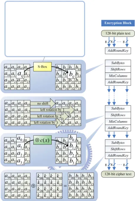
algorithm implements four transformations that operate on elements, rows and columns of the array respectively. After an initial round key addition, a round function consisting of four transformations, SubBytes(), ShiftRows(), MixColumns()
and AddRoundKey(), is applied to the State array. The round function is performed
10 times iteratively for 128-bit key, 12 times for 192-bit key and 14 times for 256-bit key. In the last round, MixColumns() is not applied. Four basic transformations of the AES algorithm are described briefly as follows [6]:
1. SubBytes() transformation, also called S-Box, is a non-linear byte substitution that
operates independently on each byte of the State. Given an element of the State
array, a ,ij 0≤ ji, ≤3, it is treated as the element in GF(28) with the irreducible
polynomial m(x). The SubBytes() transformation performs an inverse mapping of
ij
a first followed by an affine transformation. The SubBytes() can be expressed as
the following equation:
bij =(Affine(x)⋅aij 1)⊕const(x)
−
where Affine(x), const(x) are two polynomial in GF(2) with the degree less than 8. In AES algorithm, ( )= 8 + 4 + 3 + +1 x x x x x p
or {11B} in hexadecimal representation, and
( )= 4 + 3 + 2 + +1 x x x x x Affine = {1F} ( )= 6 + 5 + +1 x x x x const = {63}.
respectively. For the inverse of SubBytes() transformation, it can be obtained by the inverse of the affine transformation followed by taking the multiplicative
inverse in (28)
GF , i.e.,
Inv_Affine(x)=x6 +x3 +x = {4A}
_ ( )= x2 +1
x const
Inv = {05}.
2. ShiftRows() transformaion is simply a cyclic shifting operation on the rows of the
State with different numbers of bytes (offsets). In the State array, Row 0
(a ,00 a ,01 a ,02 a ) is not shifted, Row 1 (03 a ,10 a11,a12,a ) is left shifted over 1 byte, 13
Row 2 (a ,20 a21,a22, a ) is left shifted over 2 bytes and Row 3 (23 a ,30 a ,31 a ,32 a ) 33
shifting the Row 1, Row 2 and Row 3 over 1, 2 and 3 bytes respectively.
3. MixColumns() transformation is the operation that considers the column of State
as polynomials over (28)
GF , and performs the multiplication modulo (x4 +1)
with a fixed polynomial c(x). Let 3
3 2 2 1 0 ) (x a a x a x a x aj = j + j + j + j be a
polynomial with coefficients being the elements of the j-th columns of the State
array. Let 3 3 2 2 1 0 ) (x c c x c x c x
c = + + + be a polynomial with coefficient
) 2
( 8
GF
ci∈ ,0≤ i≤3. The matrix multiplication of MixColumns() transformation
can be expressed as the implementation of each column by c(x), i.e., bj(x)=aj(x)⋅c(x) mod (x4 +1), 0≤ j≤3.
in AES algorithm, c(x) is defined as {02} {01} {01} 2 {03} 3
x x
x+ +
+ . It can also be
written as the following matrix multiplication.
⎥ ⎥ ⎥ ⎥ ⎥ ⎦ ⎤ ⎢ ⎢ ⎢ ⎢ ⎢ ⎣ ⎡ ⋅ ⎥ ⎥ ⎥ ⎥ ⎦ ⎤ ⎢ ⎢ ⎢ ⎢ ⎣ ⎡ = ⎥ ⎥ ⎥ ⎥ ⎥ ⎦ ⎤ ⎢ ⎢ ⎢ ⎢ ⎢ ⎣ ⎡ j j j j j j j j a a a a b b b b 3 2 1 0 3 2 1 0 02 01 01 03 03 02 01 01 01 03 02 01 01 01 03 02
The inverse of MixColumns() transformation is similarly by multiplying each column with a specific multiplication polynomial d(x), which is defined by
c(x)⋅ xd( )=01. Thus ( ) {0 } {09} {0 } 2 {0 } 3 x B x D x E x d = + + + .
4. AddRoundKey() transformation is simply an XOR operation that adds a round key
to the State in each iteration, where the round keys are generated from the key expansion procedure.
⊕ 00 a 10 a 20 a 30 a 01 a 11 a 31 a 21 a 02 a 12 a 32 a 22 a 03 a 13 a 33 a 23 a 00 b 10 b 20 b 30 b 01 b 11 b 31 b 21 b 02 b 12 b 32 b 22 b 03 b 13 b 33 b 23 b 00 k 10 k 20 k 30 k 01 k 11 k 31 k 21 k 02 k 12 k 32 k 22 k 03 k 13 k 33 k 23 k = 00 a 10 a 20 a 30 a 01 a 11 a 31 a 21 a 02 a 12 a 32 a 22 a 03 a 13 a 33 a 23 a 00 b 10 b 20 b 30 b 01 b 11 b 31 b 21 b 02 b 12 b 32 b 22 b 03 b 13 b 33 b 23 b j
a
0 ja
1 ja
2 ja
3 jb
0 jb
1 jb
2 jb
3 ) (x c ⊗ 00 a 10 a 20 a 30 a 01 a 11 a 31 a 21 a 02 a 12 a 32 a 22 a 03 a 13 a 33 a 23 a 00 a 10 a 20 a 30 a 01 a 11 a 31 a 21 a 02 a 12 a 32 a 03 a 10 a 00 a 10 a 20 a 30 a 01 a 11 a 31 a 21 a 02 a 12 a 32 a 22 a 03 a 13 a 33 a 23 a 00 b 10 b 20 b 30 b 01 b 11 b 31 b 21 b 02 b 12 b 32 b 22 b 03 b 13 b 33 b 23 b ijb
ija
⎥ ⎥ ⎥ ⎥ ⎥ ⎥ ⎥ ⎥ ⎥ ⎥ ⎥ ⎦ ⎤ ⎢ ⎢ ⎢ ⎢ ⎢ ⎢ ⎢ ⎢ ⎢ ⎢ ⎢ ⎣ ⎡ + ⋅ ⎥ ⎥ ⎥ ⎥ ⎥ ⎥ ⎥ ⎥ ⎥ ⎥ ⎥ ⎦ ⎤ ⎢ ⎢ ⎢ ⎢ ⎢ ⎢ ⎢ ⎢ ⎢ ⎢ ⎢ ⎣ ⎡ = − 0 1 1 0 0 0 1 1 1 1 1 1 1 0 0 0 0 1 1 1 1 1 0 0 0 0 1 1 1 1 1 0 0 0 0 1 1 1 1 1 1 0 0 0 1 1 1 1 1 1 0 0 0 1 1 1 1 1 1 0 0 0 1 1 1 1 1 1 0 0 0 1 1 ij ij a bFig. 2.2 The encryption procedure of AES algorithm.
The decryption procedure of the AES is basically the inverse of each of the transformation (InvSubBytes(),InvShiftRows(),InvMixColumns(), and AddRoundKey() ) in reverse order.
The key expansion procedure in AES algorithm is used to calculate the round key for every AddRoundKey() transformation. Basic procedure of the key expansion is
shown in Fig. 2.3. According to the selected key size, N is 4 for 128-bit key, 6 for k
192-bit key and 8 for 256-bit key. Each W is a 32-bit word. The first i N words k
iteratively by SubBytes() transformation and cyclic byte rotation. The SubWord() is a function that return a 4-byte word where each byte is the result of SubBytes() transformation to the byte at the corresponding position in the input word. RotWord() performs a cyclic left rotation of a given word by 8 bits. Rcon(x) is a constant
composed by 4 bytes, {Rc ,{00}.{00},{00}}, where i
i i x
Rc = is the field element in
) 2
( 8
GF with polynomial m(x).
Fig. 2.3 Pseudo code of key expansion.
2.2 Block Cipher Modes of Operation
In cryptography, a block cipher operates on blocks of fixed length, often 64 or 128 bits. To encrypt longer messages, several modes of operation, such as Electronic Code Book (ECB), Cipher Block Chaining (CBC), Cipher Feedback (CFB), and Output Feedback (OFB) may be used. In the following, ECB and CBC modes, which can be supported by our C-AES coprocessor, are introduced.
1. Electronic Codebook mode (ECB)
When this cipher mode is used, each block is encrypted individually. No
feedback is used. This means any blocks of plaintext that are identical and are either in the same message, or in a different message that is encrypted with the same key, will be transformed into identical ciphertext blocks. If the plaintext to
be encrypted contains substantial repetition, then it is feasible for the ciphertext to be broken one block at a time. Furthermore, it is possible for an unscrupulous person to substitute and exchange individual blocks without detection. The encryption procedure in ECB mode is described in Fig. 2.4.
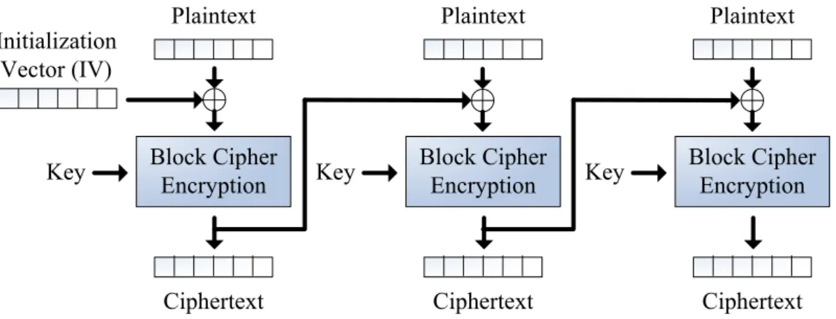
Fig. 2.4 The encryption procedure in ECB mode. 2. Cipher Block Chaining mode (CBC)
This cipher mode introduces feedback. Before each plaintext block is encrypted, it is combined with the ciphertext of the previous block by a bitwise XOR. This ensures that even if the plaintext contains many identical blocks, they will each encrypt to a different ciphertext block. As Fig. 2.5 shown, the initialization vector (IV) is combined with the first plaintext block by a bitwise XOR before the block is encrypted.
Block Cipher Encryption
Plaintext
Ciphertext
Key Block Cipher Encryption
Plaintext
Ciphertext
Key Block Cipher Encryption
Plaintext
Ciphertext Key
Initialization Vector (IV)
Chapter 3
Hardware-Reduction Strategy for C-AES
In general, the parameters of each transformation in the original AES algorithm are constants, so the optimization methods for hardware implementation of the configurable AES algorithm will be based on different consideration from previous works. The design of SubBytes() and MixColumns() transformations which provide the configurability and excellent trade-off between silicon area and performance will become the key point to be evaluated especially.
3.1 Previous Work
In AES proposal[5] , the authors describe the cipher Rijndael and treat the implementation aspects of the cipher and its inverse. They concentrate on the implementation in software on 8-bit processors, typical for current Smart Cards and on 32-bit processors, typical for PCs. The several performance comparisons of these implementations in software are estimated.
However, hardware implementations of AES algorithm compare to software implementations. They provide more physical security as well as higher speed. Since there is a need to perform data encryption on high-speed network services, the operation speed is very important. Many architecture optimization approaches are employed to speed up the hardware implementations. According to the approaches used to implement the SubBytes() transformations (also known as the S-Box) , we can divide these into two kinds : look-up table (LUT) based designs and non-LUT based designs.
The traditional LUT methodology is well suited to implement the complex and slow operations. Especially, it is cost-effective for the field programmable gate arrays
(FPGAs) [7][8][9][10][11][12]. In particular, several approaches merge the SubBytes() and MixColumns() transformation into a single LUT for an additional speedup [13][14][15][16]. The high speeds can be achieved by a 10-stage fully pipelined LUT based Rijndael encryption design [17]. However, the encryption and decryption processes need implementing as separate LUTs, and these approaches lead to high area requirements.
Non-LUT approaches employ the combinational logic only to implement the multiplicative inverse and the affine transformation of S-Box. Since the inversions in
Galois Field GF(28) have high hardware complexities, the field elements of
) 2
( 8
GF are mapped to the elements in some isomorphic composite fields, in which
the field operations can be implemented by lower cost subfield operations. Compared to the LUT-based approach, the composite field arithmetic has cost-benefit for the semi-custom application specific integrated circuit (ASIC) implementations. The approaches based on this idea can be found in [18][19][20][21]. In particular, Authors of [22][23] have evaluated the sub-pipelined architecture based on optimum speed-area ratio in non-feedback modes.
3.2 S-Box Optimization
Since our goal is to propose a configurable AES coprocessor. If the LUT-based approach is used to implement the S-Box, any change of the Affine matrix, const(x) and m(x) will require a replacement for the S-Box values. For example, if we use
ROM-based LUT, it needs another 256×8-bit ROM to store one set of the S-Box
values. It is unacceptable area requirement to support parameter configurability; else if we use RAM-based LUT to transfer S-Box values, either to re-compute these values on chip or off chip will consume a long configuration time. Therefore, we select the composite field arithmetic approach to implement S-Box. Since it only requires
16
2× 8-bit matrix multiplier to provide the configurability of Affine matrix, const(x)
and m(x). The area requirement can be reduced to an acceptable area, and the critical path also can be modified by combining the data path of sub-functions. In the following sections, two techniques, composite field arithmetic and combination of
3.2.1 Composite Field Arithmetic
We call two pairs { (2n)
GF ,
∑
− = + = 1 0 ) ( n i i i n y q y y Q , qi∈GF(2) } and { ((2n)m) GF ,∑
− = + = 1 0 ) ( m i i i m x p x x P ,pi∈GF(2n)} a composite field [26], if ● (2n)GF is constructed by Q( y), which is an irreducible polynomial of
degree n over GF(2);
● ((2n)m)
GF is constructed by P(x), which is an irreducible polynomial
of degree m over (2n)
GF .
Moreover, the composite field ((2n)m)
GF is isomorphic to the field GF(2k)
for k=nm. According the investigation of a lot of fields [23], the following irreducible
polynomials are selected to extend the composite field of (28)
GF in our design. ⎪⎩ ⎪ ⎨ ⎧ = + + = + + = }) 1001 { ( ) ( : ) ) 2 (( 1 ) ( : ) 2 ( 2 1 2 4 4 0 4 ω ω x x x q GF x x x q GF (3.1) Additionally, the composite fields can be built iteratively from the lower order
fields. As shown in [19] , the composite field of (28)
GF also can be extended under
the polynomial basis using these irreducible polynomials:
⎪ ⎪ ⎩ ⎪⎪ ⎨ ⎧ = + + = = + + = + + = ) } 1100 { ( ) ( : ) ) ) 2 ((( ) } 10 { ( ) ( : ) ) 2 (( 1 ) ( : ) 2 ( 2 2 2 2 2 2 2 2 1 2 2 2 0 2 λ λ φ φ x x x p GF x x x p GF x x x p GF (3.2)
Fig. 3.1 shows the outline of the S-Box implementation by using the composite field arithmetic. The multiplicative inversion over a field A is the most costly operation. The following 3 steps are adopted to implement this operation.
1. Map all elements of the field A to a composite field B, using an
isomorphism functionδ .
2. Compute the multiplicative inverses over the field B.
δ ((2 ) ) m n GF ) 2 ( n GF ) 2 ( GF 1 − δ δ ((2 ) ) m n GF ) 2 ( n GF ) 2 ( GF 1 − δ
Fig. 3.1 The outline of the S-Box implementation
3.2.2 Isomorphism Functions and Basis Transformation
The isomorphism function is the transformation matrix to map elements of )
2
( k
GF to GF((2n)m). The method for generating the transformation matrix can be
found in [19][27][28] for the condition where the field polynomials are primitive
polynomials. Although, the polynomial 8+ 4+ 3+ +1
x x x
x {11B} used in the AES
algorithm is an irreducible polynomial but is not primitive. The exhaustive-search -based algorithm in [28] can be used to find the transformation in this case, and the
primitive irreducible polynomial ( )= 8 + 4 + 3 + 2 +1
x x x x x p {11D} is the better
choice to be the basis in the composite field [19][23][29].
The δ and δ−1 matrices which map (28)
GF into )GF((24)2 and
) ) 2
(( 4 2
GF into GF(28) based on the field polynomial in (3.1) are as below.
⎥ ⎥ ⎥ ⎥ ⎥ ⎥ ⎥ ⎥ ⎥ ⎥ ⎥ ⎦ ⎤ ⎢ ⎢ ⎢ ⎢ ⎢ ⎢ ⎢ ⎢ ⎢ ⎢ ⎢ ⎣ ⎡ = 1 0 1 0 0 0 0 0 1 1 0 1 1 1 1 0 1 0 1 0 1 1 0 0 1 0 1 0 1 1 1 0 1 1 0 0 0 1 1 0 1 0 0 1 1 1 1 0 0 1 0 1 0 0 1 0 0 1 0 0 0 0 1 1 δ ⎥ ⎥ ⎥ ⎥ ⎥ ⎥ ⎥ ⎥ ⎥ ⎥ ⎥ ⎦ ⎤ ⎢ ⎢ ⎢ ⎢ ⎢ ⎢ ⎢ ⎢ ⎢ ⎢ ⎢ ⎣ ⎡ = − 1 1 1 0 0 0 1 0 0 1 0 0 0 1 0 0 0 1 1 0 0 0 1 0 0 1 1 1 0 1 1 0 0 0 1 1 1 1 1 0 1 0 0 1 1 1 1 0 0 0 1 1 0 0 0 0 0 1 1 1 0 1 0 1 1 δ (3.3)
The δ and δ−1 matrices which map (28) GF into )GF(((22)2)2 and ) ) ) 2 ((( 2 2 2
GF into GF(28) based on the field polynomial in (3.2) are as below. The
least significant bits are in the upper left corner.
⎥ ⎥ ⎥ ⎥ ⎥ ⎥ ⎥ ⎥ ⎥ ⎥ ⎥ ⎦ ⎤ ⎢ ⎢ ⎢ ⎢ ⎢ ⎢ ⎢ ⎢ ⎢ ⎢ ⎢ ⎣ ⎡ = 1 0 1 0 0 0 0 0 1 0 1 0 1 1 0 0 1 1 0 1 0 0 1 0 0 1 1 1 0 0 0 0 1 1 0 0 0 1 1 0 0 1 0 1 0 0 1 0 0 0 0 0 1 0 1 0 1 1 0 1 1 1 0 1 δ ⎥ ⎥ ⎥ ⎥ ⎥ ⎥ ⎥ ⎥ ⎥ ⎥ ⎥ ⎦ ⎤ ⎢ ⎢ ⎢ ⎢ ⎢ ⎢ ⎢ ⎢ ⎢ ⎢ ⎢ ⎣ ⎡ = − 0 0 1 0 0 1 0 0 1 1 1 0 1 1 1 0 1 0 1 0 0 1 0 0 0 1 0 1 1 0 1 0 1 0 1 1 0 0 1 0 0 1 1 1 0 0 1 0 1 0 1 1 0 0 0 0 0 1 0 1 0 0 0 1 1 δ (3.4)
However, in order to support the configurability of the irreducible polynomial
m(x) in the S-Box and to use the previous isomorphism functions directly, it is
necessary to perform the change of basis on the common (28)
GF field. Based on
the algorithms in [30][31], they proposed the efficiently operation to calculate the
change-of-basis matrix from Basis B1 to B on the common field degree. 0
Therefore we can convert our field element which modulo another m(x) into the basis used in the isomorphism functions.
For example, if we suppose that B is the polynomial basis modulo 0
1 )
( 8 4 3
0 x = x +x +x +x+
m {11B}, and B1 is the polynomial basis modulo
1 )
( 8 7 6 5 2
1 x =x +x +x +x +x +
m {1F5}, which is another irreducible polynomial
m(x). According the arithmetic operations in [30][31], the change-of-basis from B1 to B is 0 Γ and the inverse matrix from B to 0 B1 is Γ . −1
⎥ ⎥ ⎥ ⎥ ⎥ ⎥ ⎥ ⎥ ⎥ ⎥ ⎥ ⎦ ⎤ ⎢ ⎢ ⎢ ⎢ ⎢ ⎢ ⎢ ⎢ ⎢ ⎢ ⎢ ⎣ ⎡ = Γ 1 1 1 1 1 1 0 1 0 1 1 0 0 1 1 1 1 1 1 1 1 0 1 0 1 0 0 0 0 1 1 0 0 0 1 1 0 1 0 0 0 1 1 0 1 0 0 1 0 0 1 0 0 0 1 1 0 0 0 0 0 0 0 1 ⎥ ⎥ ⎥ ⎥ ⎥ ⎥ ⎥ ⎥ ⎥ ⎥ ⎥ ⎦ ⎤ ⎢ ⎢ ⎢ ⎢ ⎢ ⎢ ⎢ ⎢ ⎢ ⎢ ⎢ ⎣ ⎡ = Γ− 1 0 1 1 0 0 0 1 1 1 0 1 1 1 0 1 0 0 1 1 1 1 0 1 1 0 1 0 1 0 1 0 1 1 1 0 0 1 0 1 1 0 0 1 1 1 1 1 0 0 1 1 1 1 1 0 0 0 0 0 0 0 0 1 1 (3.5)
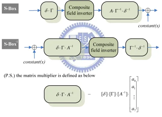
Therefore, the modification of the S-Box implementation is shown in Fig. 3.2. As
the irreducible polynomial m(x) is changed, The δ and δ−1 are replaced with
(δ⋅Γ) and (Γ−1 ⋅δ−1). We define the δ′=δ ⋅Γ and δ′−1 =Γ−1⋅δ−1 as the new
isomorphism functions for configurable S-Box in the following section. Because the affine transformation and the isomorphism are all linear operation, it is possible to
merge them together to reduce the path delay. Thus, the values of (δ′⋅A) and
( ⋅δ′−1
A ) can be computed before the encryption or the decryption operations. In fact,
we process the parameter initialization when the input interface receives the parameter data concurrently. The parameter initialization will be described in the Chapter 5. Moreover, we can reuse the inversion over the composite field for different
m(x), Affine matrix and constant(x) easily with the help of parameter initialization.
1 − ⋅ Γ ⋅ A δ Γ ⋅ δ ⋅Γ−1⋅δ−1 A 1 1 − − ⋅ Γ δ 1 − ⋅ Γ ⋅ A δ ⎥ ⎥ ⎥ ⎥ ⎥ ⎥ ⎦ ⎤ ⎢ ⎢ ⎢ ⎢ ⎢ ⎢ ⎣ ⎡ ⋅ ⋅ Γ ⋅ − 7 1 0 1] [ ] [ ] [ a a a A δ
Fig. 3.2 The outline of the configurable S-Box implementation.
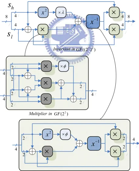
3.2.2 Multiplicative Inversion over the Composite Field
For the composite field ((2m)n)
GF , computing the multiplicative inverses can
be done as a combination of operations over the subfields (2m)
GF , using the
Extended Euclidean Algorithm described in [32]. Taking our proposed
implementation as an example, in the composite field ((24)2)
irreducible polynomials (3.1), an element can be expressed as S(x)=shx+sl, where h
s ,sl∈GF(24), and x is the root of q1(x). The multiplicative inverse of shx+ sl
modulo q1(x) is equivalent to B(x) which satisfying the follow equation [33]:
1 ) ( ) ( ) ( ) (x q1 x +B x S x = A (3.6)
Such A(x) and B(x) can be found by using the extended Euclidean algorithm. Firstly,
we need to rewrite q1(x) in the form of
) ( ) ( ) ( ) ( 1 x Q x S x R x q = + (3.7)
Q(x) and R(x) are the quotient and remainder polynomial of dividing q1(x) by S(x). By long division it can be derived as follow:
1 1 1 ) 1 ( ) (x =sh− x+ +sh− sl sh− Q (3.8) l h l h s s s s x R( )=ω+(1+ −1 ) −1 (3.9)
Substituting (3.8) and (3.9) into (3.6) and multiplying 2
h
s to both sides of the
equation, it follows that
) ( ) ( )) ( ( ) ( 2 2 1 2 l l h h l h h h q x s x s s S x s s s s s = + + + ω+ + (3.10) Multiplying 2 2 1 ) ( + + − =
Θ sh ω shsl sl to both sides of (3.10), we get
1 ) ( )) ( ( ) ( 1 2 =Θ + + + Θsh q x shx sh sl S x (3.11)
Since addition and subtraction are the same in the extended field of GF(2),
comparing (3.6) and (3.11), it can be observed that
Θsh2q1(x)+Θ(shx+(sh +sl))S(x)=1 −1( )= ( )= Θ +( + )Θ l h h x s s s x B x S (3.12)
According to (3.12), the multiplicative inversion in (28)
GF can be implemented in
) ) 2
(( 4 2
2
x
×ω 1 −x
×
×
×
hs
ls
Fig. 3.3 The multiplicative inversion based on composite field ((24)2)
GF .
For introducing the sub-operations in Fig. 3.3, let the elements in (24)
GF is
represented as polynomial of degree 4, i.e., =
∑
3= =∑
=0 3 0 ) ( , ) ( i i i i i ix B x b x a x A where ) 2 ( ,b GF
ai i∈ . Therefore, the hardware optimization of these sub-operations can be
obtained by using the following equations.
) ( ) ( ) ( 2 2 2 0 1 3 3 3 2 a a x a x a a x a x A = + ⊕ + + ⊕ (3.13) ) ( ) ( 2 2 1 0 3 3 0x a x a x a a a x A ×ω = + + + ⊕ (3.14)
In particular, the combination of the squarer ( 2
x ) and the constant multiplier (×ω)
can be cost-effective as (3.15). 0 1 3 2 3 3 0 0 2( ) ( ) ( ) a x a a x a x a a x A ×ω= ⊕ + + ⊕ + (3.15)
And the multiplication of these two field elements can be expressed as (3.16). By extracting the common factors in the bit-level expressions, we can apply the combination and integration of sub-factors for further area reduction.
} { } ) ( ) ( ) ( { } ) ( ) ( { } ) ( { ) ( ) ( 3 1 2 2 1 3 0 0 3 2 1 2 3 2 1 3 0 0 1 2 3 3 2 2 3 0 1 1 0 2 3 3 3 0 2 1 1 2 0 3 b a b a b a b a x b a a b a a b a a b a x b a a b a a b a b a x b a a b a b a b a x B x A ⊕ ⊕ ⊕ + ⊕ ⊕ ⊕ ⊕ ⊕ ⊕ + ⊕ ⊕ ⊕ ⊕ ⊕ + ⊕ ⊕ ⊕ ⊕ = × (3.16)
The most complicated operation in Fig. 3.3 is the inversion in (24)
GF . As the
definition of the field element in (24)
GF , the inversion of A(x) is equivalent to
) (
14 x
A . Thus, our approach simplifies the equation A−1(x)=A14(x) directly based
)} ( ) ( ) ( ) ( { )} ) ( ) ( { )} ( ) ( ) ( { } ) ( ) ( { ) ( ) ( 3 2 1 0 3 2 1 0 1 0 2 3 1 0 3 3 2 1 2 1 0 2 3 2 3 2 3 0 2 1 0 3 3 2 1 3 2 1 3 2 1 3 14 1 a a a a a a a a a a a x a a a a a a a a a a x a a a a a a a a a x a a a a a a a a a a x A x A ⊕ ⊕ ⊕ ⊕ ⊕ ⊕ ⊕ + ⊕ ⊕ ⊕ ⊕ ⊕ + ⊕ ⊕ ⊕ ⊕ ⊕ + ⊕ ⊕ ⊕ ⊕ ⊕ ⊕ = = − (3.17)
3.2.3 The Comparison of Multiplicative Inversion
Observing other approaches, the multiplicative inversion can be implemented by different irreducible polynomials to analyze the area cost and path delay. In [19], the authors use the (3.2) as their irreducible polynomials, and the implementation of the
inversion in ((22)2) GF is described in Fig. 3.4. 2
x
×λ 1 −x
×
×
×
hs
ls
×
×
×
φ × ) 2 ( 2 GF 2x
×φ 1 −x
×
×
×
) 2 ( 2 GF ) ) 2 (( 2 2 GFFig. 3.4 The implementation of the inversion in (((22)2)2)
However in [22], the inversion in ((22)2)
GF is directly implemented by (3.18)
using sub-expression sharing, not the multiple decomposition as described in Fig. 3.4. Moreover, it has the smallest gate count and the shortest critical path.
} { } { } { } { ) ( 0 1 0 1 2 1 2 2 0 3 0 1 3 1 3 0 2 3 1 2 3 1 0 2 2 0 1 3 1 2 3 3 2 1 2 2 0 3 0 2 3 1 2 3 3 2 0 3 1 2 3 3 1 a a a a a a a a a a a a a a a a a a a a a x a a a a a a a a a a a x a a a a a a a a a a a x a a a a a a a x B ⊕ ⊕ ⊕ ⊕ ⊕ ⊕ ⊕ ⊕ ⊕ + ⊕ ⊕ ⊕ ⊕ ⊕ + ⊕ ⊕ ⊕ ⊕ + ⊕ ⊕ ⊕ = − (3.18)
The comparison results of the individual composing modules are listed in Table 3.1. Observing the results in [19][22], composite field decomposition can reduce the hardware complexity significantly when the order of the field involved is large.
However, for a small field, such as (24)
GF , further decomposition may not be the
optimum approach. For this reason, we select the approach that implement the derived
equation by the common sub-expression sharing techniques in ((24)2)
GF .
Table 3.1 Performance analysis of the inversion in section 3.2.3.
ω λ × × 2 2 x x ) ) 2 (( ) 2 ( 2 2 4 GF GF ) ) 2 (( ) 2 ( 2 2 4 GF GF ) ) ) 2 ((( ) ) 2 (( 2 2 2 2 4 GF GF
In Table 3.1, the comparison between ours and the similar approach in [34] is also illustrated. In [34], a different irreducible polynomial (3.19) is be used to extend
the composite field ((24)2)
GF . The multiplicative inversion also can be found by
using the extended Euclidean algorithm, and the authors illustrate a new algorithm of common sub-expression elimination (CSE) to optimize the hardware cost of all the bit-level equations. Although another irreducible polynomial is applied, the difference in the hardware cost is limited.
⎪⎩ ⎪ ⎨ ⎧ = = + + = + + = }) 1001 { ( ), 0001 ( ) ( : ) ) 2 (( 1 ) ( : ) 2 ( 2 1 2 4 4 0 4 ω ω γx r x x q GF x x x q GF (3.19)
3.3 MixColumns() Optimization
In general, the multiplication of two elements of (28)
GF is required in
MixColumns(), and it is achieved by repeating xtime(). Since the implementation of xtime() function is based on the value of irreducible polynomial m(x), the changeable m(x) and MixColumns matrix will increase the complexity of multiplication
significantly in MixColumns().
Therefore, in our proposed approach, after the irreducible polynomial m(x) and
the MixColumns matrix C are given, the value of n( i)
c
xtime will be calculated in
advance and be stored in 4×8 8-bits registers, where c is the entry of i
MixColumns matrix, and i∈{0,1,2,3}. In the following, we take the operation of one
column (3.20) in MixColumns() as an example to describe our approach.
⎥ ⎥ ⎥ ⎥ ⎥ ⎦ ⎤ ⎢ ⎢ ⎢ ⎢ ⎢ ⎣ ⎡ ⋅ ⎥ ⎥ ⎥ ⎥ ⎦ ⎤ ⎢ ⎢ ⎢ ⎢ ⎣ ⎡ = ⋅ = 3 2 1 0 0 3 2 1 1 0 3 2 2 1 0 3 3 2 1 0 ) ( ) ( s s s s c c c c c c c c c c c c c c c c x s C x t (3.20)
) ( 0 ) ( 1 ) ( 0 ) ( 1 ) ( 0 ) ( 0 ) ( 1 ) ( 1 ) 0 ( 0 0 0 2 0 3 0 4 0 5 0 6 0 7 0 c c xtime c xtime c xtime c xtime c xtime c xtime c xtime CA c ⋅ + ⋅ + ⋅ + ⋅ + ⋅ + ⋅ + ⋅ + ⋅ = × ⋅ (3.21)
In other words, let the elements s is represented as polynomial of degree 8, i.e., 0
00 01 2 02 3 03 4 04 5 05 6 06 7 07 0 s x s x s x s x s x s x s x s
s = + + + + + + + , and (3.21) can rewrite as
follow. Thus, the multiplication in (28)
GF can be implemented by one 8-bit matrix
multiplier.
⎥
⎥
⎥
⎥
⎥
⎥
⎥
⎥
⎥
⎥
⎥
⎦
⎤
⎢
⎢
⎢
⎢
⎢
⎢
⎢
⎢
⎢
⎢
⎢
⎣
⎡
07 06 05 04 03 02 01 00s
s
s
s
s
s
s
s
=
⋅
=
⋅
0 0 0 0s
C
s
c
c ) (0 0 c xtim e)
(
0 1c
xtim
e
)
(
0 2c
xt
im
e
) (0 7 c xt im e⎥
⎥
⎥
⎦
⎤
⎢
⎢
⎢
⎣
⎡
(3.22) In summary, the configurability of MixColumns()/InvMixColumns() is providedby pre-computed and stored the C , c0 C , c1 C and c2 C in c3 4×8 8-bits registers.
In addition, MixColumns() and InvMixColumns() transformations can also easily share the same hardware by changing the coefficient according to the processing mode.
3.4 The Hardware Architecture
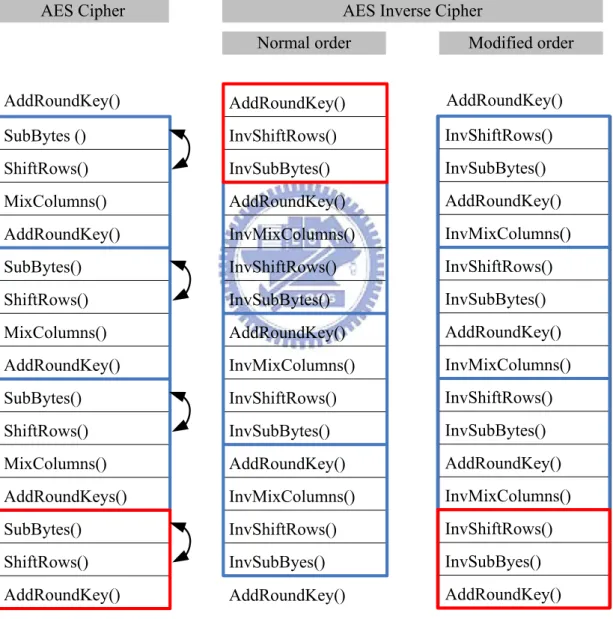
In this work, a half-duplex parameterized cipher engine is proposed. The encryption and decryption data paths are efficient combined based on the modified order in Fig. 3.5.
3.4.1 The Direct Architecture
Its direct architecture is depicted in Fig. 3.6. The solid line is the encryption path, and the dash line is the decryption path. The data procedure is a 128-bit architecture, i.e., 16 bytes are processed simultaneously. Based on the approach of composite field arithmetic, the finite field inverter and the matrix multipliers for field conversion are implemented, and the matrix multipliers are exploited to realize the MixColumns( ) /
InvMixColumns() transformation. SubBytes () ShiftRows() MixColumns() AddRoundKey() SubBytes() ShiftRows() MixColumns() AddRoundKey() SubBytes() ShiftRows() MixColumns() AddRoundKeys() SubBytes() ShiftRows() AddRoundKey() AddRoundKey() InvShiftRows() InvSubBytes() AddRoundKey() InvMixColumns() InvShiftRows() InvSubBytes() AddRoundKey() InvMixColumns() InvShiftRows() InvSubBytes() AddRoundKey() InvMixColumns() InvShiftRows() InvSubByes() InvShiftRows() InvSubBytes() AddRoundKey() InvMixColumns() InvShiftRows() InvSubBytes() AddRoundKey() InvMixColumns() InvShiftRows() InvSubBytes() AddRoundKey() InvMixColumns() InvShiftRows() InvSubByes() AddRoundKey() AddRoundKey() AddRoundKey() AddRoundKey()
AES Cipher AES Inverse Cipher
Normal order Modified order
Fig. 3.5 The operation order of encryption and decryption
Although these approaches have the benefit of on-line configurability, they will induce longer critical path than the traditional approaches[19][34]. Since the modular multiplications in original AES implementations are with constants, they can reduce
the area and shorten the path delay efficiently. Therefore, the approach that combines the matrix multipliers in the S-Box and MixColumns() transformation is proposed to reduce the computation path in our configurable Rijndeal design.
] [δ [δ⋅ A−1] ] [ ⋅δ−1 A [δ−1]
⊕
⊕
1 −x
⊕
⊕
⊕
Fig. 3.6 The direct architecture of parameterized cipher engine in this work.
3.4.2 The Combination of SubBytes() and MixColumns()
In this section, the combination of matrix multipliers in SubBytes() and
MixColumns() is introduced. Several representations are used to explain our approach
easily. In the following, Key(i) represents the key of i th round, and Key(0) is the initial key. According to the composite field arithmetic, SubBytes() transformation is
new isomorphism functions described in section 3.2.2, cA is const(x), and Inv() is
multiplicative inversion in (24)
GF , and Re(i)represents the intermediate values
produced after round function i times. Thus, the series transformations of encryption can be rewrote as follow:
) 0 ( ) 0 ( x Key Re = ⊕ (3.23) ) ( ) ))) 1 ( ( ( ( ) ( 1 i Key c i R ShiftRows Inv A MixColumns i Re = ⋅δ′− ⋅ δ′⋅ e − + A + 1 1≤i≤Nr− (3.24) ) ( ))) 1 ( ( ( ) ( 1 Nr Key c Nr R ShiftRows Inv A Nr Re = ⋅ ′ ⋅ ⋅′ e − + A+ − δ δ (3.25)
where Nr represents number of rounds, which is defined in Sec. 2.1.2.
Since our goal is to separate the affine transformation and the isomorphism function from S-Box and merge them with MixColumns(). In other words, (3.24) is
modified as (3.26), and the input of next round, Re(i) , will be redefined as
) ( ) (i R i Re′ =δ ⋅′ e , shown in (3.27). ) ( )) ))) 1 ( ( ( ( ( ) ( 1 1 i Key c A i R ShiftRows Inv A MixColumns i Re = ⋅δ′− ⋅ δ ⋅′ e − ⊕δ ⋅′ − ⋅ A ⊕ (3.26) ) ( ) ))) 1 ( ( ( ( ) ( )) ))) 1 ( ( ( ( ( ) ( ) ( 1 1 i Key c i R ShiftRows Inv s MixColumn i Key c A i R ShiftRows Inv A MixColumns i R i R A e A e e e ⋅′ ⊕ ′ ⊕ − ′ ′ = ⋅′ ⊕ ⋅ ⋅′ ⊕ − ′ ⋅ ′ ⋅ ⋅′ = ⋅′ = ′ − − δ δ δ δ δ δ (3.27) A c′ =δ′⋅A−1⋅cA (3.28) ) ( ) ( 1 x A MixColumns x s MixColumn ′ =δ′⋅ ⋅δ′− ⋅ (3.29)
Moreover, these parameters in (3.27) can be calculated beforehand to reduce the computation path delay. In particular, the new MixColumns() can be depicted as (3.29)
by the change of C′ , c0 C′ , c1 C′ , and c2 C′ , because the matrix multiplication of c3
MixColumns() transformation (3.22) can be rewrite as (3.30).
0 1 0 0 0 0 0 ) ( C A s s C s c c c ⋅ ′ ⋅ ⋅ ⋅ ′ = ⋅ ′ = ⋅ ′ − δ δ (3.30)
Although the initial round key addition (3.31) and the final round function (3.32) are also differing slightly from the traditional functions, the critical path is still dominated by the data path that computes one AES round function. Thus, comparing (3.27) and (3.24), the computation path of two 8-bit matrix multiplication is removed form the critical path after the optimized combination. The approach to optimize for speed requirement is achieved.
)) 0 ( ( ) 0 ( x Key Re′ =δ ⋅′ + (3.31) ) ( ) ))) 1 ( ( ( ( ) ( 1 Nr Key c Nr R ShiftRows Inv A Nr Re′ = ⋅ ′ ⋅ ⋅′ e′ − ⊕ ′A ⊕ − δ δ (3.32)
Using the same approach, the operation order of decryption in Fig. 3.5 can also
be represented as Rd(i), showed in (3.33)(3.34)(3.35), and the proof of the modified
intermediate value,Rd′(i), is given in (3.37)(3.39)(3.40).
) ( ) 0 ( x Key Nr Rd = + (3.33) 1 1 )) ( )) )) 1 ( ( ( ( ( ) ( 1 1 − ≤ ≤ − ⊕ ⊕ − ⋅ ⋅′ ⋅ ′ = − − Nr i i Nr Key c i R ws InvShiftRo A Inv mns InvMixColu i Rd δ δ d A (3.34) ) 0 ( )) )) 1 ( ( ( ( ) ( 1 1 Key c Nr R ws InvShiftRo A Inv Nr Rd =δ′− ⋅ δ′⋅ − ⋅ d − ⊕ A ⊕ (3.35) )) ( ) )) 1 ( ( ( ( ) ( 1 1 1 i Nr Key c A i R A ws InvShiftRo Inv mns InvMixColu i Rd d A − ⊕ ⋅ ⋅ ′ ⊕ − ⋅ ⋅ ′ ⋅ ′ = δ − δ − δ − (3.36) ) ( )) ))) 1 ( ( ( ( )}) ( ) )) 1 ( ( ( { ( )) ( ) )) 1 ( ( ( ( )) ( ) ( 1 1 1 1 1 1 1 1 1 i Nr Key c i R ws InvShiftRo Inv s mn InvMixColu i Nr Key c A i R A ws InvShiftRo Inv mns InvMixColu A i Nr Key c A i R A ws InvShiftRo Inv mns InvMixColu A i R A i R A d A d A d d d − ⋅′ ⊕ ′ ⊕ − ′ ′ = − ⋅′ ⊕ ⋅ ⋅′ ⊕ − ⋅ ⋅′ ⋅ ′ ⋅ ⋅′ = − ⊕ ⋅ ⋅′ ⊕ − ⋅ ⋅′ ⋅ ′ ⋅ ⋅′ = ⋅ ⋅′ = ′ − − − − − − − − − δ δ δ δ δ δ δ δ δ δ δ (3.37) ) ( ) ( 1 1 x mns InvMixColu A x s mn InvMixColu ′ =δ′⋅ − ⋅ δ′− ⋅ . (3.38) )) ( ( ) 0 ( 1 Nr Key x A Rd′ = ⋅ + − δ (3.39) )} 0 ( )) )) 1 ( ( (( { ) ( 1 Key c Nr R ws InvShiftRo Inv Nr Rd′ =δ′− ⋅ ′d − ⊕ ′A ⊕δ ⋅′ (3.40)
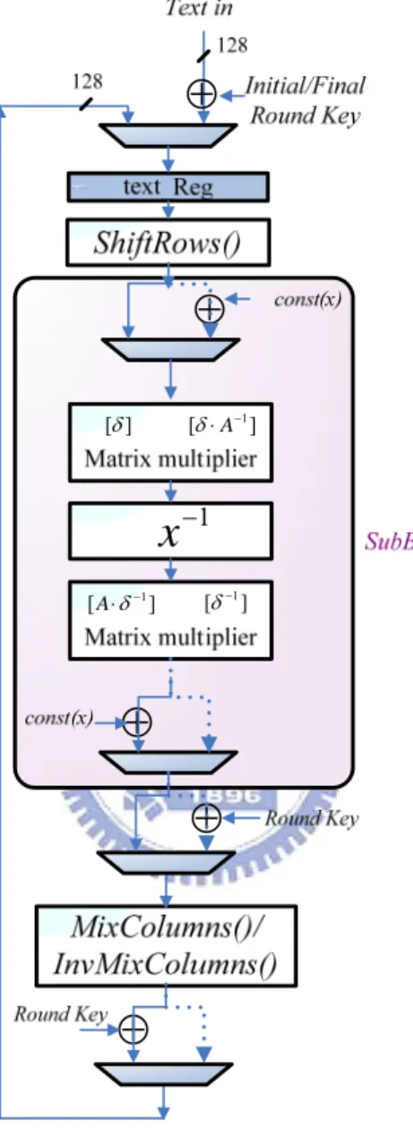
Taking the hardware resource shared between the encryption and the decryption into consideration, the circuit in Fig. 3.7 is an implementation according to the
equation of Re′(i) and Rd′(i). Note that the matrix multipliers which located at the
both ends of the multiplicative inversion are separated from the computation path of one AES round function.
⊕
1 −x
] [δ′ [δ′ A⋅ −1]⊕
A c A ⋅ ⋅ ′ −1 δ⊕
RoundKey ⋅′ δ A c A ⋅ ⋅ ′ −1 δ ] [A⋅δ′−1 ] [δ′−1 ] [δ′ [δ⋅ A−1]⊕
δ ⋅′RoundKey⊕
] [A⋅δ′ [δ′]Fig. 3.7 The combined architecture of the parameterized cipher engine.
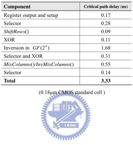
Our design is synthesized using the Synopsys Design Version. The critical path is
detailed in Table 3.2. The multiplicative inversion in (24)
GF occupies about 38% of
the delay time. The second major component is neither MixColumns() nor
the original Rijndael algorithm specification, where they appear as conditional branches and data selections. Because of the wide data width, the optimization of the data selection is considered carefully.
Table 3.2 The critical path of the cipher engine
Component Critical path delay (ns)
Register output and setup 0.17
Selector 0.28
ShiftRows() 0.09
XOR 0.11
Inversion in (24)
GF 1.68
Selector and XOR 0.31
MixColumns()/InvMixColumns() 0.55
Selector 0.14
Total 3.33
Chapter 4
3-in-1 Key Expansion Design
The key generator that generates the forward and reverse round keys for the encryption and the decryption is another issue needs to be considered. The on-the-fly key expansion is an approach that generates each round key in the operation time of each round function. Therefore, different from the pre-computation approach, it is unnecessary to use additional memory to store the sub-keys, and can support a better trade-off between cost and performance than others. In this approach, the key generator for 128-bit key size only is illustrated in [21][25] , and another one for three different key size is proposed in [35] .
In this chapter, the 3-in-1 key generator to cooperate with the cipher engine is proposed. Our design will produce one 128-bit round key per clock cycle for three different types of key length: 128-bit, 192-bit, and 256-bit. The basic architecture is made reference to [35], and an efficient architecture is proposed and the shorter critical path and lower area overhead is obtained by optimizing the order of data selection.
4.1 The Data Flow Graph of Key Expansion
According to AES algorithm specification and the representations in Fig. 4.1 [35], the data flow graphs for three different types of key length are derived in Fig. 4.2, Fig. 4.3, and Fig. 4.6. The details are described in the following sections.
x y z ] [ )) ( (Rot y Rcon i SBox x z= ⊕ ⊕ x y z ) ( y SBox x z= ⊕
y x
z= ⊕ z=x
Fig. 4.1 The representations of operation in key expansion.
4.1.1 128-bit Key Expansion
The initial cipher key is denoted by the array of 4-byte words, [w0, w1, w2, w3], and a single round function of key expansion is illustrated in Fig. 4.2. Since the number of rounds (Nr) is 10 when the key length is 128-bit, the final round key will be produced as [w40, w41, w42, w43], and this will be the initial input of key expansion in decryption procedure. Because the length of cipher key is equal to the length of the State array, it is quite straight forward to generate the round key for each clock cycle.
Fig. 4.2 The 128-bit key expansion for the encryption/decryption.
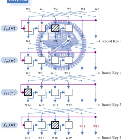
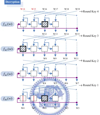
4.1.2 192-bit Key Expansion
The data flow is similar to the one described above, but the initial cipher key becomes the array of 6-byte words [w0, w1, w2, w3, w4, w5]. Moreover, the 192-bit key is concurrently computed for each cycle shown in Fig. 4.3. However, the length of round key required by the cipher engine is still 128-bit, not 192-bit. This different bit length will cause the incompatible timing diagram. In order to solve this problem, the key expansion routine is rearranged such that only one 128-bit round key are produced for each time frame. The results for the encryption and the decryption are demonstrated in Fig. 4.4 and Fig. 4.5. For the rearranged data flow graph, the new
round functions are represented as fR0(w) ,fR1(w), fR2(w), and fR3(w).
Fig. 4.3 The 192-bit key expansion for the encryption/decryption.
) ( 3 w fR ) ( 2 w fR ) ( 1 w fR ) ( 0 w fR
Fig. 4.4 The rearrangement of the 192-bit key expansion for the encryption. At the start of the key expansion for the encryption, which is shown in Fig. 4.4,
the initial cipher key applies the round function fR0(w) to produce next round key,
and go on. For the 192-bit cipher key, the number of rounds is 12. Thus, the final round key will be represented as [w48, w49, w50, w51], and output from the round
function fR2(w). For this reason, note that the first round function for the decryption
will be fR2(w), not fR0(w), and the following data flow can be easily found by
reversing the computing order.
W12 W13 W14 W15 W14 W15 W16 W17 W18 W19 Round Key 4 Round Key 3 Round Key 2 Round Key 1 Decryption W8 W9 W10 W11 W4 W5 W6 W7 W4 W5 W0 W1 W2 W3 ) ( 3 w fR ) ( 2 w fR ) ( 1 w fR ) ( 0 w fR
Fig. 4.5 The rearrangement of the 192-bit key expansion for the decryption.
4.1.2 256-bit Key Expansion
As described above, Fig. 4.6 shows the original data flow graph.
Observing the results of rearrangement shown in Fig. 4.7 and Fig. 4.8, it is more similar with 128-bit key expansion. The data flow of the encryption and the decryption are almost the same, since the first round function for decryption is still fR0(w). ) ( 2 w fR ) ( 1 w fR ) ( 0 w fR
Fig. 4.7 The rearrangement of 256-bit key expansion for the encryption.
W0 W1 W2 W3 W4 W5 W6 W7 W8 W9 W10 W11 W12 W13 W14 W15 W8 W9 W10 W11 Round Key 3 Round Key 2 Round Key 1 W4 W5 W6 W7 Decryption ) ( 0 w fR ) ( 1 w fR ) ( 2 w fR
Fig. 4.8 The rearrangement of 256-bit key expansion for the decryption.
In summary, by properly shuffling the input key for each round function, only 4 computing elements are used to realize the key expansion for different key length.