國立交通大學
資訊學院
資訊科學與工程研究所
博
士 論 文
利用環場視覺作自動車應用之定位與影像
分析新技術之研究
New Localization and Image Adjustment
Techniques Using Omni-Cameras for
Autonomous Vehicle Applications
研
究 生: 吳至仁
指
導 教 授: 蔡 文 祥 博士
ii
利用環場視覺作自動車應用之定位與影像
分析新技術之研究
New Localization and Image Adjustment
Techniques Using Omni-Cameras for
Autonomous Vehicle Applications
研
究 生 : 吳 至 仁 Student:
Chih-Jen
Wu
指
導 教 授 : 蔡 文 祥 博士 Advisor:
Dr.
Wen-Hsiang
Tsai
國 立 交 通 大 學 資 訊 學 院
資 訊 科 學 與 工 程 研 究 所
博 士 論 文
A Dissertation Submitted to
Institute of Computer Science and Engineering
College of Computer Science
National Chiao Tung University
in Partial Fulfillment of the Requirements for the Degree of
Doctor of Philosophy
in Computer and Information Science
June 2009
Hsinchu, Taiwan, 30010
Republic of China
iii
利用環場視覺作自動車應用之定位與影像分析新技術
之研究
研究生:吳 至 仁 指導教授: 蔡文祥博士
國立交通大學資訊學院
資訊科學與工程研究所
摘
要
許多自動車的應用中,定位是欲操控自動車所必備的功能。一個廣泛採用的 方法是利用電腦視覺來作自動車定位,其方法是藉由電腦分析攝影機所攝得的影 像來推算自動車本身的位置。近來新型態的環場攝影機漸漸被廣泛地應用在自動 車定位上。相較於傳統攝影機,環場攝影機寬廣的視角可讓更大的景物範圍出現 在視野中,更有助於利用視覺作定位的計算。然而,實際上環場攝影機擷取到的 影像是扭曲的,造成影像處理上的困難,使定位工作變得難以進行,因此需要進 行影像修正。 在本論文中,我們提出了一系列基於環場視覺的新的自動車定位與環場影像 修正技術,並將其應用在各種自動車的用途上。我們使用了雙曲面反射鏡式與魚 眼透鏡式的環場攝影機,而且,我們採用了路標式定位法,該法使用環境中明顯 路標來作自動車的定位。在另一方面,我們在環場影像上,直接分析基本的路標 幾何特徵(如直線與圓形等)的投影與投影之間的相互關係(如平行與垂直等)。 並將前述所提出的方法應用在多種自動車的導航上,包含室內自動車導航、直升iv 機降落、汽車輔助駕駛等。更進一步地,我們提出了解決影像定位技術應用在自 動車上常見的兩個問題的方法,一個是所謂扭曲環場影像的轉正方法,可用以解 決自動車震動所導致的影像扭曲,另一個是一所謂空間與影像間的對映方法,此 法可解決應用場合中攝影機重新安裝所導致的定位失效問題。這兩個方法讓前述 所提自動車定位方法在實際應用中變得更為有效。茲將前述所提各種方法分為兩 類⎯新自動車定位技術與新影像修正技術⎯詳細說明如下。 (A)針對自動車新定位技術 --- (a)我們提出了一個描述環場影像中的圓形路標投影的新方法。在此法中,我們 證明了此一投影可用橢圓來加以逼近,其中我們用了泰勒展開的技巧。以此, 我們得以提出一個新法則來抽取環場影像中的橢圓狀投影。 (b)我們提出了一個利用圓錐曲線來描述環場影像中的直線投影的新方法。在此 方法中我們推導出簡單而且有公式解的直線投影方程式,並接著提出可用以 從環場影像中抽取圓錐曲線的簡便方法,其原理乃基於赫夫轉換。 (c)我們提出了一個以環場影像中的天花板圓形圖案,作為路標的室內自動車定 位與導航之方法。此利用此路標具有容易偵測與辨識,且不易被遮蔽等優點。 (d)我們提出了一個利用環場影像中的 Y 形屋角影像,作為路標的室內自動車定 位與導航之方法。因為燈光或拍攝角度的關係,Y 形直角並非每次都能完整 的出現在環場影像中,所以我們分析了 Y 型屋角在環場影像中,所有可能出 現的樣式,如點、垂直線、水平線及其可能組合樣式,並分別提出相對應的 定位方法。 (e)我們提出了一個利用環場影像中的標準停機坪影像,作為路標的直升機降落 之定位方法。在充分且有效的分析環場影像中停機坪圖案的幾何特徵,包含
v 圓形、水平線,加以參考直升機距離停機坪的遠近,我們提出了包含接近、 對正與觸地的三階段定位方法。其中,求出的定位資訊包含高度、方位、與 距離。 (f)我們提出了一個利用環場影像中的小客車車輪影像,作車側車輛定位方法。 只要利用本身車輛上的一台環場攝影機所拍到的鄰車影像,再經分析中車輪 影像後,此方法即可推算出鄰車相對於本身車輛的位置及方向,並具有公式 解。 (B)針對新影像修正技術 --- (a)我們提出了一個針對非置中環場攝影機所拍攝的扭曲影像,將其轉正的方 法。造成非置中環場攝影機的現象,乃因在置中環場攝影結構中,原先的透 鏡/反射鏡相對位置改變。造成此一改變的原因,常常是因為自動車的震動或 攝影機的重新安裝。我們的方法可以當場解決此問題,而不必送回當初的攝 影機製造廠作校正。 (b)我們提出了一個可應用於物體定位或自動車定位的空間對映方法,並能在實 際應用時,適應攝影機高度與角度的改變。此方法基於空間對應表,可求出 於多種型攝影機的影像座標與空間座標的對應關係,使得面臨實際環境時, 該方法更加具有應用價值。 實驗結果顯示本論文提出的所有方法,皆具有優越性及有效性。最後,討論 與未來可能研究方向也附於本論文中。
vi
New Localization and Image Adjustment
Techniques Using Omni-Cameras for
Autonomous Vehicle Applications
Student: Chih-Jen Wu
Advisor: Dr. Wen-Hsiang Tsai
Institute of Computer Science and Engineering
College of Computer Science
National Chiao Tung University
Abstract
Vehicle localization is essential for autonomous vehicle guidance in many applications. A widely adopted approach is the vision-based technique by which the locations of vehicles can be computed by analyzing the images captured by cameras. Omni-cameras have become more and more popular recently for their wider field of views (FOVs).Wider FOVs make the job of localization easier because a larger scene range can be taken in a single shot. However, due to the distortion in the images taken by omni-cameras, it is difficult to use omni-cameras in vehicle localization applications unless taken omni-images are properly adjusted.
In this study, investigation of new omni-vision based vehicle localization techniques and omni-image adjustment, as well as their applications is conducted. Two types of omni-camera are used, including hyperboloidal omni-camera and fish-eye camera. Also, the landmark based approach to localization is adopted, in which obvious landmarks in vehicle navigation environments are utilized. On the
vii
other hand, the projections of basic landmark features (lines, circles, etc.) in omni-images, and their relations (parallelism, perpendicularity, etc.) are analyzed mathematically. Accordingly, methods for varoius vehicle localization applications using the basic landmark features are proposed, including indoor vehicle guidance, helicopter landing, car driving assistance, etc. Furthermore, solutions to two vehicle localization problems frequently encountered with in real applications are also proposed, one being an omni-image unwarping method for dealing with image distortions caused by a misaligned omni-camera, and the other being a space-to-image mapping method which is adaptive to camera setup changes found in in-field environments. These two solutions make the proposed vehicle localization methods more effective in real environments. The above-mentioned proposed methods are summarized in the following, classified into two categories: new vehicle localization techniques and image adjustment techniques.
A. New vehicle localization techniques
(a) A new method for describing the projection of a circular-shaped landmark in omni-images is proposed. It is shown that such a projection may be approximated by an ellipse based on the application of Taylor expansion. In accordance, a new algorithm is designed for extracting the elliptical-shaped projections from omni-images of circular-shaped landmarks.
(b) A new method for describing the projection of a line in an omni-image as a conic section is proposed. Equations of such a projection are derived to be simple and analytic, and consequently uncomplicated effective image analysis algorithms are designed for extracting such conic sections out of omni-images by the Hough transform.
viii
navigation in indoor environments using circular landmarks on ceilings is proposed. Such landmarks have several advantages can be identified, including ease to detect and recognize, and freedom from oclussion.
(d) Systematic vision-based vehicle localization techniques by hyperboloidal omni-cameras using Y-shaped house corners in indoor environments as landmarks are proposed. All possible partial structures of a house corner consisting of a corner point, a horizontal line, and a vertical one are considered, facilitating flexible vehicle localization under various lighting, occlusion, and imaging posture conditions.
(e) An omni-vision-based self-localization method for automatic helicopter landing on a helipad with a circled H-shape is proposed. The landing process includes three stages: approaching, alignment, and docking. Three types of image features, circle, line, and point, are used to derive skillfully analytic equations for computing the helicopter height, distance, and orientation with respect to the landing site.
(f) A lateral vehicle localization method by omni-image analysis is proposed for car driving assistance. The method estimates analytically the position and orientation of a lateral vehicle by utilizing the geometric properties of a circular-shaped wheel image of the lateral car taken by a single omni-camera.
B. Image adjustment techniques
(a) A new method for solving the problem of unwarping a distorted omni-image taken by a lateral-directionally misaligned omni-camera is proposed. Such camera misalignment is a frequently encountered problem of vision-based localization in real applications due to vehicle vibrations or camera redeployments. The method can solve this problem without camera calibration which is usually done in advance in the factory.
ix
(b) A new space-mapping method for object location estimation or vehicle localization, which is adaptive to camera setup changes in application environments is proposed. The method, which is general for various types of cameras, estimates the location of an object appearing in an image by mapping the image coordinates of an object point to the real-world coordinates of the point using a space-mapping table. Such a method makes the space-mapping based approach to object localization more useful to real applications.
Good experimental results are shown to prove the feasibility and effectiveness of all the proposed methods. Discussions on possible future research directions are also included.
x
Acknowledgements
I would like to express my sincere appreciation to my advisor, Professor Wen-Hsiang Tsai, for his patience and kind guidance throughout the course of this dissertation study and the invaluable training. Thanks are also extended to the colleagues in the Computer Vision Laboratory at National Chiao Tung University for their valuable help during this study.
Finally, I am so grateful to my wife and family for their love, support, and endurance. This dissertation is dedicated to them.
xi
Table of Contents
Chinese Abstract ... iii
English Abstract ... vi
Acknowledgements ... x
Table of Contents ... xi
List of Tables ... xvii
List of Figures ... xviiiii
Chapter 1
Introduction ... 1
1.1 Motivation of Study ... 1
1.2 Survey of Related Works ... 3
1.2.1 Survey of Types of Omni-cameras ... 4
1.2.2 Survey of Localization Methods for Different Vehicle Applications .. 7
1.2.3 Survey of Image Adaptation Methods for Adjusting Images Taken by Misaligned or Posture-Slanted Cameras ... 12
1.3 Contributions of This Study ... 14
1.4 Dissertation Organization ... 16
Chapter 2
Location Estimation for Indoor Autonomous Vehicle
Guidance by Omni-vision Using Circular Landmarks on
Ceilings ... 18
2.1 Idea of Proposed Method ... 18
2.2 Approximation of Irregular Shape in Omni-image Taken of Circular-shaped Landmark by Ellipse ... 20
xii
2.2.1 Approximation of Distorted Circular Shapes in Omni-images by
Ellipses ... 21
2.2.2. Effectiveness of Shape Approximation ... 27
2.3 Vehicle Location Estimation ... 28
2.3.1 Vehicle Location Estimation by Axis Lengths of Ellipse ... 29
2.3.2 Estimation of Vehicle Moving Distances and Orientation Changes .. 32
2.4 Experimental Results ... 33
2.5 Identification and arrangement of the proposed landmarks in real applications ... 39
2.6 Concluding Remarks ... 40
Chapter 3
A Systematic Approach to Indoor Vision-Based Robot
Localization Using Corner Features in Omni Images .. 43
3.1 Idea of Proposed Method ... 43
3.2 Properties of Projections of Space Points and Lines on Omni-Images ... 48
3.2.1 Derivation of Equation of Space-Point Projection on Omni-image ... 48
3.2.2. Derivation of General Equation of A Space Line Projection on Omni-image ... 50
3.2.3 Derivation of Specific Equation of A Space Vertical Line Projection on Omni-image ... 53
3.2.4 Detection of Conic-section Projection of A Horizontal Space Line by Hough Transform ... 54
3.2.5 Detection of Radial-line Projection of A Vertical Space Line ... 55
3.3 Robot Localization by Partial House Corner Structures ... 56
3.3.1 Case (1) Robot Localization Using A Single Horizontal Line with No Endpoint ... 56
3.3.2 Case (2) Robot Localization Using A Single Vertical Line with No Endpoint ... 60
xiii
3.3.4 Case (4) A Horizontal Line And A Vertical One Intersecting at A
Corner Point ... 64
3.3.5 Case (5): A Horizontal Line with A Corner Point as An Endpoint .... 65
3.3.6 Case (6): A Vertical Line with A Corner Point as An Endpoint ... 67
3.4 Experimental Results ... 68
3.5 Concluding Remarks ... 71
Chapter 4
An Omni-vision Based Self-localization Method for
Automatic Helicopter Landing on Standard Helipads . 73
4.1 Idea of Proposed Method ... 734.2 Idea of Three-stage Helicopter Self-localization Method ... 75
4.3 Proposed Self-localization Techniques for Automatic Helicopter Landing 78 4.3.1 Proposed Techniques for the Approaching Stage ... 78
4.3.2 Proposed Techniques for the Aligning Stage ... 81
4.3.3 Proposed Techniques for the Docking Stage ... 89
4.4 Experimental Results ... 91
4.5 Concluding Remarks ... 95
Chapter 5
Omni-vision Based Localization of Lateral Vehicles for
Car Driving Assistance ... 98
5.1 Idea of Proposed Method ... 98
5.2 Lateral Car Localization by Frontal Omni-camera ... 98
5.2.1 Estimation of Lateral Car Position Using Rotational Invariance Property ... 99
5.2.2 Estimation of Lateral Car Orientation Using Wheel Shape Information ... 104
5.3 Experimental Results ... 106
xiv
Chapter 6
Adaptation of Space-Mapping Methods for Object
Location Estimation to Camera Setup Changes ... 109
6.1 Idea of Proposed Method ... 109
6.2 Idea of Proposed Method ... 112
6.3 Proposed Techniques for Basic Mapping Table Construction and Modifications for Ceiling Height and Camera Orientation Adaption ... 115
6.3.1 Basic Mapping Table Construction by Quadrilateral Mapping ... 115
6.3.2 Mapping Table Modification According to Change of Floor Height ... 119
6.3.3 Mapping Table Modification According to Change of Camera Orientation ... 120
6.4 Experimental Results ... 125
6.5 Concluding Remarks ... 130
Chapter 7
Unwarping of Images Taken by Misaligned
Omni-cameras without Camera Calibration by Curved
Quadrilateral Morphing Using Quadratic Pattern
Classifiers ... 133
7.1 Idea of Proposed Method ... 133
7.2 Proposed Mapping-based Image Unwarping Method ... 137
7.3 Curved Quadrilateral Morphing Using Quadratic Classifiers ... 146
7.4 Experimental Results ... 154
7.5 Concluding Remarks ... 158
Chapter 8
Conclusions and Suggestions for Future Research ... 160
8.1 Conclusions ... 160
xv
Reference...163
Publication List...171
Vita...173
xvi
List of Tables
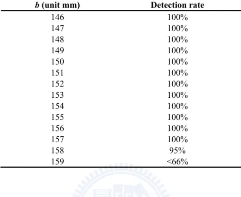
Table 2.1 Rates of successful detections of landmark shapes taken by cameras with
different shapes of hyperboloidal reflection mirror (c = 20mm)...41
Table 2.2 Error ratios in location estimations with landmarks located in the same directions but at different distance...41
Table 2.3 Errors in location estimations with the landmarks located in the same directions and at the same distances but with different camera heights...42
Table 3.1 Robot Location computation results for Case (4)...70
Table 3.2 Parameters involved or computed in extraction of projections in Fig. 10....70
Table 3.3 Robot location computation results for Case (1)...71
Table 4.1 Experimental result of stage-1 simulation...94
Table 4.2 Experimental result of stage-2 simulation...95
Table 4.3 Experimental result of stage-3 simulation...97
Table 5.1 Lateral car location estimation results...108
Table 5.2 Simulation results of estimating lateral car position using a fixed wheel radius value 20.75 cm...108
Table 6.1 A basic space-mapping table which records relations between coordinates of corresponding image points and real-world points...115
Table 6.2 Error ratios with camera looking downward at ceiling height 200cm...129
Table 6.3 Error ratios with camera looking downward at ceiling height 250cm...129
Table 6.4 Error ratios with camera looking downward at ceiling height 250cm...130
Table 6.5 Error ratios with camera at ceiling height 200cm for different tilted angle 90o (looking down), 70o, and 50o...131
xvii
Table 7.1 A pano-mapping table of size M×N...139 Table 7.2 A misalignment adjustment table of size M×N...146
xviii
List of Figures
Fig. 1.1 A catadioptric camera. (a) Structure of camera. (b) Acquired image...4 Fig. 1.2 Illustration of camera and reflective mirror type...5 Fig. 1.3 FOVs of different camera types [14]. (a) Dioptric camera. (b) Traditional
(perspective) camera. (c) Catadioptric camera...5 Fig. 1.4 An image acquired by a fish-eye camera...6 Fig. 1.5 Two-mirror omni-camera [15]. (a) Structure of camera. (b) Acquired image..6 Fig. 1.6 Omni-camera pairs. (a) Laterally paralell combinaiton. (b) Longitudinally
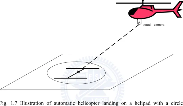
coaxial combinaiton...7 Fig. 1.7 Illustration of automatic helicopter landing on a helipad with a circled
H-shape...11 Fig. 1.8 Calibration objects used for mapping table construction. (a) A point pattern
used in Takeshita, et al. [59], laid on a floor. (b) A grid pattern used in Wang and Tsai [60], attached on a wall...13 Fig. 1.9 Example of unwarping an omni-image into a panoramic perspective image. (a)
Original omni-image. (b) Unwarping result of (a) which is a panoramic image...14 Fig. 1.10 Relations among proposed techniques in this study...16 Fig. 2.1 Relative positions of camera, ceiling, and circular landmark for providing
sufficient field of view and avoiding unexpected objects and humans
appearing in acquired images...20 Fig. 2:2 Coordinate systems involved in this study...23 Fig 2.3 Top view from the Z direction showing the relationship between new and
xix
obtained by rotating the u-axis through an angle of θw = tan−1(Yw/Xw) with
respect to the center of the circular-shaped landmark W...24 Fig. 2.4 Simulation of a series of circular shapes of the landmark at different places,
showing that the distorted landmark shape may be approximated well by ellipses. (a) illustration of the simulation results. (b) partially enlarged view of (a)...28 Fig. 2.5 Top view from the Z direction illustrating the relation between the axes of the
approximating ellipse and the horizontal distance of the circular-shaped landmark...30 Fig. 2.6 Illustration of the relative ALV location estimation. (a) and (b): the
displacement D of the vehicle. (c) and (d): the orientation of the vehicle...34 Fig. 2.7 Examples of successful detection of elliptical shapes. In (a)-(f), the elliptical
shapes of simulated landmark images are marked by white pixels. Black pixels are approximate ellipse points computed by the ellipse detection algorithm [17]. In (b)-(f), both horizontal and vertical grid lines are added in order to indicate the level of geometric distortion in each simulated image..36 Fig 2.8 All the experimental images were taken by an autonomous land vehicle
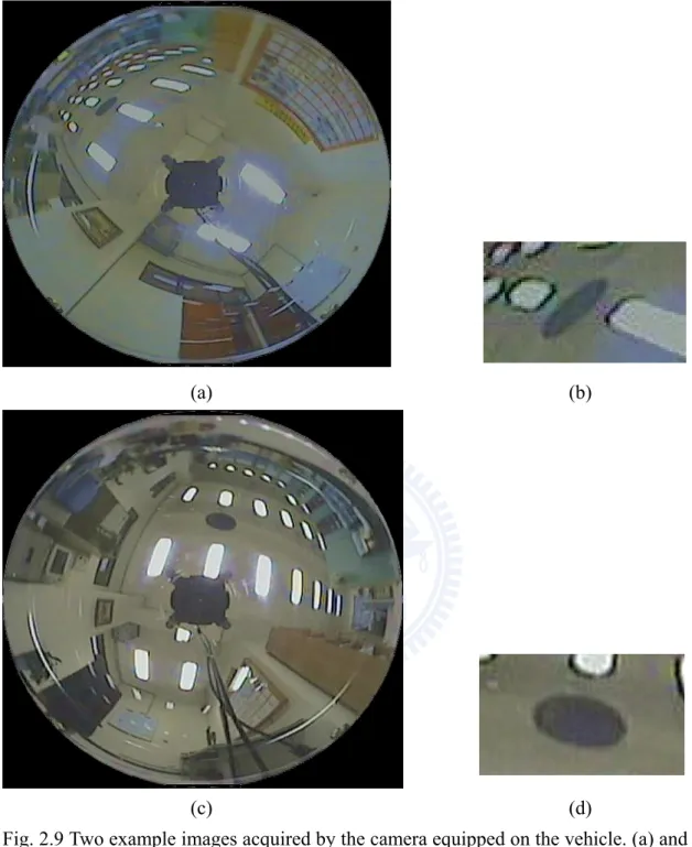
equipped with an upward-looking omni-camera. (a): the autonomous land vehicle. (b): a close look of the camera on the vehicle...37 Fig. 2.9 Two example images acquired by the camera equipped on the vehicle. (a) and (c): images acquired at different positions. (b) and (d): the enlarged images of the landmarks in (a) and (c), respectively...38 Fig. 2.10 Coloring scheme for identification of multiple circular shapes...40 Fig. 3.1 A house corner with a Y-shaped structure. (a) An omni-image of a corridor
ceiling with corners. (b) An image part of a corner. (c) Illustration of Y-shape of the corner...44
xx
Fig. 3.2 Six types of partial house corner structures. (a) A horizontal line with no endpoint. (b) A vertical line with no endpoint. (c) Two horizontal lines
intersecting at a point. (d) A horizontal line and a vertical one intersecting at a point. (e) A horizontal line with an endpoint. (f) A vertical line with an
endpoint...46 Fig. 3.3 Camera and image coordinate systems...50 Fig. 3.4 Illustration of a space line projected on to the image plane...51 Fig. 3.5 Case (1) a single horizontal line with no endpoint used for robot localization
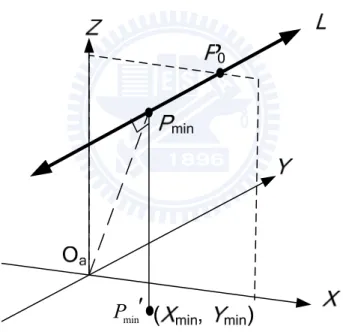
...57 Fig. 3.6 Finding minimum-distance point Pmin on horizontal line L for Case (1)...57 Fig. 3.7 A vertical line with no endpoint used in robot localization...61 Fig. 3.8.Two horizontal lines intersecting at a corner point used in robot localization
...63 Fig. 3.8 A horizontal line and a vertical one intersecting at a corner point used in robot localization...64 Fig. 3.9 A horizontal line with a corner point as an endpoint used in robot localization
...66 Fig. 3.10 A vertical line with a corner point as an endpoint used in robot localization
...68 Fig. 3.11 Extraction of horizontal and vertical lines by proposed Hough transform
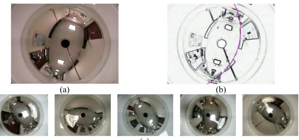
techniques for robot localization of Case (4). (a) An omni-image with a corner consisting of a horizontal line and a vertical one. (b) Extracted conic-section and radial-line projections shown as purple curves. (c) Five more images used in experiments...70 Fig. 3.12 Images used in experiment of robot localization of Case (1). (a) An image of
xxi
conic-section projection shown as purple curve. (c) Five more images used
in experiments...71
Fig. 4.1 Detail of a circled H-shape on a standard helipad...74
Fig. 4.2 An omni-image of a simulated helipad...75
Fig. 4.3 Top view of image plane and circular shape S illustrating side proportionality relation between approximating ellipse S′ and circular shape S...82
Fig. 4.4 Illustration of a space line projected onto the image plane...84
Fig. 4.5 Finding minimum-distance point Pmin on a boundary line L...86
Fig. 4.6 A view of a simulated helipad used in experiments of this study...92
Fig. 4.7 Four images of approaching stage of helicopter landing process. (a)-(d) Images 1-4...93
Fig. 4.8 Circular shape detection result of image 1...94
Fig. 4.9 Four images of aligning stage of helicopter landing process. (a)-(d) Images 5-8...94
Fig. 4.10 Circular shape and boundary line detection results of image 7. (a) Circular shape detection result. (b) Boundary line detection result...95
Fig. 4.11 Four images of docking stage of helicopter landing process. (a)-(d) Images 9-12...96
Fig. 4.12 Circular shape and boundary line detection results of image 11. (a) Circular shape detection result. (b) Boundary line detection result...97
Fig. 5.1 Relative coordinate systems. (a) Omni-camera and image coordinate systems. (b) Omni-camera and wheel coordinate systems...102
Fig. 5.2 Definition of corresponding image and space points...103
Fig. 5.3 A lateral car image with wheel shape detected as an elliptical shape...107
Fig. 6.1 Illustration of camera setup for space-mapping table construction in Stage 1 of proposed method...112
xxii
Fig. 6.2 Illustration of camera orientation change (with a tilt angle of θ)...113 Fig. 6.3 Illustration of quadrilateral extraction using a grid pattern on floor. (a) An
image of the grid pattern. (b) The lines approximating the grid lines...116 Fig. 6.4 Mapping of a pair of corresponding quadrilaterals in image and in calibration pattern...118 Fig. 6.5 Location estimation of a real-world point by inverse bilinear interpolation
...118 Fig. 6.6 Illustration of using side proportionality to compute coordinates of point P1
on a floor F1 with ceiling height H1...120
Fig. 6.7 Illustration of a tilted camera with angle with respect to the x -axis of the real-world coordinate system...122 Fig. 6.8 Lateral view (from the positive y-axis direction) of rotation result of floor
surface F1 in Fig. 6.7 through an angle of 90o − θ with P1 as the rotation pivot
point...122 Fig. 6.9 Illustration for verification of correctness of Eq. (6.11)...124 Fig. 6.10 Lateral view of Fig. 6.8 from direction of positive x-axis for verification of
correctness of Eq. (6.14)...125 Fig. 6.11 Fish-eye camera used in this study, which is attached to a rod fixed on
ceiling and can be tilted and moved up and down...126 Fig. 6.12 Images used for experiments reported here. (a) Taken with camera looking
downward at ceiling height of 200cm. (b) Taken with camera looking
downward at ceiling height of 250cm. (c) Taken with camera tilted for 50o at ceiling height of 200cm...128 Fig. 6.13 Effective field of view of camera measured by radius of an enclosing red
circle...128 Fig. 6.14 Illustrative images of applications of proposed location estimation method
xxiii
for autonomous vehicle guidance in an indoor environment (a laboratory where this study was conducted). (a) An image acquired by a
downward-looking camera affixed on ceiling. (b) A processed image in which autonomous vehicle center (white point) was detected for vehicle location estimation...132 Fig. 7.1 Alignment of catadioptric omni-camera. (a) Correct alignment. (b)
Axial-directional misalignment. (c) Lateral-directional misalignment...135 Fig. 7.2 Images of a color pattern acquired by a catadioptric omni-camera. (a) Image
taken with the camera correctly-aligned. (b) Image taken the camera
misaligned...135 Fig. 7.3 Omni-camera system...138 Fig. 7.4 Mapping between pano-mapping table and omni-image...139 Fig. 7.5 Lateral-view configuration for generating a panoramic image...141 Fig. 7.6 Configuration of an omni-camera wrapped with a calibration pattern. (a) A
calibration pattern wrapping transparent cylinder of camera. (b) Image of calibration pattern consisting of “fan-shaped” curved quadrilaterals...142 Fig. 7.7 Curved quadrilaterals forming a mutual corresponding pair...145 Fig. 7.8 Illustration of a curved quadrilateral with boundaries and interpolating curves segmented into equal-lengthed segments (a through d are all of equal lengths; e through h are similar, and so on)...147 Fig. 7.9 Illustrations of finding the central quadrilateral point M in a curved
quadrilateral...149 Fig. 7.10. Interpolating curve (blue) for two curve boundaries (red) found by a
quadratic classifier using coordinate data as patterns (the axes specify x- and
y-coordinates)...150
xxiv
corresponding curved quadrilateral...153 Fig. 7.12 Results of curved quadrilateral morphing by Algorithm 7.2 using simulated
data. (a) A simulated curved quadrilateral. (b) Result of 1st iteration. (c) Result of 2nd iteration. (d) Result of 3rd iteration...154 Fig. 7.13 Results of quadrilateral morphing for real data using Algorithm 7.2. (a) A
curved quadrilaterals. (b) Result of 1st iteration. (c) Result of 2nd iteration. (d) Result of 3rd iteration with intermediate curves removed...155 Fig. 7.14 Image unwarping results using Algorithm 7.1 and Algorithm 7.2. (a)
Reference image. (b) Working image. (c) Segmented calibration lines in (a) in thinned form. (d) Segmented calibration lines in (b) in thinned form. (e) Result of applying Algorithm 7.2 to (b) using the misalignment adjustment table. (f) A panoramic image generated form (e). (g) A panoramic image generated from...157 Fig. 7.15 Results of distorted image unwarping using Algorithm 7.2. (a) Distorted
omni-image. (b) Created panoramic image with correction by Algorithm 7.2. (c) Created panoramic image without misalignment correction...158
1
Chapter 1
Introduction
1.1 Motivation of Study
In the era of automation today, autonomous vehicles have been adopted in many application domains. Types of autonomous vehicles include mobile robot, land vehicle, computer-assisted car, helicopter, airplane, unmanned airborne vehicle, etc. In the study of autonomous vehicles, vehicle localization is indispensable in many applications, like navigation guidance, collision avoidance, automatic landing, driving assistance, etc. This problem is mentioned in the literature alternatively as robot
location, vehicle location estimation, object posture estimation, etc. A widely adopted
approach to vehicle localization is the vision-based technique, in which visual sensors like still and video cameras are used for environment sensing.
Most existing vision-based techniques deal only with frontal scenes acquired by traditional cameras and are easily interfered by unexpected objects around the vehicle. A feasible solution to this problem is to use an omni-directional camera (abbreviated as omni-camera in the sequel) [1][2][3][4][5][6][7] which looks at certain target shapes, usually called landmarks, attached on some objects in the environment. Uses of omni-cameras for solving this problem have the advantage of obtaining larger fields of view (FOVs) in the acquired omni-directional images (omni-images). Several factors should be considered in a solution of this kind, as discussed in the following. (1) Types of omni-cameras ---
With the advance of camera technology, many types of omni-camera have been proposed. A survey of them will be given later in this chapter. The larger variety of them in general provides more convenience and effectiveness for vehicle location
2
estimation. A systematic investigation of them is advantageous for improving the location estimation techniques.
(2) Types of landmarks ---
Many types of landmarks have been proposed in the past [1][6][10]. Although some specially-designed landmarks with good properties, like ease to extract from images of them, leading to analytic solutions, etc., have been proposed, they are not commonly seen in daily environments and need special arrangements which sometimes cause inconvenience. It is more desirable to use naturally-existing features in the environment, like straight lines, circles, rectangle, etc. The straight line might be the most commonly used landmark in the environment. It appears in indoor building structures such as baseboards, house corners, etc. Parameters from straight lines are widely studied for use in camera calibration. However, how to precisely and constantly acquire the parameters of lines is an important issue to solve. Circle is also a popular landmark shape. A circular-shaped landmark can be observed from any direction. Such rotational symmetry of the circle is a good landmark property, resulting in more precise and robust location.
(3) Locations of landmarks ---
Most landmarks proposed so far are located on the ground or attached on building walls, and so are apt to be occluded by people or objects around. An improper choice of the landmark location could lead to unreliable vehicle location estimation. On the contrary, a good landmark location will result in less landmark occlusion and image noise. Therefore, it is more convenient to use landmarks attached on the ceiling or affixed to other higher positions like house corners [8][9].
(4) Postures of omni-cameras ---
3
a work of omni-cameras calibration to obtain a set of camera parameters, followed by the use the parameters to compute the object location work [1][23][55][56][57][58]. However, the calibration process is sensitive to camera posture changes. To solve such a camera-posture sensitive problem, a commonly way is to abandon the original calibration results and reconstruct a new one in the new camera-environment configuration.
(5) Misalignment of omni-cameras ---
In real applications like vision-based autonomous vehicle navigation or security surveillance [13][46][65][66][67], a camera equipped on a vehicle might be shaken due to vehicle vibrations or one installed on a wall might be removed due to re-employment, causing possibly destruction of the camera structure and resulting in
camera misalignment, which causes displacements or/and re-orientations of the CCD
camera with respect to the reflective mirror of the omni-camera. A feasible solution is to unwarp a distorted omni-image taken by a misaligned omni-camera.
In this dissertation study, we investigate vehicle localization and related image analysis techniques for autonomous vehicle applications using new types of omni-cameras. We try to design methods to solve the related problems mentioned above, aiming at providing more effective techniques or algorithms for practical application uses.
1.2 Survey of Related Works
In this section, we survey works related to our study, including the categories of: (1) structures of various omni-cameras; (2) approaches to location estimation for different types of vehicle applications; and (3) image adaptation methods for adjusting
4
images taken by misaligned or posture-slanted cameras for the purpose of precise vehicle localization. These three categories of related works will be reviewed in Sections 1.2.1, 1.2.2, and 1.2.3, respectively.
1.2.1. Survey of Types of Omni-cameras
New types of omni-cameras can be categorized into the following categories: (1) catadioptric camera; (2) dioptric camera; (3) two-mirror catadioptric camera; and (4) omni-camera pair. More details about each category are described as follows.
(1) Catadioptric camera ---
A catadioptric omni-camera is a combination of a reflective mirror and a CCD camera as shown in Fig. 1.1(a). An image taken by such a kind of camera is shown in Fig. 1.1(b). With the aid of reflective surface from the mirror, a camera of this type can obtain larger FOVs in the acquired images. The lens of the CCD camera may be of a perspective or orthographic projection type, and the mirror surface of a catadioptric omni-camera may be in various shapes such as hyperbolic, circular, parabolic, or ellipsoidal, as illustrated in Fig. 1.2. With distinctive mirrors or lens, the images and calibration methods of the cameras are different in this category. Some works of vehicle location and image unwarping for this type of camera can be found in [1][2][3][4][5][6][7][8][9][10].
(a) (b)
5 orthographic paraboloid perspective hyperboloid spheroid perspective ellipsoidal perspective
Fig. 1.2 Illustration of camera and reflective mirror type.
(2) Dioptric camera ---
A dioptric omni-camera, looking like a traditional camera, has no reflective mirror, but with a “wider-angle” lens. It can capture incoming light rays from a wider FOV to form an omni-image. An illustration of such imaging difference from traditional and catadioptric cameras is shown in Fig. 1.3. The lens shape design of this group of cameras decides the formed images and their calibration methods. An example of this kind of omni-camera is the fish-eye camera. An image acquired by an fish-eye camera is shown in Fig. 1.4. Some works of vehicle location and image unwarping for fish-eye cameras can be found in [11][12][13].
(a) (b) (c)
Fig. 1.3 FOVs of different camera types [14]. (a) Dioptric camera. (b) Traditional (perspective) camera. (c) Catadioptric camera.
FOV FOV
6
Fig. 1.4 An image acquired by a fish-eye camera.
(3) Two-mirror catadioptric camera ---
Recently, the design trend of the catadioptric camera is to combine two reflective mirrors in a single camera. We call the resulting camera a two-mirror
omni-camera [15]. An example is shown in Fig. 1.5. The lights coming from a scene
point in the real world space are reflected by each mirror into the CCD camera, causing two corresponding image points in the resulting single image. Such image pairs form two “image belts” of the same scene with different scales.
(a) (b)
7 (4) Omni-camera pair ---
An omni-camera pair consists of two omni-cameras with different locations. An illustration is shown in Fig. 1.6, where two kinds of such camera pairs are seen. In theory, by using the corresponding pixels in the two images acquired from the cameras, stereo information can be derived stereo information. However, most research works in the past focus on omni-camera pairs with hyperbolic-shaped reflective mirrors [16]; works for pairs with other mirror shapes are yet to be completed.
(a) (b)
Fig. 1.6 Omni-camera pairs. (a) Laterally paralell combinaiton. (b) Longitudinally coaxial combinaiton.
1.2.2. Survey of Localization Methods for Different Vehicle
Applications
There are many appilications of autonomous vehicle localization techniques, such as: (1) indoor vehicle or robot guidance; (2) automatic helicopter landing; and (3) car driving assistance, etc. We review studies about these applications and related techniques in the following.
8 (1) Indoor vehicle or robot guidance ---
Indoor vehicle or robot guidance has been studied intensively in the past two decades. A frequently-adopted solution to this problem is to localize the vehicle or robot continuously in its navigation sessions, and guide its navigation path accordingly. The most commonly adopted vision-based approach aims to locate robots by analyzing images acquired with visual cameras [20][21][22]. Many kinds of techniques of this approach have been proposed, among which a popular one is the use of landmark images [1][23][24]. This kind of technique aims to compute the relative location of the vehicle or robot with respect to a landmark by analyzing the geometric hint exhibited by the landmark appearing in the acquired image. In such techniques, the location of the vehicle or robot is represented by both its position with respect to a reference point and its orientation with respect to a reference line included in the landmark, respectively, as we do in this study.
For indoor vision-based vehicle or robot localization, environmental structures abundant in buildings are often taken as landmarks. Among them, ceiling corners are the most commonly seen. They are good for vehicle localization because they are high and not easily occluded. In the past, there are few studies on house corners for robot localization [23][25], though there are related studies on using point and line features which compose the shapes of house corners [24][26]. For robot localization, Chou and Tsai [23] used a house corner which consists of three lines forming a shape of “Y”; Parlaktuna, et al. [25] used a range finder to detect the wall edges forming a house corner; Chen and Tsai [24] used lines on common object surfaces; and Park et al. [26] used scale-invariant feature points as visual landmarks. On the other hand, some studies on camera calibration, which is conceptually equivalent to the work of robot localization, focused on the investigation of using a sufficient number of
9
corresponding lines for solving camera parameters [28].
The previously-mentioned studies were mostly based on the use of traditional projective cameras. There are only a few studies on the use of omni-cameras for vehicle localization [1][29][31]. Most of them are based on using global environmental features and matching them against environmental maps to locate the robot. There are also related camera calibration works [32][33], which were conducted from the viewpoint of enhancing calibration precision, and, when applied to vehicle localization, are too complicated for real-time navigation applications.
Most vehicle localization using omni-images proposed up to now can be grouped into three types: triangulation, full-scene matching, and mirror-lens
projection, in accordance with the way of image information. In triangulation
techniques [1][2], a standard location method is to identify surrounding landmarks in the environment and find their corresponding locations in the environment map built in advance. By the measured bearings of the landmarks [1], the location of an autonomous vehicle can be obtained. Yagi [2] correlated the angle of the vertical edge in an omni-image to the environment map to acquire the location of the vehicle. However, sometimes it is difficult to find natural landmarks which can be identified stably from omni-images.
In full-scene matching techniques [3][4], a vehicle locates itself by comparing images taken at its current location with reference images stored in its memory. Full-scene matching provides better feasibility by the use of omni-cameras. However, it takes a lot of reference memory space to raise location precision. Gasper [3] showed that the position of the vehicle in the environment can be determined by comparing the vehicle’s current view with previously learned images, using a low-dimensional subspace of the input images obtained from a principal component analysis process.
10
Menegatti [4] simplified the location problem by using the Fourier components of omni-images as the signatures of the acquired views.
The unique mirror-lens projection relation of the omni-camera also can be used to derive the location of an autonomous vehicle by 3-D computer vision techniques [5][6]. In Koyasu [5], the range information, which is obtained by an omni-directional stereo vision system composed of a pair of vertically-aligned omni-cameras, helps not only creating a 3-D map but also locating the vehicle itself. In [6], Cauchois compared synthetic landmark images with real landmark images taken from a calibrated omni-camera to accomplish absolute vehicle location works. However, these methods might be unstable or inapplicable for locating a vehicle in a space crowded with people or full of objects, like in an exhibition room or in a library.
(2) Automatic helicopter landing ----
Many studies have been conducted for unmanned helicopter flying in the past [38][39][40][41][42][43][44][45]. Tsai and Yang [38] used parallel line information on a standard helipad as a hint for helicopter self-localization with respect to the circled H-shape on the helipad. See Fig. 1.7 for an illustration. The AVATAR project described in Saripalli, Montgomery, and Sukhatme [39] designed methods for landing a UAV in unstructured 3D environments using visual cues of the helipad described by moments. The work done by Shakernia, et al. [40] used point correspondence techniques to estimate the height and position of a UAV using multiple images. Garcia-Pardo et al. [41] presented techniques for locating circular landing areas using image processing operations like the contrast descriptor and correlation function. Mejias et al. [42] presented a vision-based feature tracking system for an autonomous helicopter, which estimates the position and velocity of window features in images and combines the result with GPS-positioning references to navigate the helicopter.
11
Tsai, Gibbens, and Stone [43] used the geometric properties of a standard landing mark of the T-shape to decide the vehicle position using single images. Yakimenko et al. [44] designed a method for shipboard landing of a UAV using infrared vision. Hespanha et al. [45] presented an integrated system to estimate the relative position and velocity of a UAV with respective to a ship using IR vision, inertial, and air data sensors.
Fig. 1.7 Illustration of automatic helicopter landing on a helipad with a circled H-shape.
All the above methods used the traditional projective camera for visual sensing, which has a fixed FOV, compared with that of the recently commonly-used
omni-camera. It is advantageous to use the omni-camera in automatic helicopter
landing to enlarge the viewing scope and consequently speed up the automatic landing process. In this direction, Hrabar and Sukhatme [46] designed an omni-vision system which tries to find the centroid of the H-shape on the helipad to generate appropriate commands for guiding the helicopter. Demonceaux, Vasserur, and Pegard [47] proposed a helicopter posture computation method using catadioptric omni-images of the horizon line to estimate the pitch and roll angles of the helicopter. Bazin et al. [48] extended the method of [47] to estimate further the yaw angle of the helicopter using
12
the information of vanishing points for automatic flight in urban areas. (3) Car driving assistance ---
Car driving assistance using traditional cameras has been studied intensively [50][51][52][53]. Recently, omni-cameras with wider views become popular. They are more suitable for car driving assistance because fewer cameras need be equipped. For example, Lai and Tsai [52] affixed a traditional camera on the right-frontal side of a
host car to take the image of a lateral car. To acquire a full frontal view, two more
traditional cameras should be used. Instead, one frontal omni-camera is sufficient. Additionally, car wheels are circular-shaped, providing geometric hints for lateral car localization [52]. However, when a circle appears in an omni-image, it becomes irregular in shape and cannot be described mathematically [54], leading to difficulty of extending the existing vehicle localization methods for omni-images. This problem has been solved in this study.
1.2.3. Survey of Image Adaptation Methods for Adjusting Images
Taken by Misaligned or Posture-Slanted Cameras
Variou image adaptation methods for adjusting images taken by non-standardly-postured cameras, including: (1) adaptation to camera posture changes and (2) adjustment for misaligned omni-cameras, are surveyed as follows.
(1) Image adaptation to camera posture changes ---
A conventional solution to the object location estimation problem, which a
reverse of the vehicle localization problem in concept, is to conduct a work of camera
calibration to obtain a set of camera parameters, followed by the use of the parameters to compute the object location [1][23][55][56][57][58]. Camera calibration methods often use specially landmarks or environment features to derive formulas or algorithms to compute camera parameters. The computation process is in general
13
complicated and time-consuming. The camera used in such methods is usually mounted on a robot or vehicle and so is mobile, while the landmark or feature used by the methods is usually fixed in the environment.
An alternative solution to the object location estimation problem is to use a
space-mapping approach [36][59][60][61] which transforms the image space into the
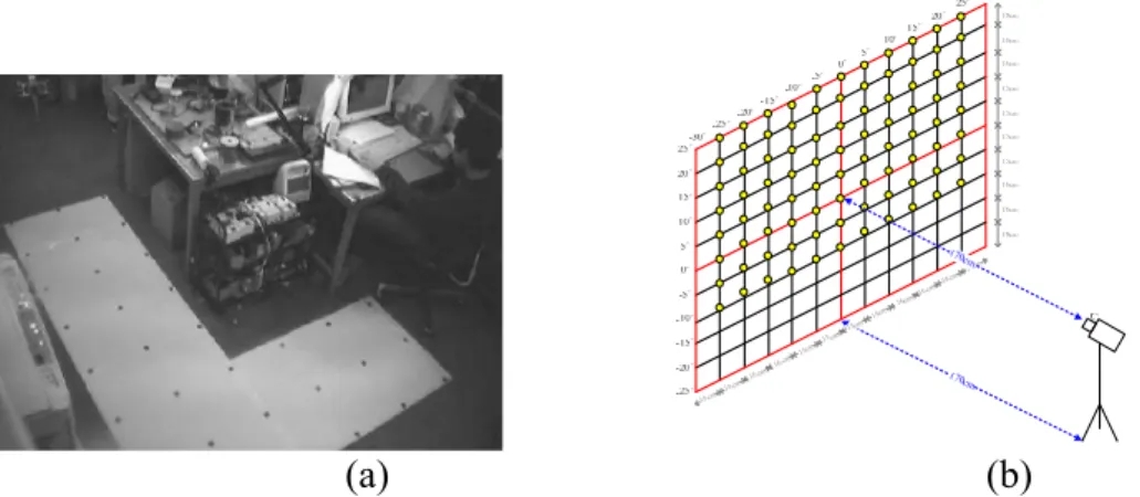
real-world space according to a space-mapping table. That is, the coordinates of an object point in an acquired image is mapped to the corresponding real-world coordinates of the point by a table lookup scheme. Thus, the above-mentioned camera calibration process is avoided, and the approach may be said to conduct direct object location estimation. The space-mapping table is constructed in advance, usually with the aid of a certain calibration pattern, before the camera is deployed in an application environment. Two examples of calibration patterns used in [59][60] are shown in Fig. 1.8, where a point pattern laid on the floor with a camera affixed on a ceiling was used in Takeshita, Tomizawa, and Ohya [59], and a grad pattern attached on a wall with the camera mounted on an autonomous vehicle was used in Wang and Tsai [60].
(a) (b)
Fig. 1.8 Calibration objects used for mapping table construction. (a) A point pattern used in Takeshita, et al. [59], laid on a floor. (b) A grid pattern used in Wang and Tsai [60], attached on a wall.
14
Omni-camera misalignment occurs, for example, when the optical axis of the perspective camera of an omni-camera system are not coincident with the mirror axis which is perpendicular to the mirror base and through the mirror base center. Camera misalignment causes conventional image unwarping methods for image rectification inapplicable because of the resulting changes of the camera parameters. For an example of convenctional image unwarping, see Fig. 1.9. To solve this problem, Jeng and Tsai [71] proposed an omni-image unwarping method for dealing with the axial-directional camera misalignment problem. On the other hand, there are very few studies on image unwarping for lateral-directional camera misalignment so far except Mashita, Iwai, and Yachida [34] in which camera calibration is conducted first before image unwarping is carried out. In this study, we propose another method which is more convenient to apply and yields more accurate results.
(a) (b)
Fig. 1.9 Example of unwarping an omni-image into a panoramic perspective image. (a) Original omni-image. (b) Unwarping result of (a) which is a panoramic image.
1.3 Contributions of This Study
The major contributions of this study include proposing of the following techniques:
15
(1) A new method for proving and approximating circular shape images acquired by hyperboloidal omni-cameras as ellipses is proposed.
(2) A novel method for describing the projection of a space line on the omni-image plane as a conic-section and extracting it by a low-dimensional Hough transform is derived.
(3) A new localization method for indoor autonomous vehicle guidance using omni-images of circular landmarks on ceilings is proposed.
(4) A systematic investigation of possible indoor corner structures for applications of vehicle localization is conducted and relevant image analysis techniques are proposed.
(5) Analytic formulas for vehicle localization using single-view images of all possible house corner structures are derived for fast computation and real-time indoor vehicle guidance.
(6) A novel omni-vision based self-localization method for automatic helicopter landing on standard helipads is proposed.
(7) A new method for localization of lateral vehicles for car driving assistance using omni-images is proposed.
(8) A new approach to adaptation of existing space-mapping methods for object localization to camera setup changes is proposed.
(9) An unwarping method for images taken by misaligned omni-cameras without camera calibration by curved quadrilateral morphing using quadratic pattern classifiers is proposed.
An illustration of the relations of the above-mentioned techniques is shown in Fig 1.10 where each technique is categorized into three groups: image adjustment, new feature analysis, and new localization techniques and applications, colored by three different blocks. Moreover, the mutual relations among the techniques are
16
annotated by arrows. That is, between two neighboring techniques, the direction of the arrow means that the previous technique can be applied to the following one.
Fig. 1.10 Relations among the proposed techniques in this study.
1.4 Dissertation Organization
In the remainder of this thesis, we describe the proposed methods for various applications in the chapters, respectively. In Chapter 2, we propose a method for location estimation for indoor autonomous vehicle navigation by omni-directional vision using circular landmarks on ceilings. In Chapter 3, we propose a systematic approach to indoor vision-based robot localization using corner features in omni- images. In Chapter 4, we propose an omni-vision based self-localization method for
17
automatic helicopter landing on standard helipads. In Chapter 5, we propose a method for omni-vision based localization of lateral vehicles for car driving assistance. In Chapter 6, we propose a technique for adaptation of space-mapping methods for object location estimation to camera setup changes. In Chapter 7, we propose a method for unwarping of images taken by misaligned omni-cameras without camera calibration by curved quadrilateral morphing using quadratic pattern classifiers. In each chapter, we describe relevant techniques and applications of the proposed methods, and include experimental results to show the feasibility of the methods. Discussions and suggestions for future studies are also included.
18
Chapter 2
Location Estimation for Indoor
Autonomous Vehicle Guidance by
Omni-vision Using Circular Landmarks on
Ceilings
2.1 Idea of Proposed Method
Vehicle localization is essential for guidance of autonomous vehicles in many indoor navigation applications. Most existing vision-based techniques deal only with frontal scenes acquired by traditional cameras and are easily interfered by unexpected objects around the vehicle. A feasible solution to this problem is to use an omni-camera which looks upward at certain landmarks attached on the ceiling [7]. This solution has the unique advantage of providing wide-angle views with fewer objects appearing in the FOV, thus reducing the guidance error coming from landmark occlusion, noise inference, etc. This is important for applications of intelligence robots such as cleaning robots, pet robots, tour guide robots, etc., which must work among humans or objects at close distances. On the other hand, even though obtaining the distance and orientation of the circular landmarks on the ceiling can be easily realized with a traditional perspective camera [8][9], a well-designed single omni-camera system may be used to replace several standard cameras so far as the image taking range is concerned.
In this study, a location estimation method for indoor autonomous vehicle guidance using omni-images of circular landmarks on ceilings is proposed. Analysis of circular shapes in omni-images is not well studied so far. It is found in this study
19
that a circular shape, which becomes an irregular shape in an omni-image with no known shape descriptor, can be well approximated analytically by an elliptical shape. Consequently, it is appropriate to guide a vehicle equipped with an upward-looking omni-camera using a circular shape attached on a ceiling as a landmark, as is done in this study. Several merits can be identified in this approach, including: (1) the circular-shaped landmark attached on the ceiling is identically observable from every direction; (2) the circular shape, being elliptical when imaged, is easier to detect in low-resolution omni-images; (3) the elliptical shape provides more precise parameters for location estimation; (4) the elliptical shape does not get mixed up easily with other shapes found in the environment. Owing to these merits, stable and precise relative vehicle location estimation can be achieved for navigation. An illustration of the experimental navigation environment for this study, including a vehicle, a ceiling, and a landmark, is shown in Fig. 2.1.
In the proposed method, at first an upward-looking omni-camera on a vehicle is used to take an image of a circular-shaped landmark attached on the ceiling of an indoor space. An ellipse detection algorithm [17] is applied next to detect the projected shape of the landmark in the image. The irregular shape formed from the circular shape in the omni-image is approximated by an elliptical shape. The location of the landmark, including its distance and orientation, with respect to the camera on the vehicle are then derived analytically in terms of the major axis length and the center coordinates of the approximating ellipse. Finally, the move distance and the orientation change of the vehicle between two consecutive observations of the landmark are derived, which are useful for a number of autonomous vehicle applications.
The remainder of this chapter is organized as follows. In Section 2.2, we derive the analytic equations for approximating as an elliptical shape the irregular shape in
20
an omni-image taken of a circular-shaped landmark. In Section 2.3, we describe how we estimate the vehicle location from the acquired image using the derived analytic equation, and show an application of the results to autonomous vehicle guidance. In Section 2.4, some experimental results are described to show the precision and feasibility of the proposed method. Finally, some conclusions are given in Section 2.5.
2.2 Approximation of Irregular Shape in Omni-image
Taken of Circular-shaped Landmark by Ellipse
The circular shape attached on the ceiling of the vehicle navigation environment for use as a landmark becomes irregular with no mathematical shape descriptor in an omni-image taken with a hyperboloidal omni-camera. We can approximate the Fig. 2.1 Relative positions of camera, ceiling, and circular landmark for providing
sufficient field of view and avoiding unexpected objects and humans appearing in acquired images.
Camera 1.0m~6.5m
Ceiling Circular
21
irregular shape well by an ellipse, as mentioned previously, and this fact will be proved here. Specifically, an equation of the approximating elliptical shape in the image will be derived. The validity of this ellipse approximation will become clear in the derivation. The precision of the approximation will also be proved by some experimental results.
In Section 2.2.1, the projection transformation between the camera coordinate system and the image coordinate system will be described first. Then, the coordinate systems will be rotated horizontally to derive the equation of an ellipse in the image. In Section 2.2.2 a simulated shape of the circular landmark computed with the derived equation will be compared with the shape obtained by an imaging projection based on [5] to show the effectiveness of the proposed elliptical shape approximation.
2.2.1. Approximation of Distorted Circular Shapes in Omni-images
by Ellipses
The camera and image coordinate systems involved in this study using a hyperboloidal omni-camera are depicted in Fig. 2.2, with their coordinates specified by (X, Y, Z), and (u, v), respectively. The hyperbolic shape of the omni-directional mirror in the camera coordinate system may be describedas:
1 2 2 2 2 − = − b Z a R , R= X2 +Y2 . (2.1)
The focal point OM of the mirror is located at (0, 0, −c) and the camera center OC at (0, 0, +c), in the camera coordinate system, where c= a2+b2 . The projection
relationship between the image coordinates (u, v) and the camera coordinates (X, Y, Z) can be described as follows [5][34][35][36]:
22 2 2 2 2 2 2 2 ( ) ( )(Z ) 2 (Z ) Xf b c u b c c bc c X Y − = + − − − + + , 2 2 2 2 2 2 2 ( ) ( )(Z ) 2 (Z ) Yf b c v b c c bc c X Y − = + − − − + + , (2.2)
where f is the focal length of the camera.
In Fig. 2.2, let the circular-shaped landmark and its center and radius be denoted by W, Pw and Rw, respectively. And let the image of W in the hyperboloidal image be denoted by Q. Also, let (Xw, Yw, Zw) denote the camera coordinates of Pw. In this study, the normal vector of the landmark is assumed to be parallel to the optical axis of the camera. To simplify the derivation described later, we rotate, as shown in Fig. 2.3, horizontally the camera coordinate system and the image coordinate system through an angle of θw defined by:
1 - w w w Y tan X θ = . (2.3)
Then, the relation between the original camera coordinates (X, Y, Z) and the resulting
ones (X′, Y′, Z′) may be described by:
X′ = Xcosθw + Ysinθw, Y′ = Ycosθw − Xsinθw, Z′ = Z (2.4) and the relation between the original image coordinates (u, v) and the resulting ones
(u′, v′) may be described by:
u′ = ucosθw + vsinθw, v′ = usinθw− vcosθw. (2.5) Also, after this rotation, the circular shape of W in the new camera coordinate system
may be expressed by:
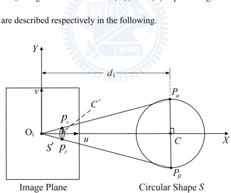
23 OM Oc Zw X Y Z u v Focal Point Camera Center Image Plane Camera Coordinate origin Ceiling Hyperbolical Mirror Circular Landmark W
Fig. 2:2 Coordinate systems involved in this study. (X′ − Xw′)2 + (Y′ − Yw′)2 = Rw2, Z′ = Zw′,
given that the center point Pw of W is located at (Xw′, Yw′, Zw′) with Xw′ = Xwcosθw +
Ywsinθw, Yw′ = Xwsinθw − Ywcosθw, Zw′ = Zw according to (2.4). Notice that Yw′ is now zero after the rotation according to Fig. 2.3, so that the above equation becomes
(X′ − Xw′)2 + Y′2 = Rw2, Z′ = Zw′. (2.6) Also, by the optical geometry of the camera described by (2.2), we have
Z' Y' = u' v' , (2.7) or equivalently,
24 Y' X' u' = ' v . (2.8)
Eq. (2.8) will be used in Section 2.3.1 later.
We are now ready to prove the previously-mentioned fact that the irregular shape of the circular landmark W appearing in the omni-image may be well
approximated by an ellipse. After horizontally rotating the camera and the image coordinate systems for the angle of θw = tan−1(Yw/Xw) described by Eq. (2.3), Eq. (2.2) becomes 2 2 2 2 2 2 2 ( ) ( )(Z ) 2 (Z ) X ' f b c u' b c ' c bc ' c X ' Y ' − = + − − − + + 2 2 ( ) 2 2 2 2 2 ( )(Z ) 2 (Z ) Y ' f b c v' b c ' c bc ' c X ' Y ' − = + − − − + + . (2.2A) Fig 2.3 Top view from the Z direction showing the relationship between new and
original coordinate system with the new image coordinate system (u′, v′)
obtained by rotating the u-axis through an angle of θw = tan−1(Yw/Xw) with respect to the center of the circular-shaped landmark W.
25
In addition, the new Y-coordinates Yw' of the landmark circle center is 0. Then, by assuming that the horizontal distance from the origin of the camera coordinate system to the landmark is much larger than the radius of the landmark, we have Y' << X' and the circle (X' − Xw')2 + (Y' − Yw')2 = Rw2 with Yw' = 0 may be regarded relatively as a point which is its center located at (Xw', Yw') so that X'2 + Y'2 ≈ Xw'2 + Yw'2 = Xw'2. Also, Z' is a constant (denoted as hw now) because the ceiling on which the landmark is attached is assume to be parallel to the camera coordinate system. As a consequence, the second Eq. in (2.2A) above for v' can be simplified to
2 2 ( ) 2 2 2 2 ( )(Z ) 2 (Z ) Y ' f b c v' b c c bc c x 'w − = + − − − + or equivalently, Y' = v'M (2.9) where M is 2 2 ( ) 2 2 2 2 ( )(Z ) 2 (Z ) f b c M b c c bc c X 'w − = + − − − + .
The other coordinate u′ of each shape pixel of the landmark W may also be derived by approximation, but in a different way. Under the same assumption mentioned above that the radius of the landmark is relatively very small with respect to the horizontal distance from the origin of the camera coordinate system to the landmark, the magnitude of X′ of each shape pixel of the circular landmark W in the
camera coordinate system is much larger than that of Y′. Therefore, we may neglect
the influence of the magnitude of Y′ in the computation of u′ described by the first
26 2 2 2 2 2 2 ( ) ( )(Z ) 2 (Z ) X ' f b c u' b c c bc c X ' − = + − − − +
and compute u' just in terms of X'. Regarding the above equation in the form u' = F(X′), we may use the Taylor series to expand the function around Xw' as
u' = F(X′) = F(Xw′) + [(X′ − Xw′)/1!]F'(Xw′) + [(X′ − Xw′)2/2!]F''(Xw′) + …. Ignoring the terms after the second, we have
u' ≈ F(Xw′) + [(X′ − Xw′)/1!]F'(Xw′) = uw' + (X′ − Xw′)F'(Xw′). (2.10) Eq. (2.10) may be transformed easily into
X′ ≈ Xw′ + (u′ − uw′)/F'(Xw′) (2.11)
with the first derivative F' calculated to be:
F'(Xw′) = E( 1 2 E w ) E E E w C X ' A B − B D +X ' , (2.12) where 2 2 ( ) E A = f b −c , 2 2 2 ( )( ) E w B = b +c z c− −C D X '+ , 2 E C = bc, 2 ( ) E D = z c− w Z =h .
Now with X' and Y' available, we come to the final stage of the derivation of the
equation of the ellipse for approximating the distorted circular shape of the landmark in the omni-image. By substituting Eqs. (2.9) and (2.11) into Eq. (2.6) and rearranging the result, we can get
27
( )
2 2 2 2 2 2 ( ) 1 w w w w u' u ' v' M R R F' X ' − + = (2.13)which obviously specifies exactly an elliptical shape centered at (uw′, 0) with the lengths of the major and minor axes being RwF'(Xw′) and Rw/M, respectively. This completes the proof.
2.2.2. Effectiveness of Shape Approximation
To check the effectiveness of the approximation of the circular shape of the landmark by the elliptical shape using Eq. (2.13), we show in Fig. 2.4 an example of the simulation results obtained in this study, in which both the original circular shape and the approximating elliptical one are drawn and superimposed on each other for comparison: the former shape being drawn by Eq. (2.6) and then projected into the image plane by Eq. (2.2), and the latter being drawn directly by Eq. (2.13).The outer big circle in the figure marks the field of view of the camera. Inside the big circle, the original distorted circular shapes of W at different positions are drawn with white
pixels, and the approximate elliptical shapes are computed using the coordinates of the white pixels and drawn by black pixels.
From the figure, we can see that each black ellipse overlaps the corresponding white distorted circle quite well. This shows that the distorted circular shape of the landmark in the omni-image indeed may be approximated by the ellipse described by Eq. (2.13). This discovery offers great helps, as found in this study, in utilizing this kind of circular landmark to provide the location information for vehicle guidance, as described in the following section.