sion efficiency to pass the power from a local oscillator (LO) to an antenna without wasting received power at the oscillator port. A quadrature Doppler radar system is also implemented with the proposed quadrature hybrid mixer and defected-ground-structure LO. Compared to a conventional quadrature radar, the received power of the proposed architecture is enhanced by 3.3 dB when the LO power is 10 dBm, and is enhanced by 16.2 dB when the LO power is reduced to 0 dBm. Additionally, the improvement in received power is attributed to the improved transmission and lower receiving loss than that of the conventional ones. Capable of determining speeds lower than 0.05 km/h, which corresponds to a 1-Hz Doppler shift. The proposed Doppler radar architecture can identify the direction of the displacement due to use of the quadrature technique.
Index Terms—Doppler radar, quadrature mixer, quadrature radar, velocity measurement.
I. INTRODUCTION
M
ICROWAVE radar technology has attracted many at-tentions in many applications such as speed detection, collision avoidance, traffic control and management, and health care, as well as motion detectors [1]. These radar applications highly prioritize a high-performance compact-size simple struc-ture, and low-cost [2].Among current radar technologies, continuous wave (CW) radars have a relatively simple circuit structure, thus ensuring compactness and inexpensive solutions [3]. This kind of radar has found many applications in the automotive field such as speed sensors and traffic control systems [4]. Of these systems, transmitting power is generated and the receiver is driven simultaneously using a single local oscillator (LO). LO power usage efficiency reflects the efficiency of the radar front-end in using the LO power in transmission and receiving approaches.
Manuscript received January 29, 2009; revised August 29, 2009. First pub-lished November 24, 2009; current version pubpub-lished January 13, 2010. This work was supported in part by the National Science Council, Taiwan, under Contract NSC 97-2221-E-009-041-MY3.
The authors are with the Department of Communication Engineering, National Chiao Tung University, Hsinchu, Taiwan 30050 (e-mail: danise. [email protected]; [email protected]).
Color versions of one or more of the figures in this paper are available online at http://ieeexplore.ieee.org.
Digital Object Identifier 10.1109/TMTT.2009.2035874
efficiency is crucial to improving the sensitivity. A higher LO power usage efficiency implies a higher signal strength that can be acquired from the sensor with the same LO power injected into the radar front-end. Systems with two antennas are likely to have the optimum local power usage efficiency, regardless of the transmission loss incurred in the power distribution network [5], [6]. However, the system size is twice that of a system with a single antenna. Radar with a single antenna is typically implemented with either a circulator or a coupler following the antenna. Circulator components are normally prohibitively expensive; meanwhile, in the coupler architecture, half of the receiving power is dissipated at the LO port. Additionally, half of the transmission power is expended to drive the mixer. This paper presents a novel hybrid type mixer to increase the power usage efficiency of the LO. Placed in a series between the LO and antenna, the proposed hybrid mixer passes LO power through and down converts the radar signal. Additionally, the proposed hybrid mixer requires lower than half the LO power than the conventional one to drive the mixer and wastes no received power in the architecture.
The quadrature radars can detect the speed and direction of a target and it can also measure the displacement of static environment [7], [8]. Even human vital signals are detected very well with quadrature mixing technology [9], [10], owing to its ability to extract Doppler signal with a significant higher signal-to-noise ratio [11]. The quadrature radar architecture reported in [12] applied a coupler to isolate the transmitter and receiver paths. Another approach [13] adopted a balanced coupler network to reduce the transmitter-to-receiver leakage. However, these approaches have a low power usage efficiency, as evidenced by termination of the reflected LO powers from the mixers at a resistor and dissipation of half of the receiving power at the LO port.
This paper presents a new quadrature mixer architecture con-figured by hybrid mixers, with an application in a 10.5-GHz quadrature radar. The proposed quadrature radar architecture can reduce the transmission power loss and has no power loss in the distribution network during receiving. The phase noise of the LO affects the resolution of a Doppler radar [14]. An LO designed with the defected ground structure (DGS), which possesses a low phase noise, is applied as the signal source in this radar. A quadrature radar with a conventional quadrature mixer is also implemented for comparison. The remainder of
Fig. 1. Block diagram of: (a) conventional quadrature radar with branch-line coupler and quadrature mixer, (b) proposed radar with quadrature hybrid mixer implemented of hybrid mixers, and 45 delay lines.
this paper is organized as follows. Section II presents the con-figuration of the proposed quadrature mixer architecture and in-troduces its operation principles. Section III then illustrates the design and measurement results of the DGS frequency synthe-sizer. Section IV then shows the fabrication and experimental results of the 10.5-GHz quadrature Doppler radar. Conclusions are finally drawn in Section V.
II. PRINCIPLE OF THE QUADRATURERADAR
WITHHYBRIDMIXER
Fig. 1(a) and (b) schematically depicts the quadrature radar transceivers with conventional mixers and with the proposed quadrature hybrid mixer, respectively. The conventional radar architecture consists of an antenna, an LO source, two branch-line couplers, a two-way power divider, and two mixers along with two low-pass filters (LPFs). In this architecture, the first branch-line coupler is used to separate the transmitting and re-ceiving signals, while the other coupler is used to generate two LO signals with 90 phase difference for quadrature mixing. Half power of the output signal from the signal source is trans-ferred to the antenna through the first branch-line coupler and radiated through the antenna. The radiated signal is reflected from the object and captured by the same antenna. The received signal is then coupled to the mixer by the first branch-line cou-pler and down converted into the baseband by the two mixers. Finally, unwanted signals such as higher order harmonic signals are filtered via LPF.
The conventional architecture, as shown in Fig. 1(a), incurs a significant power loss because despite the transmission loss contributed by the transmission lines and path loss from the an-tenna to the object, 6-dB power loss is always contributed by the first branch-line coupler in theory. In the first branch-line
Fig. 2. Schematic of the quadrature hybrid mixer, which consists of two hybrid mixers along with two 90 branch-line couplers and baseband amplifiers.
coupler, half of the LO power is used to drive the mixer, while half of the received power is terminated at the LO port. The pro-posed architecture in Fig. 1(b) does not suffer from this problem. During transmission, the LO power is equally divided by the first branch-line coupler and inserted into the hybrid mixers. The hybrid mixer takes the necessary energy required to drive the mixing diodes only and, then, passes the remnant power through the mixer. Eventually, the remaining powers from the two hybrid mixers are combined by the second branch-line coupler and in-serted into the antenna. During receiving, the second branch-line coupler divides the received power equally with 90 phase dif-ference and placed into the mixers. Theoretically, this architec-ture has 6-dB enhancement of overall performance in an ideal case. In practice, a certain amount of LO power injected into the hybrid mixer is taken to drive the mixer diodes. The power taken to drive the mixer diodes is typically lower than half of the total LO power. Therefore, the overall LO power are efficiently used in this architecture. Notably, two 45 delay lines are placed indi-vidually in the upper and lower paths to produce I/Q IF signals. Fig. 2 schematically depicts the proposed quadrature hybrid mixer, which consists of two hybrid mixers and two attached 90 branch-line couplers. Each hybrid mixer consists of a 90 branch-line coupler, two Schottky diodes, and is followed by two LPFs. Let the signal from the LO be expressed as
(1) where is the amplitude of the LO signal and denotes the LO frequency (which is also the frequency of the transmitting signal). After passing the first branch-line coupler and the 45 delay line, the signal entering the upper hybrid mixer (mixer I) can be expressed as
Meanwhile, the LO signal also enters the lower hybrid mixer (mixer II), resulting in a signal from mixer II as
(6) This signal, after passing the 45 delay line, enters the second branch-line coupler and combines with the signal from mixer I at the output port, i.e., the antenna port. The total transmitting signal at the antenna port can thus be obtained as follows:
(7) It is seen that the insertion loss of the signal from the LO to the antenna comes from the reflection loss at the Schottky diodes.
In the receiving path, the signal reflected from the object is given by
(8) where and are the amplitude and frequency of the signal received by the antenna, respectively. After passing the second branch-line coupler and the branch line in mixer I, the received signals at diodes and are given by
(9) (10) These signals mix with the LO signals (3) and (4), respectively, leading to the fundamental terms of the harmonics at the LPF output ports
(11)
(12) where is the conversion coefficient of the mixer diode, or represents the mixer conversion loss. The output at each IF port of the hybrid mixer is just out of phase, a low-noise dif-ferential amplifier with gain of is then used here to transfer
Fig. 3. Measured and simulated conversion loss of the quadrature hybrid mixer and the insertion loss from LO to antenna without biasing.
the differential signal into single-ended output. The differential amplifier can also help to reject the common-mode noise, which helps to improve the receiver sensitivity [15]. After this ampli-fier, the received IF signal at the in-phase (I) port has the fol-lowing form:
(13) Similarly, the IF signal at the quadrature (Q) phase port ( port) can be derived as
(14) Apparently, the IF outputs at both I and Q ports of the mixer are equal amplitude and 90 difference in phase.
To demonstrate the above theory, a 10.5-GHz quadrature hy-brid mixer was implemented. Both the branch-line couplers and delay lines are designed using the 2.5-D electromagnetic (EM) simulator of IE3D [16]. The active circuit simulation and de-sign are performed using MWOffice [17]. The quadrature hy-brid mixer was fabricated on an RO4003 substrate, which has a dielectric constant of 3.38 and thickness of 20 mil. The mixer diode is selected using MA4E2054.
Fig. 3 illustrates the simulated and measured frequency re-sponses of the proposed quadrature hybrid mixer without bi-asing. The insertion loss from the LO to antenna, including the reflection loss from the diode and the overall circuit losses, and the conversion loss of the quadrature hy-brid mixer are presented. This experiment is based on an LO power of 10 dBm. By considering that the nonlinear character-istic should generate many harmonic signals, the experimental results were assessed by a spectrum analyzer. Around the op-erating point at 10.5 GHz, the mixer shows a conversion loss of 15.5 dB from RF to the I channel, insertion loss of 3.1 dB from the signal source to the antenna, and return loss better than 15 dB, which covers the range from 9.8 to 11.2 GHz. Conse-quently, the mixer takes approximately half of the transmitting power to drive the mixer diodes and leave the remaining half power to the antenna. The differences between the simulated and measured ones are caused by the variety of each diode. This
Fig. 4. Simulated return losses of: (a) a single LO signal and (b) both LO and RF signals injected into a single diode section.
unbalanced characteristic deteriorates the mixer performance slightly in both conversion and insertion losses.
According to the measurement results in Fig. 3, it seems that most of the LO power is reflected by the diode. Fig. 4(a) de-scribes the simulation of the return loss in a single diode section. According to this figure, most input power is reflected when the power is lower than 13 dBm. When the power exceeds 13 dBm, the return loss becomes high, thus limiting the output power. The nonlinear circuit simulator allows us to determine the indi-vidual return losses of a two-tone signal. Fig. 4(b) summarizes the simulation results when both the LO and RF are injected into the diode with a relative frequency shift of 1 MHz. The LO is excited at a power level of 10 dBm, while the RF is considered as the small signal. This finding shows different return losses of each signal. Most of the LO signal is reflected in the design frequency, while more than half of the RF signal is absorbed by the diode.
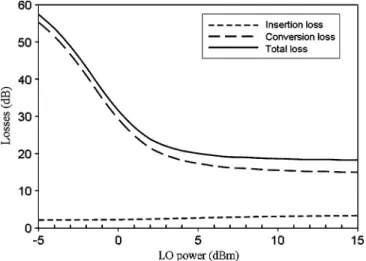
In some applications, the radar is considered to operate under low LO power, requiring consideration of the LO power level. Fig. 5 summarizes those results, where the insertion loss, con-version loss, and total loss are functions of the LO power level. No bias is applied to the mixer. This figure indicates that the
Fig. 5. Measured performance of the quadrature hybrid mixer without a bias versus LO power level.
Fig. 6. Quadrature hybrid mixer performance versus dc bias with LO power equal to 0 dBm.
conversion loss for LO power lower than 0 dBm is extremely high. As the power increases, the conversion loss decreases, and finally saturates at 15 dB when the LO power is higher than 10 dBm. Meanwhile, the insertion loss has only a slight incre-ment when the LO power increases. In the proposed architec-ture, the LO signal leakage to the RF port is used as the inter-rogating signal of the radar. Therefore, another parameter, i.e., the total loss, which is defined as the summation of the con-version loss and insertion loss, is illustrated for considering the power usage efficiency of the local source. The total loss almost saturates at 18.2 dB when the LO exceeds 10 dBm. This mixer adopts an extra dc bias [18] to enhance the low LO power per-formance. Bias on the mixer diode can help to lower the bar-rier voltage, thus enhancing the low power performance. The four diodes within the quadrature hybrid mixer are placed in parallel, explaining why they can be easily biased when using only a single bias voltage. Fig. 6 shows the biased results versus the bias voltage when the LO power is 0 dBm. According to this figure, the insertion loss changes only slightly, while the conver-sion loss comes to the lowest when the bias voltage is near 0.7 V, thereafter it increases higher when the bias voltage is more than
1 V. Consequently an optimized total loss can be obtained when the bias is 0.7 V. Table I summarizes of the optimized operating point for various LO power levels.
III. DESIGN AND MEASUREMENT OF THE
DGS FREQUENCYSYNTHESIZER
In the radar application, an LO source with acceptable phase noise is vital to the radar performance. A frequency synthesizer can easily achieve a stable output frequency and satisfactory phase noise with adjustable frequency using a simple schematic and reasonable cost. In this study, the LO signal is provided by a 5.25-GHz frequency synthesizer followed by a frequency doubler, where the synthesizer is designed with a two-section DGS for reducing the phase-noise level.
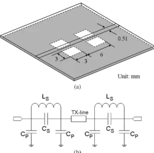
The DGS is an etched area in the backside ground of a mi-crostrip line. The disturbance on the ground plane can change characteristics of a transmission line such as line capacitance and inductance. The DGS structure provides a bandgap char-acteristic in the design frequency with only one unit lattice, resulting in an improved quality factor than other microstrip planar structures [19]. The DGS has found many applications in the filter and has also been proven to reduce the oscillator phase noise [20]. Fig. 7(a) illustrates the two-section DGS struc-ture used in this study. The equivalent circuit of the DGS can be modeled as a parallel LC resonant circuit in the series arm and two shunted capacitors, as shown in Fig. 7(b). Each section of DGS functions as a LPF with an out-band transmission zero pro-vided by the parallel LC pair. The DGS cell is designed based on the EM-simulator IE3D. Fig. 8 illustrates the measurement re-sults of the two-section DGS designed with a cutoff frequency at 5.25 GHz. According to the result, a relative higher phase slope is observed around the cutoff frequency. Fixing the cutoff frequency near the oscillation frequency allows us to obtain a high input phase slope in the transmission coefficient, implying high-frequency stability in the oscillator design.
Fig. 9 illustrates the schematic of the 5.25-GHz frequency synthesizer with the designed two-section DGS, which is fab-ricated together with the one without DGS to evaluate the per-formance improvement. The frequency synthesizer consists of
Fig. 7. (a) Sketch of the two-section DGS. (b) Equivalent-circuit model of the two-section DGS.
Fig. 8. Measured frequency responses of the two-section DGS.
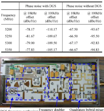
a voltage-controlled oscillator (VCO), an unequal power di-vider, an LPF, a programmable frequency prescalar, and a loop filter. Here, an integer- frequency divider, which is controlled through a three-wire serial interface, is used to control the output frequency. The loop bandwidth of the loop filter is designed to be 2.5 kHz. Additionally, the DGS is placed into the VCO in series with the varactor diode to improve the quality factor of the feedback path. The DGS cells provide a better quality factor than the other planar type resonators. Table II summarizes of the measured phase noise of the fabricated 5.25-GHz frequency synthesizer with and without DGS. According to this table, with the two-section DGS, the phase noise reduces from 10 to 16 dB. Additionally, the measured output power of the proposed struc-ture is 5.3 dBm.
IV. FABRICATION ANDEXPERIMENTAL RESULTS OF THEDOPPLERRADAR
A 10.5-GHz Doppler radar using the proposed quadrature hybrid mixer and DGS frequency synthesizer is imple-mented to detect the moving direction and ground speed of a local object. The radar front-end module is fabricated on an RO4003 substrate, as shown in Fig. 10. The Doppler radar
Fig. 9. Schematic diagram of the 5.25-GHz frequency synthesizer with two-section DGS.
TABLE II
SUMMARY OF THEPHASE-NOISEREDUCTION OF THEFREQUENCY
SYNTHESIZERWITH ANDWITHOUTDGS
Fig. 10. Photograph of the fabricated radar front-end module with quadrature hybrid mixer and DGS frequency synthesizer.
consists of a 5.25-GHz frequency synthesizer with DGS to enhance the phase-noise performance, a field-effect transistor (FET) 5.25–10.5-GHz frequency doubler designed using an FHX35LG transistor with single bias, a quadrature hybrid mixer, a 10.5-GHz bandpass filter, a baseband amplifier, and a voltage regulator. The output frequency can be synthesized from 10.4 to 10.8 GHz and the output power can also be adjusted by tuning the driving voltage to the FET frequency doubler. The baseband output of the front-end module is filtered
Fig. 11. Measured mixer output power of the Doppler radar front-end modules implemented with both the quadrature hybrid mixer and conventional quadra-ture mixer.
Fig. 12. Environment setup to assess the Doppler radar module performance in terms of acquiring the ground speed.
through an operational amplifier composed of an active LPF, which has a cutoff frequency at 100 kHz with a 20-dB/decade slope and gain of 40 dB. In this demonstration, the radar signal is transmitted and received using an -band standard horn an-tenna with 12-dBi gain, while an ARM7 based microprocessor ADuC7021 with 12-bit analog-to-digital converter (ADC) and digital-to-analog converter (DAC) is used to control the output frequency and power, acquire the baseband signal, and perform the fast Fourier transform (FFT) in order to obtain the Doppler spectrum.
Fig. 11 shows the measurement results of the receiving power obtained at the output of the first stage baseband amplifier. In this measurement, another conventional quadrature radar front-end [see Fig. 1(a)] is also implemented and measured for comparison. The conventional one is designed using the same diodes; however, with the hybrid mixers replaced by ring mixers. According to this figure, the radar front-end with the proposed quadrature hybrid mixer has about 3-dB power more in the entire region. Moreover, the mixer is optimized by adjusting the bias voltage to obtain the largest receiving power at various LO levels. The mixer performs better while at a low LO power condition. An enhancement of about 16.2 dB is achieved when the LO power is 0 dBm.
The performance of ground speed acquirement is evaluated by setting up a test environment, as shown in Fig. 12. A band
Fig. 13. Measured time-domain waveform of the baseband signal from the output of the quadrature hybrid mixer for: (a) a target with a speed of 60 km/h moving toward the sensor and (b) a target with a speed of045 km/h moving away from the sensor.
driven by a servo motor simulates the relative speed to the ground. The radar antenna is setup 30 cm above the track with a 15 tilt from the horizontal plane. Table III summarizes the Doppler shift measurements. The relative speed from 1
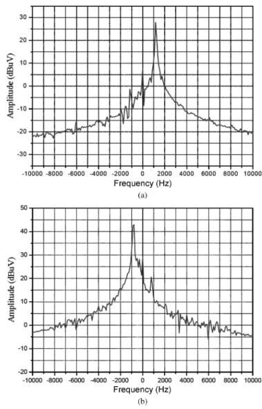
Fig. 14. Doppler frequency spectrum of the quadrature signal output from the quadrature hybrid mixer with: (a) an approaching target with a speed of 60 km/h and (b) a leaving target with a speed of045 km/h.
to 150 km/h is tested and evaluated. The measured speed correlates well to the real band speed.
The developed radar sensor architecture is tested to assess the direction and speed of an actual vehicle on the roadside. The de-tection point is in a location approximately 20 m away from the antenna; in addition, there is a 10 difference between the main-beam direction and vehicle moving direction. Fig. 13(a) and (b) shows the measured time-domain waveform at both the I and Q channels with a vehicle approaching at a velocity of 60 km/h and far away at a velocity of 45 km/h, respectively. Fig. 14 displays the calculated frequency-domain spectrum related to Fig. 13. According to this figure, the Doppler frequency shift is 1149 Hz for the approaching target at the velocity of 60 km/h, and 861 Hz for the removing target at the velocity of 45 km/h. Furthermore, the image rejection ratio is more than 25 dBc in this experiment.
V. CONCLUSION
This paper has presented a new quadrature hybrid mixer with simple devices of four 90 branch-line couplers and four mixer diodes. The proposed architecture is evaluated with 3.1-dB
LO to RF insertion loss and 15.5-dB conversion loss from RF to baseband when the LO power is 10 dBm. Only a small performance regression occurs when the LO power drops to the value as low as 0 dBm. A 5.25-GHz frequency synthesizer with the DGS is also implemented together with a frequency doubler circuitry, providing the LO signal of the quadrature mixer. It has been demonstrated that the synthesizer with DGS has a 10–16-dB phase-noise reduction than the one without DGS. A 10.5-GHz Doppler radar with the quadrature hybrid mixer and DGS frequency synthesizer is then implemented and demonstrated. The radar module can evaluate speeds as low as 0.05 km/h, which corresponds to a 1-Hz Doppler shift. The proposed architecture can also detect the sign of the Doppler shift due to the quadrature radar technology. Compared to the conventional one, the proposed quadrature radar architecture has more than 3-dB power enhancement with the same LO power level and can be optimized when the local power is reduced. This finding also implies that more than 1.2 times the detection range can be achieved. Experimental results indicate that the radar still functions when the LO power is reduced to a level below 0 dBm. Our results further demonstrates that the proposed radar architecture can operate as a roadside unit in a traffic management system to monitor the traffic flow and speed sensor in order to measure the local speed. The proposed archi-tecture also has a high local power usage efficiency, compact size, and ability to operate under a low local power condition. The proposed radar architecture with quadrature a hybrid mixer is highly promising for many radar applications.
REFERENCES
[1] H. H. Meinel, “Commercial applications of millimeter waves history, present status, and future trends,” IEEE Trans. Microw. Theory Tech., vol. 43, no. 7, pp. 1639–1653, Jul. 1995.
[2] M. E. Russell, C. A. Drubin, A. S. Marinilli, W. G. Woodington, and M. J. Del Checcolo, “Integrated automotive sensors,” IEEE Trans. Microw.
Theory Tech., vol. 50, no. 3, pp. 674–677, Mar. 2002.
[3] L. Roselli, F. Alimenti, M. Comez, V. Palazzari, F. Placentino, N. Porzi, and A. Scarponi, “A cost driven 24 GHz Doppler radar sensor development for automotive applications,” in IEEE Radar Conf., Oct. 2005, pp. 335–338.
[4] J. Wenger, “Automotive mm-wave radar: Status and trends in system design and technology,” in IEE Automot. Radar Navigat. Tech. Colloq., Feb. 1998, pp. 1/1–1/7.
[5] F. Placentino, F. Alimenti, A. Battistini, W. Bernardini, P. Mezzan-otte, V. Palazzari, S. Leone, A. Scarponi, N. Porzi, M. Comez, and L. Roselli, “Measurements of length and velocity of vehicles with a low cost sensor radar Doppler operating at 24 GHz,” in IEEE Int. Adv. Sens.
Interface Workshop, Jun. 2007, pp. 1–5.
[6] T. H. Ho and S. J. Chung, “A compact 24 GHz radar sensor for vehicle sideway-looking applications,” in IEEE Radar Conf., Oct. 2005, pp. 351–354.
[7] S. Kim and C. Nguyen, “A displacement measurement technique using millimeter-wave interferometry,” IEEE Trans. Microw. Theory Tech., vol. 51, no. 6, pp. 1724–1728, Jun. 2003.
[8] S. Kim and C. Nguyen, “On the development of a multifunction mil-limeter-wave sensor for displacement sensing and low-velocity mea-surement,” IEEE Trans. Microw. Theory Tech., vol. 52, no. 11, pp. 2503–2512, Nov. 2004.
[9] A. D. Droitcour, O. Boric-Lubecke, V. M. Lubecke, J. Lin, and G. T. A. Kovacs, “Range correlation and I/Q performance benefits in single-chip silicon Doppler radars for noncontact cardiopulmonary monitoring,” IEEE Trans. Microw. Theory Tech., vol. 52, no. 3, pp. 838–848, Mar. 2004.
[10] A. Vergara, N. Petrochilos, O. Boric-Lubecke, A. Host-Madsen, and V. Lubecke, “Blind source separation of human body motion using direct conversion Doppler radar,” in IEEE MTT-S Int. Microw. Symp. Dig., Jun. 2008, pp. 1321–1324.
[11] P. Heide, V. Magori, and R. Schwarte, “Coded 24 GHz Doppler radar sensors: A new approach to high-precision vehicle position and ground-speed sensing in railway and automobile applications,” in
Proc. Microw. Syst. Conf., May 1995, pp. 101–104.
[12] C. Fager, K. Yhland, and H. Zirath, “A balanced FET FMCW radar transceiver with improved AM noise performance,” IEEE Trans.
Mi-crow. Theory Tech., vol. 50, no. 4, pp. 1224–1227, Apr. 2002.
[13] C. Y. Kim, J. G. Kim, and S. Hong, “A quadrature radar topology with Tx leakage canceller for 24-GHz radar applications,” IEEE Trans.
Mi-crow. Theory Tech., vol. 55, no. 7, pp. 1438–1444, Jul. 2007.
[14] S. C. Song and Y. S. Hong, “A new approach for evaluating the phase noise requirements of STALO in a Doppler radar,” in Eur. Microw.
Conf., Oct. 9–12, 2007, pp. 1477–1480.
[15] E. A. M. Klumperink, S. M. Louwsma, G. J. M. Wienk, and B. Nauta, “A CMOS switched transconductor mixer,” IEEE J. Solid-State
Cir-cuits, vol. 39, no. 8, pp. 1231–1240, Apr. 2004.
[16] IE3D Electromagnetic Simulator. Zealand Softw., Fremont, CA, 2003. [17] MWOffice Linear and Non-Linear Circuit Simulator. AWR, El
Se-gundo, CA, 2004.
[18] J. W. Carr, “The stabilization of mixer diode performance against L.O. power changes with optimum DC bias,” IEEE Trans. Microw. Theory
Tech., vol. MTT-11, no. 2, pp. 123–129, Mar. 1963.
[19] D. Ahn, J. S. Park, C. S. Kim, J. Kim, Y. Qian, and T. Itoh, “A design of the low-pass filter using the novel microstrip defected ground struc-ture,” IEEE Trans. Microw. Theory Tech., vol. 49, no. 1, pp. 86–93, Jan. 2001.
[20] Y. T. Lee, J. S. Lim, J. S. Park, D. Ahn, and S. Nam, “A novel phase noise reduction technique in oscillators using defected ground struc-ture,” IEEE Microw. Wireless Compon. Lett., vol. 12, no. 2, pp. 39–41, Feb. 2002.
Tan-Hsiung Ho was born on November 27, 1980, in
Yunlin, Taiwan. He received the B.S. and M.S. de-grees in physics from National Chao-Tung Univer-sity, Hsinchu, Taiwan, in 2002 and 2003, respectively, and is currently working toward the Ph.D. degree in communication engineering in National Chiao Tung University, Hsinchu, Taiwan.
His current research interests include microwave circuitry, automotive radar systems, and antennas.
Shyh-Jong Chung (M’92–SM’06) was born in
Taipei, Taiwan. He received the B.S.E.E. and Ph.D. degrees from National Taiwan University, Taipei, Taiwan, in 1984 and 1988, respectively.
Since 1988, he has been with the Department of Communication Engineering, National Chiao Tung University, Hsinchu, Taiwan, where he is currently a Professor and Director of the Institute of Commu-nication Engineering. From September 1995 to Au-gust 1996, he was a Visiting Scholar with the Depart-ment of Electrical Engineering, Texas, A&M Uni-versity, College Station. His research interests include the design and applica-tions of active and passive planar antennas, low-temperature co-fired ceramic (LTCC)-based RF components and modules, packaging effects of microwave circuits, vehicle collision warning radars, and communications in intelligent transportation systems (ITSs).
Dr. Chung was the treasurer of IEEE Taipei Section (2001–2003) and chairman of the IEEE Microwave Theory and Techniques Society (IEEE MTT-S) Taipei Chapter (2005–2007). He was the recipient of the Outstanding Electrical Engineering Professor Award of the Chinese Institute of Electrical Engineering and the Teaching Excellence Awards of National Chiao Tung University, both in 2005.