M. R. Bai
Z. Lin
Department of Mectianical Engineering, National Cliiao-Tung University, 1001 Ta-Hsueti Rd., Hsin-Ctiu, Taiwan, Republic of Ctiina
Active Noise Canceliation for a
Three-Dimensionai Enclosure by
Using IVIultiple-Channel Adaptive
Control and Woo Control
Active noise control (ANC) techniques for a three-dimensional enclosure are com-pared in terms of two control structures and two control algorithms. The multiple-channel filtered-x least-mean-square (FXLMS) algorithm and the Ho= robust control algorithm are employed for controller synthesis. Both feedforward and feedback control structures are compared. The Youla's parameterization is employed in the formulation of the multiple-channel feedback FXLMS algorithm. The algorithms are implemented using a floating-point digital signal processor (DSP). Experiments are carried out to validate the ANC approaches for attenuation of the internal field in a rectangular wooden box. Position and number of actuators and sensors are also investigated. A broadband random noise and an engine noise are chosen as the primary noises in the experiments. The experimental results indicate that the
feedfor-ward structure yields a broader band of attenuation than the feedback structure. The FXLMS control and H«, control achieve comparable performance.
Introduction
Although Paul Lueg proposed the idea of active noise control (ANC) long before in 1936, the technique did not seem to receive full research attention. It languished until the late 1980's when the conjunction of inexpensive digital signal processors (DSP), adaptive algorithms, and application needs inspired a renaissance in this area. A good review can be found in the paper by Elhott and Nelson (1994). The ANC technique provides a useful alternative to conventional passive means. The advan-tages of ANC techniques are: improved low-frequency perfor-mance, reduction of size and weight, low cost, low back pres-sure, programmable flexibility of design, and so forth.
In viewing the ANC applications to date, much of the work has focused on cancellation of the plane-wave modes in ducts and small-volume enclosures such as headsets (Elliott and Nel-son, 1994), in which case the use of a single-channel controller is sufficient to attenuate the noise field over low-frequency ranges. On the other hand, multiple-channel ANC finds applica-tions in attenuating noise in automobile cabins and aircraft cabins (Nelson and Elliott, 1992; Kuo and Morgan, 1996). However, as compared to duct or headset applications, multiple-channel ANC systems remain less developed for full commer-cialization. The complexity of multiple-channel ANC stems from the fact that sound fields in large-volume enclosures be-come three-dimensional in nature and the high-order modes can no longer be disregarded (Kinsler et a l , 1982). It is this in-creased dimensionality of the problem that poses a severe chal-lenge for ANC techniques, especially when broadband attenua-tion is of interest (Fuller and Von Flotow, 1995). In principle, below the Schroeder's cutoff frequency, it is necessary to dis-tribute as many as possible sensors and actuators in an enclosure to achieve nearly global attenuation (Nelson and Elliott, 1992). As a general guideline, one must avoid positioning the actuators and sensors at the nodal points of the dominant acoustic modes in the enclosure. Minimization of the mean square of the sensor outputs is closely equivalent to the minimization of the global
Contributed by the Technical Committee on Vibration and Sound for publica-tion in the JOURNAL OF VIBRATION AND ACOUSTICS. Manuscript received June 1997. Associate Technical Editor: R. Clark.
acoustic potential energy (Molo and Bemhard, 1989; Lester and Fuller, 1990; Cunefare and Koopmann, 1991; Elliott et al., 1992; Bai and Chang, 1996).
In this paper, ANC techniques for a three-dimensional enclo-sure are compared in terms of two control structures and two control algorithms. The well-known multiple-input-multiple-output (MIMO) filtered-x least-mean-square (FXLMS) algo-rithm and the H„ robust control algoalgo-rithm are employed for controller synthesis. Both feedforward and feedback control structures are compared. The Youla's parameterization is em-ployed in the formulation of the MIMO feedback FXLMS algo-rithm to assure that the resulting system is internally stable. On the other hand, the //„ robust control theory provides a general and unified framework for all control structures and it makes virtually no distinction as to whether the system is single-chan-nel or multiple-chansingle-chan-nel (Doyle et al., 1989; Yeh and Yang, 1992; Tsai and Tsai, 1995). By choosing appropriate weighting functions, the H„ control theory is capable of accommodating simultaneously the requirements of robust performance and ro-bust stability in the face of modeling uncertainties and plant perturbations.
The ANC algorithms are implemented on a floating-point DSP. Experiments are carried out to validate the proposed ANC approaches for attenuation of the internal field in a rectangular wooden box. The effects of position and number of actuators and sensors on the active control are also investigated. A broad-band random noise and an engine noise are chosen as the pri-mary noises in the experiments.
Multiple-Channel Adaptive ANC Algorithms
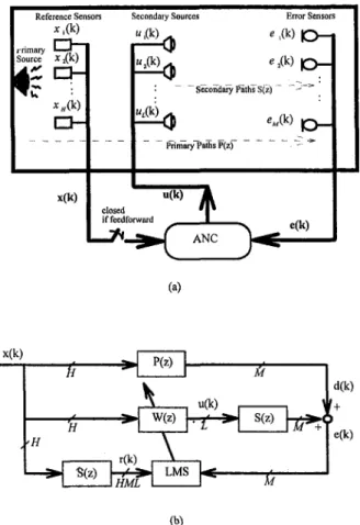
The multiple-channel feedforward and feedback FXLMS al-gorithms are presented in this section. A general MIMO ANC system using H reference sensors, L secondary sources, and M error sensors is illustrated in Fig. \(a). P(z) is the transfer matrix representing the primary paths. S(z) is the transfer ma-trix (M X L) of the secondary cancellation paths formed by actuators, acoustic error paths, and error sensors.First, the MIMO feedforward FXLMS (also known as the multiple-error FXLMS) algorithm is briefly reviewed. More detailed derivations can be found in the literature (Elliott et al.,
Enclosure
Reference Sensors Secondary Sources
x,(k) D - i w,(k) r n m a r y — - , Source X , ( K ) x(k)
"J^
um^
Error Sensors <^.(k) l O -Secondary Paths S(z) e«(k) | Q _ Primaty Paths P(zj u(k) closed if feedforward ' ^1
ANC e(k) (a) x(k) P(z) *i
W(z) •S(z) r(k) HMLI
u(k) S(z)i&*r'
LMS I T d(k) I e(k) • ; • ) • (5)The block diagram of the MIMO feedforward FXLMS algo-rithm is shown in Fig. l{b), where u(A:) is the control signal vector, W(z) is the (H X L) transfer matrix of the FIR control-ler, dik) is the primarj^ noise vector, e(k) is the error signal vector, and the matrix S(z) represents the estimate of S(z).
Next, the MIMO feedback FXLMS algorithm is derived. Consider the classical MIMO feedback structure shown in Fig. 2(a). The matrix S(z) is the transfer function of the plant (secondary path). The matrix S(z) is assumed to be stable, as is generally the case in ANC problems. The matrix C(z) is the transfer matrix of the MIMO controller. The vector u(k) is the control signal vector produced by C ( z ) . By the Youla Parame-trization (Youla et al., 1976), the set of controllers T that en-sures internal stability of the closed-loop system can be ex-pressed as
r = {W(z)[I - S ( z ) W ( z ) ] - ' | S ( z ) , W(z) e RH„ (6) where RH„ denotes the space of all proper and stable real ratio-nal transfer matrices. The block diagram of the feedback system containing a stabilizing controller C(z) e T (parametrized by W(z)) is shown in Fig. 2(b). With this setup, one can simply choose W(z) as an (L X M) FIR filter matrix (which surely &RH„) to ensure the internally stability, and adjust the coeffi-cients of W(z) via the FXLMS algorithm to minimize the resid-ual noise e(k). Let the coefficients of the L X M /-th order FIR filters be W;„„. Then the control signals Ui(k) can be written as
(b)
Fig. 1 A multiple-channel ANC problem (a) general MIMO ANC system (b) block diagram of a MIMO ANC system using the feedforward FXLMS algorithm
1987; Elliott et a l , 1992; Snyder and Hansen, 1992). In Fig. i(a), H reference signals, Xi,lk), are measured, for simplicity, by H nonacoustical reference sensors. In this study, the voltage signal driving the primary source is used as the reference. The control signals u,(k) driving the L secondary sources are pro-duced by the MIMO controller that in turn comprises L X H /-th order FIR filters with coefficients, W;*,. Then the control signals from the controller can be written as
Z Z w,i,iXi,(k
Ui(k) i). (1)
The secondary paths are modeled as 7-th order FIR filters with coefficients, s,„ij. The error signal measured by the m-th error sensor can be expressed as
L J
e„(k) = d,„(k) -I- X Z s„,jUi(k -j), (2)
1=1 J=0
where d„,(k) is the primary noise measured at the m-th error sensor. By the gradient search that seeks to minimize the cost function
M
J(k) = S ei(k), (3)
m=\
one can obtain the update formula of the filter coefficients
M
w,iu(k -f 1) = w,u(k) - // X e,„r„,i,,(k - 0 . (4) where fi is the convergence factor and r,„ii,(k) is formed by filtering the h-th reference signal by the secondary-path model from the /-th secondary source to the w-th error sensor, i.e..
r
C(z) _ u(k) d(k) S(z) e(k) (a) (b) Stabilizing Controller C(z) (c)Fig. 2 A multiple-channel feedback ANC problem (a) classical feedback ANC system (b) block diagram of a feedback system containing a stabi-lizing controller (c) block diagram of a MIMO ANC system using the feedback FXLMS algorithm
h(k) = r(k) d(k) n(k) u(k) ,^ Augmented Plant P,(z) Controller C(z) 5. ,c^^ 'z,(k) 1 z,(k) ZjCk) v(k)
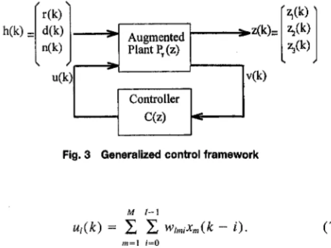
Fig. 3 Generalized control framework
M l - \
ui(k) = Z E wi„ux„ik - i). (V) Note however that the reference signals x„(k) are not directly measurable and must be synthesized by the following equation:
L J
Xmik) = E X 4(j"((fc - i) - e„{k), (8)
(=1 j=o
where *,„;, is as defined earlier. From Fig. 2{b), the residual noise can be expressed as
t{k) = A{k) + [s(fe)*w(/fc)]*x(fc), (9) where * denotes convolution. Similar to the feedforward FXLMS algorithm, it can be shown that minimizing the cost function of Eq. (3) leads to the filter update formula
M
w,„iik + 1) = w,„,i(k) - M X ei,(k)rhi„(k - i), (10) where
rumik) = X Sujx^ik - j)
J=0
(11) are the filtered synthesized reference signals; e^ = e„ and Suj = s„ij, for h = m.
The architecture of the MIMO feedback FXLMS algo-rithm is schematically shown in the block diagram of Fig. 2 ( c ) .
Multiple-Channel H^ A N C Algorithms
1. H„ Robust Control Theory. The //„ theories can be found in much control literature (e.g., Doyle et al., 1989; Iglesias and Glover, 1991; Yeh and Yang, 1992; Tsai and Tsai, 1995) and we present only the key part needed in the development of the ANC algorithms. The rest are mentioned without proof. In our study, since the system model identified by a parametric procedure is in the discrete-time domain, we present only the discrete-time version of the H„ algorithm. It is also remarked that the H„ algorithms can be divided into two classes (Lin, 1994): the model matching algorithms (the 1984 approach) and the two Riccati equation algorithms (the 1988 approach). We utilize only the latter approach, which does not require a chain of factorizations as in the model matching approach, and thus numerical problems in handling high-order (acoustical) plants can be minimized.
In modern control theory, all control structures can be cast into a generalized control framework, as depicted in Fig. 3. The framework contains a controller C ( z ) and an augmented plant Py(z). The controlled variable zik) corresponds to vari-ous control objectives Zj(^), Z2(fc), and the extranevari-ous input b(k) consists of the reference r(k), the disturbance d(fc), and the noise n(k). The signal u ( ^ ) and v(fe) are the control input to the plant and the measured output from the plant.
respectively. The general input-output relation can be ex-pressed as Z(z) V(z) P n ( z ) P2,(Z) Pi2(z) P22(Z) B(z) U(z) = Pr(z) B(z) U(z) (12)
where the submatrices P,j(z), i,j = 1, 2 are compatible parti-tions of the augmented plant Py(z) and the signal variables are capitalized to represent z-domain quntities.
The rationale of the H„ control is to minimize the infinity norm of the transfer matrix T(z) between output z(k) and the input h(k)
T(z) = P „ ( z ) + P,2(z)C(z)[I-P22(z)C(z)]-'P2,(z). (13) This is referred to as the optimal Hc„ problem (Yeh and Yang, 1992):
min||T(z)
C(z)
(14) where ||T(z)lU = sup a[T(e'")] is the infinity norm of the transfer matrix T(z) and is the maximum energy in the output from the transfer function due to any input of unit energy (a denotes the maximum singular value). However, because the optimal solution is generally difficult to obtain, one is content with the suboptimal solution: finding C(z) such that ||T(z)||„ < y, where 7 is a number which one wants to make it as small as possible. The details of the synthesis procedures of the //„ controllers per solving the Riccati equations can be found in the paper by Tsai and Tsai (1995) and are thus omitted for brevity.
2 Control Structures. In this section, feedforward and feedback structures are formulated on the basis of the general-ized control framework. The feedforward structure is illustrated in Fig. 4(a) in terms of the generalized control framework. P ( z ) , S(z), and C(z) denote the transfer matrices of the pri-mary path, the secondary path, and the MIMO controller, re-spectively. To find an H„ controller, we shall weight the output of the transfer function matrix Q(z) by Wi (z), and the control input vector u ( ^ ) by W2(z), where
Q(z) = [P(z) + S ( z ) C ( z ) ] - (15) is the transfer matrix between the disturbance d(^) and the residual noise e ( ^ ) . Note that of these weighting functions should not be confused with the FIR filter taps used in the FXLMS method. For good disturbance rejection, the nominal performance condition must be satisfied
IIQ(z)W,(z)||„ < y. (16)
In general, Wi(z) is chosen to be a lowpass function matrix with desired cutoff. The input-output relation of the augmented plant associated with the feedforward structure is
Z,(z) Z2(Z) V(z) = W , ( z ) P ( z ) 0 / Wi(z)S(z) W2(Z) 0 D(z) Viz) • (17)
Hence, as per Eq. (13), the suboptimal condition of the H„ feedforward controller reads
W , ( z ) [ P ( z ) + S ( z ) C ( z ) ]
W2(z)C(z) <y. (18)
Next, the feedback structure is illustrated in Fig. 4(b) in terms of the generalized control framework. To find an //„
d(k) u(k)
Augmented Feedforward Plant ^ (z)
V e{k)
P(z)
Tw
S(z)C(2) v(k)
(a)
Augmented Feedback Plant P (z)
(b)
Fig. 4 ANC structures in terms of the generalized control framework (a) feedforward control structure (b) feedback control structure
controller, we shall weight the sensitivity matrix S(z) by Wi(z), the control input vector u{k) by W2(z), and the com-plementary sensitivity matrix T(z) with WaCz). The sensitivity matrices S(z) and T(z) are the measures of nominal perfor-mance and robust stability and are defined as (Doyle et al., 1992)
S(z) = [ I + S(z)C(z)]- (19) and
T(z) = S(z)C(2)[I + S(z)C(z)r' = S ( z ) C ( z ) S ( z ) . (20) For good disturbance rejection and tracking performance, the nominal performance condition must be satisfied
||S(z)W,(z)|U < y.
(21)On the other hand, for system stability against plant perturba-tions and model uncertainties, the robustness condition (that can be derived from the small-gain theorem (Doyle et a l , 1992)) must be satisfied
l|t(z)W3(z)|U < y. (22) In general, W|(z) is chosen to be a lowpass function matrix, W2(z) is chosen to be a small diagonal constant matrix,_and W3(z) is chosen to be a highpass function matrix. Because S(z) + 'r(z) = I, the tradeoff between S(z) and T ( z ) , which is in turn compounded by the waterbed effect, severely dictates the performance and robustness of the feedback design. This classi-cal tradeoff renders the following mixed sensitivity problem (Yehand Yang, 1992):
|S(z)W,(z)| + | t ( z ) W 3 ( z ) | | U < 7 . (23) The input-output relation of the augmented plant associated with the feedback structure can be expressed as
Z,(z) Z2(z) Z3(Z)
LV(Z)J
-W,(z) 0 0L - I
-W,(z)S(z) WAz) W3(z)S(z)-S(z) J
U(z) Ufz) (24)Thus, as per Eq. (13), the suboptimal condition of the feedback controller reads •W,(z)S(z)-W2(z)R(z) W3(z)t(z) < y. (25) where R ( z ) = C ( z ) [ I + S ( z ) C ( z ) ] - ' = C ( z ) S ( z ) . (26) The beauty of the H^ lies in the fact that there is essentially no difference between the procedures of how one obtains the feedback controller and the feedforward controller, except the augmented matrices in Eqs. (17) and (24) are different.
Experimental Investigations
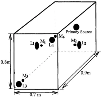
1. Experimental Arrangement. The three-dimensional enclosure used for the experiments is a rectangular wooden box with width 0.7 m, height 0.8 m, and depth 0.9 m, as shown in Fig. 5. The Schroeder's cutoff frequency of the box is approxi-mately 563 Hz, and thus our control bandwidth is targeted at 50 ~ 400 Hz. The primary noise source is mounted at the center of the far-side wall. The secondary sources Li and L2 are mounted at the centers of the opposite side walls. The secondary sources L3 and L4 are mounted at the kitty corners of the near-side wall. The error sensors Mi, M2, M3, and M4 are collocated with the secondary sources Li, L2. ^3, and L4, respectively. The voltage signal of the primary source is used as the reference signal. The algorithms are implemented on a 32-bit floating-point DSP (TMS320C31) in conjunction with a four-channel analog I/O module. The sampling rate is selected to be 2 kHz. Prior to designing the controllers, the models of the primary path P(z) and the secondary path S(z) were determined using a parametric ARX system identification procedure (Ljung, 1987). After the models are obtained, the balanced truncation tech-nique (McFarlane and Glover, 1989) is applied to reduce the
O.Sir
irrw
Table 1 The order-reduced models of the primary paths identified by the ARX procedure, where P stands for the primary plant; the subsripts 3 and 4 stand for the corresponding microphone numbers.
p, zeros -6.6131 0,0755±4.4316i -1.9451 2.7052 -0.9809 1.5131 0.3347±0.7854i 0.7090±0.6811i 0.8024±0.6453i 0.8055±0.5177i 0.9409±0.2763i 0.9936±0.0356i 0.9077±0.0554i gain = -4 z ) poles -0.9595 -0.5775±0.2500i -0.4988±0.4193i 0.4243±0.8280i 0.7I25±0.6900i 0.7498+0.60161 0.8172±0.5384i 0.8731±0.41 H i 0.9509±0.2853i 0.994a±0.0776i 0.9714±0.1232i 4102E-5 A(z) zeros -4.3696 0.5570±2.9807i -2.2667 2.6196 1.4692 0.7403±0.7110i 0.7536±0.6615i 0.8361±0.5424i 0.8082±0.4397i 0.9507±0.2558i 0.9900+0.0761i 0.9975 0.2623±0.a701i poles -0.8442 -0.7478±0.3597i 0.2091±0.8316i 0.7018±0.7G08i 0.7545±0.6463i 0.8357±0.5440i 0.8114±0.4929i 0.8914±0.4165i 0.9557±0.2769i 0.9953±0.0823i 0.9672±0.12971 gain = -1.0322E-4
orders of the models during controller design. Tables 1 and 2 give examples of the order-reduced models of the primary path and the secondary path identified by the ARX procedure.
2. Experimental Results and Discussions. In the follow-ing experimental cases, several performance indices are em-ployed to facilitate the performance comparison of the ANC methods. First, the sum of the power spectra of the error signals is defined as (global energy)
4 ( / ) = X E>nif),
(27)where E^if) denotes the power spectrum of the residual field measured at the m-th error sensor as a function of the frequency / . Then, a performance index ATTg (global attenuation)
in-tended for measuring the global control performance is defined as the total attenuation of Eg(f) over the control bandwidth (50 ~ 400 Hz)
ATTg = 10-log
/•4I
J SO
EMW
J 50 E,Af)df\, (28)where the subscripts "u" and "c" stand for "uncontrolled"
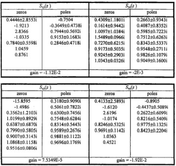
Table 2 The order-reduced models of the secondary paths identified by the ARX procedure, where S stands for the secondary plant; the sub-scripts correspond to the speaker input and the microphone output.
S„(z) zeros 0"4446±2'.'8553i -1.9213 2.8366 -1.0335 0.7840±0.5598i 1.0459 0.8761 poles -0.7504 -0.3649±0.4738i 0.7944±0.5692i 0.9153±0.1683i 0.2846±0.4718i gain = -1.12E-2 5„(z) zeros 0.4309±1.18011 0.1614±0.9442i 1.0097±1.03841 1.5489±0.0966i 0.7270±0.6215i 0.9173±0.5035i 0.9245±0.2903i 1.0343±0.0326i poles 0.2663±0.9343i 0.4087±0.8352i a.5985±0.7223i 0.7512±0.6263i 0.8343±0.5337i 0.9548±0.2711i 0.9826±0.1079i 0.9049±0.1600i gain = -2E-3 S zeros -15.8595 -1.4986 0.3562±1.21031 1.0199±0.8929i 0.6387±0.6870i 0.7990±0.5805i 0.9007±0.3143i 1.0868±0.11581 0.9516±0.0806i gain = ,*) poles 0.3180±0.90901 0.506!±0.7822i 0.6300±0.7456i 0.7548±0.6284i 0.8314±0.5443i 0.9589±0.2676i 0.9881+0.11221 0.9696±0.1769i 7.5349E-5 St zeros 0.413312.58931 -1.6120 2.6196 -1.0174 0.8246±0.5325i 0.969110.1142i 1.0363 0.4521 gain = (^) poles -0.8905 -0.443710.50891 0.262210.60991 0.821610.54091 0.977510.13251 0.842310.22041 1.92E-2
Table 3 Experiment cases (Part 1). The effects of number and position of sensors and actuators on ANC are investigated using the feedforward FXLIVIS algorithm.
Primary noise: band-limited {0~400 Hz) random noise. ANC method: MIMO feedforward FXLMS algorithm. Case 1(a) 1(b) 2 3(a) 3(b) 3(c) 4 Secondary source(s) L, L4 L4 L[, Lj I-i, L, L „ L . L|, Lj, L4 Error sensor(s) M, M, M „ M , M i . M ; Mj, M4 M „ M 3 M|, Mj, M, Performance ATT, = 0.42dB, ATT, = 5.18 dB ATT, = 0.53dB, ATT, = 8.16 dB ATT, = 0.63dB, ATTj = -0.12 dB, ATT, = 7.53 dB ATT, = 0.68 dB, ATT, = 3.96 dB, ATT, = 5.80 dB ATT, = 1.86 dB, ATT, = 8.12 dB, ATT, = 7.31 dB ATT, =-2.88 dB, ATT, = 1.89 dB, ATTj = 2.78 dB ATT, = 2.62dB, ATT, = 2.94 dB, ATTj = -0.02 dB ATT, = 8.10 dB, ATT, = 5.12 dB
and "controlled", respectively. Third, a performance index A7T„ intended for measuring local control performance at the OT-th error sensor is defined as the total attenuation of E„(f) over the control bandwidth 50 ~ 400 Hz
ATT,„= 10-log
( / :
E,M)df
J 50E,M)df . (29)
Experiments were carried out to investigate the MIMO ANC techniques. The primary noise type, ANC algorithm, number of actuators and sensors, and the results for each test case are summarized in Tables 3 and 4. In part 1 of the experimental cases (Table 3), we first examine the effects of the position and number of actuators and sensors on the MIMO active control. A band-Umited (0 ~ 400 Hz) random noise is used as the primary noise. The ANC method is the MIMO feedforward FXLMS algorithm. In Case 1(a), we use only one secondary source L^ and one error sensor Mi. The total attenuation ATTi achieved at M\ is 5.18 dB. In Case 1 (b), we use L4 as the actuator and M4 as the error sensor. Maximum attenuation reaches 17 dB and A7T4 is 0.53 dB. The results suggest that single actuator-sensor pair can provide local attenuation and the pair placed at the comer are more effective than those at the center of the wall. It is remarked that the references by Bai and Chang (1996), and by Molo and Bemhard (1989) seem to have different views from the reference by Cunefare and Koopman (1991) regarding the optimal allocation of sensors and actuators in active control: the first two references suggest placing sensors and actuators at the pressure maxima, while the last reference suggests placing sensors and actuators at the particle velocity maxima. Our ex-perimental results appear to agree better with the conclusions in the first two references. In Case 2, we use one secondary source L4 and two error sensors, M^ and M4. Attenuation is found only at the sensor M4. In Case 3 ( a ) , we use two second-ary sources Li, L2, and two error sensors Mi, and M2. The total attenuation ATTg is 0.68 dB after the ANC is activated. Case 3(b) shows the results when the collocated transducers Z.3, L4, M3, and M4 are used, where ATTg is 1.86 dB, ATT^ and ATT^ are 8.12 dB and 7.31 dB, respectively. Case 3 ( c ) shows the results when two noncollocated actuator-sensor pairs, L3, L4,
Ml, and M2 are used. Although total attenuations of 1.89 dB and 2.78 dB in the band 50 ~ 400 Hz at M, and M2 are obtained, the sound pressure is increased at M3 and M4. This amounts to an ATTg of -2.88 dB. The results of this case suggest that collocated actuator-sensor pairs placed at the corners provide the largest noise cancellation. In Case 4, three collocated actua-tor-sensor pairs, Li — Mi, L^ — M3, and L4 — M4, are used. A total attenuation 2.62 dB of Eg{f) is obtained after the ANC is activated, which is the largest among the four cases.
From the above results in part I, the guidelines for locating of sensors and actuators in an ANC system can be summarized as follows. Collocated actuator-sensor pairs provide better per-formance than the non-collocated pairs. This is a well-known fact in structural control: that the transfer functions of collocated pairs have less non-minimal phase (NMP) zeros which impose design constraints on the control system (Miu, 1991). A suffi-cient number of sensors and actuators are needed for achieving global control. Furthermore, it is preferable to locate actuator-sensor pairs at the corners of the enclosure, where pressure maxima correspond to the best controllability and observability for the actuators and sensors.
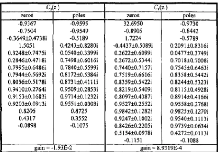
Next, the performance of the MIMO ANC methods based on different control structures and algorithms are investigated. In all cases, L3 and L4 are used as the secondary sources, and M3 and M4 are used as the error sensors. The band-limited random noise is used as the primary noise. The results obtained from the feedforward FXLMS algorithm, the feedback FXLMS rithm, the feedforward //»= algorithm, and the feedback H„ algo-rithm are compared in Cases 1 and 2. ATTg for these four methods are 1.86 dB, 0.98 dB, 2.73 dB, and 0.24 dB, respec-tively. The results show that the feedforward structure is more effective than the feedback structure in suppressing broadband random noises. Among the ANC methods, the MIMO feedfor-ward Hoo algorithm produces the largest total reduction ofEg(f). The poles and zeros of the MIMO feedforward Hoo controller are listed in Table 5.
Table 4 Experimental cases (Part 2). Multiple-channel ANC methods based on different control algorithms and structures are investigated.
Table 5 A list of poles and zeros of the feedforward H„ controller, where C stands for the controller; the subsripts 3 and 4 stand for the corre-sponding speaker numbers.
Secondary sources: Lj, L^ Error sensors: M3, M4 Case 1 2(a) 2(b) 2(c) 3(a) 3(b) 3(c) 3(d) ANC method feedforward FXLMS feedback FXLMS feedforward / 4 feedback //„ feedforward FXLMS feedback FXLMS feedforward H^ feedback //„ Noise type random noise random noise random noise random noise engine noise engine noise engine noise engine noise Performance ATT,= L86dB, ATTj = 8.12 dB, ATT, = 7.31 dB ATT, = 0.98 dB, ATTj = 1.25 dB, ATT, = 2.11 dB ATT, = 2.73 dB, ATT, = 6.16 dB, ATT, = 5.17 dB ATT, = 0.24 dB, ATTj = 0.59 dB, ATT, = 0.39 dB ATT, = 4.31dB, ATTJ = 11.20 dB, ATT, = 18.34 dB ATT, = 3.73 dB, ATTj = 11.33 dB, ATT, = 20.76 dB ATT, = 5.08 dB, ATTj = 11.24 dB, ATT, = 7.86 dB ATT, = 3.14 dB, ATT, = 6.21 dB, ATT, = 5.84 dB C,(z) zeros -0.9367 -0.7504 -0.3649±0.4738i 1.5051 0.3248±0.7475i 0.2846±0.4718i 0.7995±0.6486i 0.7944±0.5692i 0.8056±0.5178i 0.9410±0.2764i 0.9153±0.1683i 0.9203±0.0913i 0.8206 0.4317 -0.0898 poles -0.9595 -0.9549 -0.5189 0.4243±0.8280i 0.0540±0.3399i 0.7498±0.6016i 0.7840±0,5599i 0.8172±0.5384i 0.873110.41 Hi 0.9509±0.2853i 0.9714±0.1232i 0.955 l±0.0303i 0.8725 0.3552 -0,1075 gain = -1.93E-2 C,(z) zeros 32.6950 -0.8905 1.7224 -0.4437±0.5089i 0.2622±0.6099i 0.2672±0.5344i 0.744010.7157i 0.7519±0.6616i 0.8359±0.5422i 0.8219±0.5409i 0.8097±0.4387i 0.9527±0.2552i 0.9842±0.1282i 0.9247±0.1002i 0.8426±0.2205i 0.5154±0.0978i -0.1151 poles -0.9730 -0.8442 -0.5789 0.209110.83161 0.0477±0.3749i 0.7018±0.7008i 0.7545±0.6463i 0.8358±0.5442i 0.8244±0.5323i 0.8115±0.4928i 0.8914±0.4166i 0.9558±0.2768i 0.9825+0.12701 0.954010.11131 0.973910.06341 0.427210.01131 -0.1088 gain = 8.9319E-4
Next, in Case 3, exhaust noise from the gasoline engine op-erating at 4,000 rpm is chosen as a more practical primary noise. The ATTg obtained by using the feedforward FXLMS algorithm, the feedback FXLMS algorithm, the feedforward //„, algorithm, and the feedback Hoo algorithm are 4.31 dB, 3.73 dB, 5.08 dB, and 3.14 dB, respectively. The feedforward Ho^ algorithm again yields the largest global attenuation of Eg(f).
Concluding Remarks
Multiple-channel ANC systems based on the FXLMS algo-rithm and the //„ algoalgo-rithm are investigated. Both feedforward and feedback ANC structures are investigated. Experiments are carried out to compare the ANC approaches for attenuation of the internal field in an enclosure. Number and position of actua-tors and sensors required to achieve global control is also exam-ined.
Insofar as the allocation of sensors and actuators is concerned, a useful strategy is to place a sufficient number of collocated actuator-sensor pairs to create connected quiet zones distributed in the enclosure. In particular, it is preferred to place the actua-tor-sensor pairs in the regions of pressure maxima.
All ANC algorithms yield significant noise reductions for periodic (engine) noises. For a high-order plant such as the enclosure in our case, the feedforward structure appears to be a more viable approach for broadband cancellation. The feedback structure suffers from the waterbed effect and only narrowband noise rejection can be achieved. The adaptive methods and the //„ methods exhibit comparable performance for both random noise and engine noise irrespective of the control structure. However, only the MIMO feedforward //»technique is effective in suppressing transient noises.
One important issue that is not addressed in this paper is the acoustic feedback problem associated with the feedforward structure. In some practical situations, only acoustical reference signals sensed by upstream microphones are available so that one is faced with the problem of acoustic feedback. This will considerably complicate the MIMO control design from the standpoint of performance and robustness. The future investiga-tions will focus on this particular aspect.
Acknowledgment
The work was supported by the National Science Council in Taiwan, Republic of China, under the project number NSC 86-2212-E-009-003.
References
Bai, M. R., and Chang, S., 1996, "Active Noise Control of Enclosed Harmonic Fields by Using BEM-Based Optimization Techniques," Applied Acoustics, Vol. 48, No. 1, pp. 15-32.
Cunefare, K. A., and Koopman, G. H., 1991, " A Boundary Element Approach to Optimization of Active Noise Control Sources on Three-Dimensional Struc-tures," ASME, JOURNAL OF VIBRATION AND ACOUSTICS, Vol. 113, pp. 387-394.
Doyle, J. C , Francis, B. A., and Tannenbaum, A. R., 1992, Feedback Control Theory, MacmiUan Publishing Company, New York.
Doyle, J. C , Glover, K., Khargonekar, P., and Francis', B. A., 1989, "State Space Solution to Standard H^ and //« Control Problems," IEEE Trans, on Auto-matic Control, Vol. AC-34, No. 8, pp. 832-847.
Elliott, S, J., and Nelson, P. A., 1994, "Active Noise Control," Noise/News International, Vol. 2, No. 2, pp. 75-98.
Elliott, S. J., Boucher, C. C , and Nelson, P. A., 1992, "The Behavior of a Multiple Channel Active Control System," IEEE Transactions on Signal Pro-cessing, Vol. 40, No. 5, pp. 1041-1052.
Elliott, S. J., Nelson, P. A., Stothers, I. M., and Boucher, C. C , 1990, "In-Flight Experiments on the Active Control of Propeller-Induced Cabin Noise," Journal of Sound and Vibration, Vol. 140, pp. 219-238.
Elliott, S. J., Stothers, I. M., and Nelson, P. A., 1987, " A Multiple Error LMS Algorithm and Its Application to the Active Control of Sound and Vibration," IEEE Transactions on Acoustics, Speech, and Signal Processing, Vol. ASSP-35, No. 10, pp. 1423-1434.
Fuller, C. R., and Von Flotow, A. H., 1995, "Active Control of Sound and Vibration," IEEE Control Systems Magazine, Vol. 2, pp. 9-19.
Iglesias, P. A., and Glover, K., 1991, "State-Space Approach to Discrete-Time //„ Control," International Journal of Control, Vol. 54, pp. 1031-1072.
Kinsler, L. E., Frey, A. R., Coppens, A. B., and Sanders, J. V., 1982, Funda-mentals of Acoustics, 3rd Ed., John Wiley and Sons, New York.
Kuo, S. M., and Morgan, D. R., 1996, Active Noise Control Systems, John Wiley and Sons, New York.
Lester, H. C , and Fuller, C. R., 1990, "Active Control of Propeller-Induced Noise Fields inside a Flexible Cylinder," AIAA Journal, Vol. 28, No. 8, pp. 1374-1380.
Lin, C. F., 1994, Advanced Control Systems Design, Prentice-Hall, Englewood Cliffs.
Ljung, L., 1987, System Identification: Theory for the User, Prentice-Hall, Englewood Cliffs.
McFarlane, D. C , and Glover, K., 1989, Robust Controller Design Using Nor-malized Coprime Factor Plant Design, Springer-Verlag, Berlin.
Miu, D. K., 1991, "Physical Interpretation of Transfer Function Zeros for Simple Control Systems with Mechanical Flexibilities," ASME Journal of Dy-namic Systems, Measurement, and Control, Vol. 113, pp. 419-424.
Molo, C. G., and Bernhard, R. J., 1989, "Generalized Method of Predicting Optimal Performance of Active Noise Controllers," AIAA Journal, Vol. 27, No. 11, pp. 1473-1478.
Nelson, P. A., and EUiott, S. J., 1992, Active Control of Sound, Academic Press, San Diego.
Snyder, S. D., and Hansen, C. H., 1992, "Design Considerations for Active Noise Control Systems Implementing the Multiple Input, Multiple Output LMS Algorithm," Journal of Sound and Vibration, Vol. 159, pp. 157-174.
Tsai, M. C , and Tsai, C. S., 1995, "A Transfer Matrix Framework Approach to the Synthesis of H^ Controllers," International Journal of Control, Vol. 5, pp. 155-173.
Yeh, F. B., and Yang, C. D., 1992, Post Modern Control Theory and Design, Eurasia, Taipei, Taiwan.
Youla, D. C , Jabr, H. A., and Bongiorno, J. J., 1976, "Modern Wiener-Hopf Design of Optimal Controllers, Part 2; the Multivariable Case," IEEE Trans. Auto. Control, Vol. 21, pp. 319-338.