DESIGN STRATEGY FOR THREE-DIMENSIONAL SUBBAND FILTER BANKS
Po-Cheng Wu, Liang-Gee Chen, Yeong-Kang Lai, and
Tsung-Han Tsai
Lab.
332, Department
ofElectrical Engineering
National Taiwan University
Taipei, Taiwan,
R.O.C.
E-mail:
pcwu8video.ee.ntu.edu.tw
ABSTRACT
Since three-dimensional (3-D) subband coding has been introduced, most researches on 3-D subband cod- ing perform temporal filtering first. In this paper, how- ever, we investigate the best permutation strategy for temporal, vertical, and horizontal filtering to minimize the requirement of delay elements and find that the results are opposite to our expectation.
1. INTRODUCTION
Recently, there has been rapid progress in the area of multirate digital signal processing. Applications of multirate systems include subband coding of video and audio signals, fast transforms using digital filter banks, wavelet analysis, and many others [1]-[3]. One of the most important applications of multirate systems is subband coding (SBC). Since it was introduced by Cro- chiere et al. [4] in 1976, subband coding has been an effective coding approach for video and audio appli- cations [5]-[7]. Subband coding employs a filter bank
for splitting the input signal, so the filter banks are es- sential t o subband coding. Because filter banks usually deal with a large number of data, high speed computing hardware is indispensable for subband coding systems. Subband coding was first extended to three dimen- sional (temporal, vertical, and horizontal) filtering, i.e.,
3-D
subband coding, by Karlsson and Vetterli 281. S- ince then, most researches which deal with 3-D sub- band coding perform temporal filtering first, e.g., [8]- [13]. Since 3-D subband coding requires a large numberof delay elements to store the intermediate data, delay elements dominate the hardware cost in this coding scheme. Therefore, the most important task remains how t o minimize the requirement of delay elements. In this paper, we investigate the best permutation strat- egy for temporal, vertical, and horizontal filtering in different conditions in order t o minimize the required number of delay elements.
0-7803-3258-X/96/$5.00 0 1996 IEEE 605
2. DESIGN STRATEGY
Let us assume the video format is M lines x N pixels x P frames/sec, and the numbers of filter taps for tem- poral, vertical, and horizontal filtering are x + 1, y
+
1, and z+
1, respectively. Thus, the required numbersof delay elements for temporal, vertical, and horizontal filtering are MNx, Ny, and z, respectively. In sub- band coding, we usually employ the FIR direct form filter. The advantage of employing the FIR direct for- m is that the lowpass filter and the highpass filter can share the same delay elements.
2.1. E i g h t - N l Bands
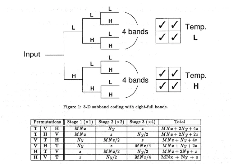
We will first consider 3-D subband coding with eight- full bands as shown in Fig. 1. From Fig. 1, we find that by employing the FIR direct form filters, stage
1 requires one set of dela,y elements; stage 2 requires two sets of delay elements; stage 3 requires four sets of delay elements. The required numbers of delay ele- ments for different permutations of temporal, vertical, and horizontal filtering are listed in Table 1. Note that the filtering results are identical even though the fil- tering permutations are different. From Table l , we find that for eight-full-band splitting, the cascade s-
trategy, which requires the minimum number of delay elements, is horizontal, vertical, followed by temporal filtering, i.e., (H, V, T).
2.2. Four-Reduced Bands
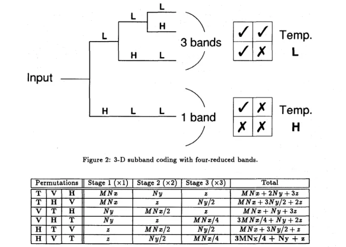
In order to achieve a high compression ratio in 3-D sub- band coding, we often discard the four higher bands as
shown in Fig. 2. Thus, from Fig. 2, we find that stage 1 requires one set of delay elements; stage 2 requires two sets of delay elements; stage 3 requires three sets
of delay elements. The reiquired numbers of delay ele- ments for different permutations are listed in Table 2. From Table 2, we find that, for four-reduced-band split- ting, the cascade strategy which minimizes the delay
I
S
S
Figure 1: 3-D subband coding with eight-full bands.
I
PermutationsIJ
Stage 1 ( X I )I
Stage 2 ( x 2 )I
Stage 3 ( x 4 )I
TotalI
Table 1: Comparison of the required delay elements for different filtering permutations in 3-D subband coding with eight-full bands.
elements is horizontal, vertical, followed by temporal filtering, i.e., (H, V, T).
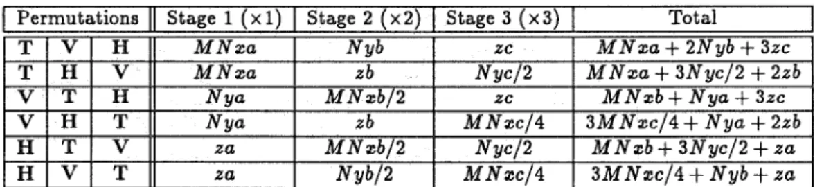
2.3. Finite Wordlength
E
Finally, if we further consider the finite wordlength ef- fect t o enhance the accuracy of subband coding, we assume that the wordlengths of delay elements in stage 1, stage 2, and stage 3 are a, b, and c bits, respec- tively. The relation between a, b, and c is usually a
5
b5
c. Now, we still look at 3-D subband coding with four-reduced bands. The required numbers of de- lay elements for different permutations are listed in Ta-ble 3. From Table 3, we are unable to distinguish which permutation strategy is the best choice. Therefore, we make the following assumptions: the video format is M = 512 lines and N = 1024 pixels; the temporal filter has x
+
1 = 2 taps (in order to minimize the de- lay time); the vertical filter has y+
l = 8 taps; the horizontal filter has 2;+
1 = 16 taps; the wordlengths of delay elements in stage 1, stage 2, and stage 3 area = 8 , b = 9, and c = 10 bits, respectively. After care- ful calculation, we find that if we consider the finite wordlength effect in the above conditions, the cascade strategy which minimizes the delay elements is vertical, horizontal, followed by temporal filtering, i.e., (V, H,
TI.
3. CONCLUSI
From above discussion, we find that the results are op- posite to our expectation. Performing the temporal filtering first is not the best strategy. On the contrary, placing the temporal filter at final stage will save the delay elements. We also find that the best permutation strategy for temporal, vertical, and horizontal filtering depends on different conditions. Finally, for the syn-
thesis filter banks or a higher number of filtering stages in 3-D subband coding, by employing the same scheme, we can also derive the best permutation strategy which minimizes the requirement of delay elements.
Input
Permutations T l V l H
1
Stage 1 (
x
1) Stage 2 ( ~ 2 ) Stage 3 ( ~ 3 ) TotalM N x NY z
I
H
L
L
T l H l VI
M N x z\
/
\
/
3 bands
1
band
N u l 2Temp.
L
Temp.
H
I I V T H V H T H T V H V TFigure 2: 3-D subband coding with four-reduced bands;.
I I, NY M N x / 2 z
NY z
2 NY/2
z
M N x / 2Table 2: Comparison of the required delay elements for different filtering permutations in 3-D subband coding with four-reduced bands.
4. REFERENCES
R. E. Crochiere and L. R. Rabiner, Multirate Digi- tal Signal Processing. Englewood Cliffs, NJ: Pren-
tice Hall, 1983.
P. P. Vaidyanathan, Multirate Systems and Filter
Banks. Englewood Cliffs, NJ: Prentice Hall, 1993.
N. J . Fliege, Multirate Digital Signal Processing. New York: Wiley, 1994.
R. E. Crochiere, S. A. Webber, and J. L. Flanagan, “Digital coding of speech in subbands,” Bell Syst.
Tech. J., vol. 55, pp. 1069-1085, Oct. 1976.
J. W. Woods and S. D. O’Neil, “Subband cod- ing of images,” IEEE Trans. Acoust., Speech, Sig-
nal Processing, vol. ASSP-34, pp. 1278-1288, Oct.
1986.
H.
Gharavi, “Subband coding algorithms for video applications: videophone to HDTV-conferencing,”IEEE Trans. Circuits Syst. Video Technol., vol. 1,
no. 2, pp. 174-183, June 1991.
[7] E.
B.
Richardson and N. S . Jayant, “Subband cod- ing with adaptive prediction for 56 kbits/s audio,” IEEE Trans. Acoust., Speech, Signal Processing, vol. ASSP-34, pp. 6!31-696, Aug. 1986.[8] G. Karlsson and
M.
Vetterli, “Three dimension- al sub-band coding of video,” in Proc. IEEE Int.Conf. Acoust., Speech, Signal Processing, 1988, p-
p. 1100-1103.
[9] J. Hartung, “Architecture for real-time implemen- tation of three-dimlensional subband video cod- ing,” in Proc. IEEE Int. Symp. Circuits Syst., vol.
3, 1992, pp. 225-228.
[lo] K. N. Ngan and W. L. Chooi, “Very low bit rate video coding using ;ID subband approach,” IEEE
Trans. Circuits Syst,, Video Technol., vol. 4, no. 3,
pp. 309-316, June 1!994.
Permutations
11
Stage 1 ( X I )I
Stage 2 ( x 2 )1
Stage 3 ( x 3 )I
TotalI
Table 3: Comparison of the required delay elements for different filtering permutations considering the finite wordlength effect in 3-D subband coding with four-reduced bands.
[ll] C. I. Podilchuk, N. S. Jayant, and N. Farvard-
m, “Three-dimensional subband coding of video,”
IEEE Trans. Image Processing, vol. 4, no. 2, pp.
125-139, Feb. 1995.
[12] F. Fan, S. Simon, I. Bruyland, W. Zhu, B.
D.
Canne, and M. V. Bladel, “A method for hier- archical subband HDTV splitting,” IEEE Trans.Circuits Syst. Video Technol., vol. 5, no. 3, pp.
225-230, June 1995.
[13] C. H . Chou and C. W. Chen, “A perceptually op- timized 3-D subband codec for video communica tion over wireless channels,” IEEE Trans. Circuits
Syst. Video Technol., vol. 6, no. 2, pp. 143-156,
Apr. 1996.