行政院國家科學委員會專題研究計畫 成果報告
氧化錳奈米線結構鋰離子電池正極材料的電化學性質探討
研究成果報告(精簡版)
計 畫 類 別 : 個別型 計 畫 編 號 : NSC 95-2221-E-151-053- 執 行 期 間 : 95 年 08 月 01 日至 96 年 07 月 31 日 執 行 單 位 : 國立高雄應用科技大學化學工程與材料工程系 計 畫 主 持 人 : 吳茂松 計畫參與人員: 碩士班研究生-兼任助理:李榮浩 處 理 方 式 : 本計畫可公開查詢中 華 民 國 96 年 09 月 29 日
行政院國家科學委員會補助專題研究計畫
▓ 成 果 報 告
□期中進度報告
奈米結構氧化錳電極合成及其在鋰離子電池的應用
計畫類別:■ 個別型計畫
□ 整合型計畫
計畫編號:NSC 95-2221-E-151-053-
執行期間:95 年 08 月 01 日至 96 年 07 月 31 日
計畫主持人:吳茂松
共同主持人:
計畫參與人員:李榮浩
成果報告類型(依經費核定清單規定繳交):■精簡報告
□完整報告
本成果報告包括以下應繳交之附件:
□赴國外出差或研習心得報告一份
□赴大陸地區出差或研習心得報告一份
□出席國際學術會議心得報告及發表之論文各一份
□國際合作研究計畫國外研究報告書一份
處理方式:除產學合作研究計畫、提升產業技術及人才培育研究計畫、
列管計畫及下列情形者外,得立即公開查詢
□涉及專利或其他智慧財產權,□一年□二年後可公開查詢
執行單位:國立高雄應用科技大學化學工程與材料工程系
中
華
民
國
96 年
09
月
29 日
附件一1
氧化錳奈米線結構鋰離子電池正極材料的電化學性質探討
Electrochemical investigations on nanowire structure of manganese oxide cathode for lithium-ion batteries
計畫編號:NSC 95-2221-E-151-053 執行期限:95年08月01日 至 96年07月31日
主持人:吳茂松 國立高雄應用科技大學化學工程與材料工程系
1.Abstract
Nanostructured manganese oxide electrodes are fabricated directly by electrochemical deposition. Surface morphology of the electrode deposited at high current density shows nanowires with diameter 12-16 nm distributed randomly. Nanowires tend to aggregate to clumps when the deposition current density is low. Both annealing temperature and deposition current density affect the intercalation and deintercalation of lithium ions within the deposited manganese oxide cathode in an aqueous lithium sulfate electrolyte. An optimal annealing temperature is found to be 300 oC in terms of the electrode’s specific capacity during high-rate charging/discharging. An electrode with thinner nanowires deposited at high current density has a high specific capacity because thinner nanowires shorten the diffusion of lithium ions and in favor of high-rate charging/discharging.
Keywords: manganese oxide, lithium
storage, cathode material, nanostructured materials, and aqueous lithium-ion batteries.
2. Introduction
There are many different forms of manganese dioxide such as-MnO2,-MnO2,
and -MnO2 for lithium battery cathode
material. Generally, crystal structure of the manganese oxides influences intercalation and deintercalation of lithium ions during electrochemical reaction. -MnO2 has low
electrochemical stability because it contains (2 × 2) tunnels within its structure [1-4]. To enhance the structural instability of -MnO2, cations such as Ba2+ or K+were added during synthesis because they can take up crystallographic sites within the (2×2) tunnels [4]. Although structural stability of -MnO2 has been improved by cation addition, a drawback is that electrochemical performance would be significantly limited by a cation-hindered and hence lowered diffusion rate of lithium ions [4,5].
-MnO2 structure is more stable in the
manganese dioxide family because its structure consists of narrow (1×1) tunnels [4]. However, this stable structure obstructs the intercalation and deintercalation of lithium ions, therefore results a low capacity [6]. Specific capacity of -MnO2 can be much improved by decreasing the degree of crystallinity, but the charge/discharge reaction can not be fully reversed [7,8]. -MnO2 structure consists of intergrown domains of
-MnO2 and ramsdellite-MnO2 in which the
ramsdellite-MnO2 embeds (2×1) tunnels [4,9]. Reports have stated the reversible intercalation and deintercalation of lithium ions occur mainly in the ramsdellite-MnO2 domain of -MnO2 [10,11]. Generally, chemical or electrochemical synthesized
-MnO2 material contains water on the grain
surface or grain boundary. Water can be removed by heating the substance to 375 oC [12].
Nanostructured materials play an important role in electrochemical performance because high specific surface area and fast redox reactions enhance electrochemical behavior of the applied battery. Generally, lithium ion diffusion within the crystal structure of active material dominates the high-rate charging and discharging of the electrode. Diffusion resistance of lithium ions within the material can be decreased by shortening the diffusion path; therefore, nanostructure is advantageous in improving the high-rate performances of materials. However, an electrode composed of nanoparticles is more difficult to fabricate by the traditional slurry coating method, because nanoparticles have poor dispersibility in slurry (composed of solvent, nanoparticles, polymer binder, and conducting agent, etc.). West et al. [13] have proposed a synthesis method for preparing the manganese oxide array by deposition of the manganese oxide sol-gel within the porous template. Sugantha et al. [14] deposited the manganese oxide in a porous template to form array electrode and demonstrated a much improved high-rate performance. Using a template method to synthesize nanostructured materials, the template will need to be removed after synthesis. Thus, it is more advantageous to have an electrode of nano-sized manganese oxide fabricated by electrochemical deposition which deposits the active material directly onto the substrate at room temperature without any template and/or catalyst. Electrochemical deposition technique has one advantage over all the others: weight and thickness of the metal oxide film may be easily controlled by controlling the current, bath composition, and bath temperature.
Most of the researches on lithium-ion
batteries are focused on the nonaqueous electrolyte. Recently, Li et al. [15-17] have proposed a type of rechargeable lithium batteries with aqueous electrolyte. Aqueous lithium-ion battery is one of the promising candidates for energy storage in terms of safety and cost. More recently, Wang et al. [18-20] have proposed a hybrid aqueous energy storage cell using LiMn2O4, LiCoO2, and LiCo1/3Ni1/3Mn1/3O2 as the positive electrode and activated carbon as the negative electrode. Therefore, in this work, the electrochemically anodic deposition method is used to fabricate manganese oxide directly onto a stainless steel substrate. In addition, electrochemical performance of the synthesized manganese oxide is investigated in an aqueous electrolyte.
3. Experimental
Nanostructured manganese oxide electrodes were electrochemically deposited onto stainless steel (SS) foils (22 cm2
) by applying two current densities of 0.125 mAcm-2 and 0.025 mAcm-2, respectively. The plating solution consisted of 0.1 M manganous acetate and 0.1 M sodium sulfate at room temperature [21-23]. A saturated calomel electrode (SCE) was used as the reference electrode and a platinum foil with dimension 22 cm2
was used as the counter electrode. Prior to deposition, SS foils were polished with emery paper, and washed in acetone and deionized water, respectively. The plating solution was stirred by a Teflon stir on a magnetic hot plate during the entire deposition. After deposition, the deposited foils were rinsed several times in deionized water and dried at various temperatures for 1 h in air. The amount of deposited manganese oxide was measured by a microbalance (Ohaus G160, USA) with an accuracy of 0.01
3
mg. Surface morphology of the
electrochemically deposited electrode was examined with a scanning electron microscope (FE-SEM, Jeol JEOL-6330, USA) with an accelerating voltage of 15 keV. Crystal structures of the deposited manganese oxide were identified by a glance angle X-ray diffractometer (GAXRD, Rigaku D/ MAX2500, Japan) with a Cu K target (wavelength = 1.54056 Å). A beaker-type electrochemical cell comprised of a working electrode (manganese oxide electrode), a counter electrode (platinum foil), and a reference electrode (SCE) was used to determine the electrochemical performance of deposited manganese oxide electrodes. The electrolyte was 1 M lithium sulfate (Li2SO4) aqueous solution. Charge/discharge and cycle-life stability were performed by a charge/discharge unit (Hokuto Denko HJ-201B, Japan) in the potential range of 0 V to 1.1 V versus SCE at constant current. All data acquisition functions in Hokuto Denko were carried out through an interface card (Labjack U12, USA) with LabVIEW software. Electrodes were charged at constant current to a cutoff potential of 1.1 V versus SCE. Discharge was performed at the same rate to a cutoff potential of 0 V versus SCE. Cyclic voltammetry (CV) measurements were taken by means of a potentiostat/galvanostat (CH Instruments CHI 608, USA). The potential was cycled in the range of 0 V to 1.2 V versus SCE at a scan rate of 25 mVs-1.
4. Results and discussion
Previous results indicated that the deposited manganese oxides of annealing temperatures lower than 300 oC resemble closely to -Mn(O,OH)2(-manganese oxide hydroxide), but it decomposes to Mn2O3 at temperatures beyond 500 oC [24]. In order to avoid
structural destruction by water contamination, the annealing temperature has been set at 300 o
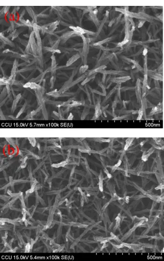
C. Figure 1 shows the surface morphology of manganese oxide electrode deposited electrochemically at different current densities after annealing at 300 oC for 1 h. Morphology of the deposited manganese oxide at a high current density of 0.125 mAcm-2 (Fig. 1a) shows nanowires with diameter of 12~16 nm and distributes randomly on the SS substrate. Nanowires tend to aggregate into clumps of diameter about 100 nm (Fig. 1b) when current density is decreased to 0.025 mAcm-2. Current density of the deposition is important in controlling the surface morphology of the deposited manganese oxide film, which in turns affect its electrochemical performance. It is generally believed that nano-structured materials have higher specific surface area and fast redox reactions; in addition, ion diffusion within the structure dominates high-rate charging and discharging performances of the electrode. Diffusion resistance of ions (lithium ions) within the materials can be mitigated by shortening the diffusion path; therefore, electrode materials with nano-sized wires may be advantageous in high-rate performances. Figure 2 shows the cyclic voltammograms of the deposited manganese oxide electrodes after annealing at different temperatures: electrolyte is 1 M Li2SO4 aqueous solution and CV scan rate is 25 mVs-1. The potential was cycled between 0 V and 1.2 V versus SCE corresponding to a range of 3.3 V to 4.5 V versus Li/Li+in nonaqueous electrolyte. When the heating temperature exceeds 200 oC, two distinct redox current peaks may be observed: an anodic peak at ca. 0.9 V and a cathodic peak at ca. 0.75 V versus SCE. Based on previous reports [25,26], appearances of redox peaks indicate an irreversible intercalation/
deintercalation of lithium ions in solid phase with charge transfer on the electrode/ electrolyte interface. Electrode after annealing at 300 oC has the highest current response in cyclic voltammogram, indicating the largest storage capacity for lithium ions at this annealing temperature.
Figure 3 shows surface morphology of the deposited manganese oxide electrode at full intercalated and deintercalated states. Electrode was deposited at 0.125 mAcm-2and annealed at 300oC for 1 h. After intercalation and deintercalation of lithium ions, morphology of nanowires remains almost unchanged except a small volumetric expansion at the deintercalated state as compared with the intercalated state; which is quite different from manganese oxide used in anode in a nonaqueous electrolyte. Previous results showed that surface morphology of manganese oxide electrode treated at 300 oC has changed drastically after charging from 3.0 V to 0.01 V versus Li/Li+ [24,27]. Lithium-storage process in manganese oxide anode is unlike the process in cathode because morphology after lithium intercalation does not changed significantly, it only expands a little volumetrically.
Figure 4 shows the charge
(deintercalation) and discharge (intercalation) curves of the deposited manganese oxide electrode at different charging/discharging current densities. Electrode was electrochemically deposited at 0.125 mAcm-2 and annealed at 300 oC for 1 h. At charging/discharging current density of 1.15 Ag-1, charge capacity of 70 mAhg-1 is almost the same as the discharge capacity. With a higher charging/discharging current density of 18.4 Ag-1, the electrode capacity reaches 54 mAh g-1. Specific capacity decreases only
slightly by increasing the current, meaning that the synthesized manganese oxide electrode is insensitive and tolerates high-rate charging and discharging. Possibly, this insensitivity results from its nanowire structure: large electroactive area for fast redox reaction, and shortened diffusion paths for high-rate charging/discharging.
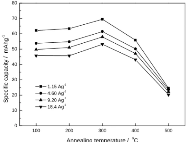
Figure 5 shows the combined effect of annealing temperature and discharging current density on specific capacity of the electrochemically deposited manganese oxide electrode. The relationships show that annealing temperature influences remarkably the specific capacity of electrode at all charging/discharging current ranges. Specific capacity value increases with annealing temperature, but it reaches a maximum at 300 o
C, and decreases with further increase in annealing temperature. The deposited film annealed at 300 oC shows a superior performance in high-rate charge/discharge capability: the film has a specific capacity of about 70 mAhg-1 at discharging current density 1.15 Ag-1, and 54 mAg-1at 18.4 Ag-1. Previous reports suggested that annealing temperature affects crystal structure of the electrochemically deposited manganese oxide [28-31]. According to Preisler [29], only a small percentage of water in the electrodeposited manganese dioxide is volatile at 120 oC, and a predominant portion of water is desorbed in a relatively smooth manner up to 350 oC. In addition, the electrodeposited manganese oxide decomposes rapidly to form Mn2O3 at temperatures exceeds 500 oC [28]. Water content within is known to affect the electrochemical reactivity and the thermodynamic stability of various manganese oxide phases as water causes variations in crystal lattice and consequently in electrical
5 conductivity and electrode potential1 [30,31]. Moreover, water creates challenges in lithium battery application because of lithium instability with water and decomposition of water during charge/discharge processes.
Specific capacity of the electrode after annealing at 100 oC is lower than that annealed at 300 oC. Hydrated water content affects lithium ion storage in the manganese oxide electrode; therefore an electrode after 300 oC annealing has the highest specific capacity in all discharging current densities, because water has largely been removed by this high temperature. For temperature higher than 500 oC, the deposited manganese oxide decomposes to Mn2O3. A structural change such as this may affect the intercalation and deintercalation of lithium ions, therefore decreasing its specific capacity.
Figure 6 shows the effect of electrochemical deposition current density on the specific capacity of manganese oxide. Specific capacity of the manganese oxide electrode deposited at high current density of 0.125 mAcm-2 is higher than that of low current density of 0.025 mAcm-2. As mentioned previously, morphology of the manganese oxide changes with the current density during deposition. Electrode deposited at high current density of 0.125 mAcm-2 consists of nanowires with diameter 12-16 nm distributed randomly on the SS substrate. These distributed nanowires facilitate intercalation and deintercalation of lithium ions, possibly, due to both the increased active surface area and the shortened diffusion path. An electrode deposited at low current density of 0.025 mAcm-2 has nanowires in clumps which lead to an increased diffusion resistance. It is generally believed that redox reactions in manganese oxide electrode involve lithium
ion intercalation into the electrode, while lithium ions diffusion (mass-transfer resistance) controls the specific capacity at high-rate discharging. Therefore, an electrode with distributed nanowires has the highest specific capacity throughout the entire measured current density range because these nanowires shorten the proton diffusion and in favor of high-rate charging/discharging. In addition, electrode of high depositing current has a highly porous structure for electrolyte access, which also improves the high-rate discharge capability.
Figure 7a shows the effect of annealing temperature on cycle-life stability of the deposited manganese oxide electrode. Charging and discharging current density are set at 4.6 Ag-1. For electrodes annealed below 300 oC, a poor stability is observed: specific capacity decreases from 62 mAhg-1 to 50 mAhg-1 after 150 charging/discharging cycles. Hydrated water content is believed to affects cycle-life performance. From Fig. 7a, an enhanced cycle-life performance is seen with increasing the annealing temperature. However, electrodes annealed at temperatures exceeding 300oC have very little difference in their cycle-life performance, because most hydrated water content has already been removed. Figure 7b shows the effect of electrochemical depositing current density on cycle-life stability of the manganese oxides after annealing at 300 oC for 1 h. The effect is small. Therefore, cycle-life stability of a deposited manganese oxide electrode is mainly determined by the annealing temperature rather than the current density during deposition.
5. Conclusion
Electrochemical deposition current density plays an important role in controlling
the surface morphology of a deposited manganese oxide film. Morphology of the deposited manganese oxide is changed from random distributed nanowires (about 12-16 nm in diameter) to aggregated nanowire clumps (about 100 nm in diameter) by varying the current density from 0.125 mAcm-2 to 0.025 mAcm-2. Both annealing temperature and current density during deposition affect the intercalation and deintercalation of lithium ions within the deposited manganese oxide materials. Water which impedes lithium intercalation in hydrated manganese oxide is decreased by increasing the annealing temperature. After a threshold temperature of 300 oC, electrodes show a high specific capacity in all discharging current densities, because most water has already been removed.
The structural change caused by
decomposition of the deposited manganese oxide at high temperature affects the intercalation/deintercalation of lithium ions, therefore decreasing its specific capacity. In addition, specific capacity is increased by increasing the deposition current density due to a decreased diameter of the nanowires. Electrode deposited at a high current density has a high specific capacity throughout the entire discharge current range because of its small nanowire diameter; narrow nanowires provides more active sites for charge transfer and shortens proton diffusion, therefore benefits the high-rate charging and discharging.
References
1. M.H. Rossouw, D.C. Liles, M.M. Thackeray, W.I.F. David, S. Hull, Mater. Res. Bull. 27 (1992) 221.
2. M.H. Rossouw, D.C. Liles, M.M. Thackeray, W.I.F. David, S. Hull, Prog. Batt. and Batt. Mater. 15 (1995) 8.
3. C.S. Johnson, D.W. Dees, M.F. Mansuetto, M.M. Thackeray, D.R. Vissers, D. Argyriou, C.K. Loong, L. Christensen, J. Power Sources 68 (1997) 570.
4. M.M. Thackeray, in Handbook of Battery Materials, J.O. Besenhard, ed., Wiely-VCH, NY, p.293 (1999).
5. T.Ohzuku, M. Kitagawa, K. Sawai, T. Hirai, J. Electrochem. Soc. 138 (1991) 360.
6. D.W. Murphy, F.J. Di Salvo, J.N. Carides, J.V. Waszczak, Mater. Res. Bull. 13 (1978) 1359. 7. M.M. Thackeray, Prog. Batt. and Batt. Mater.
14 (1995) 1.
8. M.M. Thackeray, A. de Kock, L.A. de Picciotto, G. Pistoia, J. Power Sources 26 (1989) 355.
9. Y. Chabre, J. Pannetier, Prog. Solid State Chem. 23 (1995) 1.
10. T. Ohzuku, M. Kitagawa, T. Hirai, J. Electrochem. Soc. 136 (1989) 3169.
11. T. Ohzuku, M. Kitagawa, T. Hirai, J. Electrochem. Soc. 137 (1990) 40.
12. H. Ikeda, S. Narukawa, J. Power Sources 26 (1983) 329.
13. W.C. West, N.V. Myung, J.F. Whitacre, B.V. Ratnakumar, J. Power Sources 126 (2004) 203.
14. M. Sugantha, P.A. Ramakrishnan, A.M. Hermann, C.P. Warmsingh, D.S. Ginley, Int. J. Hydrogen Energy 28 (2003) 597.
15. W. Li, J.R Dahn, D.S Wainwright, Since 264 (1994) 1115.
16. W. Li, W.R. Mckinnon, J.R. Dahn, J. Electrochem. Soc. 141 (1994) 2310.
17. W. Li, J.R Dahn, J. Electrochem. Soc. 142 (1995) 1742.
18. Y.G. Wang, Y.Y. Xia, J. Electrochem. Soc. 153 (2006) A450.
19. Y.G. Wang, J.Y. Luo, C.X. Wang, Y.Y. Xia, J. Electrochem. Soc. 153 (2006) A1425.
20. Y.G. Wang, J.Y. Luo, W. Wu, C.X. Wang, Y.Y. Xia, J. Electrochem. Soc. 154 (2007) A228. 21. D. Tench, L.F. Warren, J. Electrochem. Soc.
130 (1983) 869.
22. M.S. Wu, P.C. Chiang, Electrochem. Solid-State Lett. 7 (2004) A123.
7
23. M.S. Wu, J.T. Lee, Y.Y. Wang, C.C. Wan, J. Phys. Chem. B 108 (2004) 16331.
24. M.S. Wu, P.C. Chiang, J.T. Lee, J.C. Lin, J. Phys. Chem. B 109 (2005) 23279.
25. A. Yuan, Q. Zhang, Electrochem. Commun. 8 (2006) 1173.
26. M. Manickam, P. Singh, T.B. Issa, S. Thurgate, R.D. Macro, J. Power Sources 130 (2004) 254.
27. M.S. Wu, P.C. Chiang, Electrochem. Commun. 8 (2006) 383.
28. Y. Omomo, T. Sasaki, M. Watanabe, Solid State Ionics 151 (2002) 243.
29. E. Preisler, J. Appl. Electrochem. 6 (1976) 311.
30. S.C. Pang, M.A. Anderson, T.W. Chapman, J. Electrochem. Soc. 147 (2000) 444.
31. A. Era, Z. Takehara, S. Yoshizawa, Electrochim. Acta 12 (1967) 1199.
Figures
Fig.1Surface morphology of the manganese oxide electrode deposited electrochemically at current density of 0.125 mAcm-2(a) and 0.025 mAcm-2(b) after annealing at 300oC for 1 h.
0.0 0.2 0.4 0.6 0.8 1.0 1.2 -20 -15 -10 -5 0 5 10 15 20 3.3 3.6 3.9 4.2 4.5 100o C 400 o C 300o C C u rr e n t d e n s it y / m A g -1 Potential / V vs. SCE 100o C 200o C 300o C 400o C 500o C 500o C Potential / V vs. Li/Li+
Fig. 2 Cyclic voltammograms of deposited
manganese oxide electrodes after annealing at different temperatures for 1 h.
Fig. 3 Surface morphology of the deposited
manganese oxide electrode at fully intercalated state (a) and fully deintercalate d state (b).
(a)
(a)
(b)
0 10 20 30 40 50 60 70 80 0.0 0.2 0.4 0.6 0.8 1.0 1.2 3.2 3.4 3.6 3.8 4.0 4.2 4.4 de-intercalaction P o te n ti a l / V v s . S C E
Specific capacity / mAhg-1
1.15 Ag-1 4.60 Ag-1 9.20 Ag-1 18.4 Ag-1 intercalaction P o te n ti a l / V v s . L i/ L i +
Fig. 4 Charge and discharge curves of the
deposited manganese oxide electrode at different charging/discharging current densities.
100 200 300 400 500 0 10 20 30 40 50 60 70 80 S p e c if ic c a p a c it y / m A h g -1 Annealing temperature / oC 1.15 Ag-1 4.60 Ag-1 9.20 Ag-1 18.4 Ag-1
Fig. 5 Effect of annealing temperature and
discharging current density on the specific capacity of the electrochemically deposited manganese oxide electrode.
0 4 8 12 16 20 0 10 20 30 40 50 60 70 80 S p e c if ic c a p a c it y / m A h g -1 Current density / Ag-1 0.125 mAcm-2 0.025 mAcm-2
Fig. 6 Effect of current density during
electrochemical deposition on the specific capacity of the deposited manganese oxide under different discharging current densities.
0 20 40 60 80 (b) S p e c if ic c a p a c it y / m A h g -1 100o C 200o C 300o C 400o C 500o C (a) 0 50 100 150 200 250 300 0 20 40 60 80 Cycle no. 0.125 mAcm-2 0.025 mAcm-2
Fig. 7 Effect of annealing temperature (a) and
deposition current density (b) on the cycle-life stability of deposited manganese oxide electrode. Charging and discharging current density are set at 4.6 Ag-1.