Improving
TCP
Performance in Heterogeneous Mobile Networks.
Chang-Jung Kao
',
Wanjiun Liaoz, and Chin-Hei Chien Jen-Chi LiuComputer Communications Lab.
DeDartment of Electrical Engineering
-
National Taiwan UniversityTaipei, Taiwan Absrmcr- I n this paper, a new transport mechanism is
proposed to improve TCP performance in heterogeneous
mobile networks. The proposed mechanism is comprised of two parts: a Congestion Predictor (CP) and a Bandwidth Estimator (BE). Based on the CP, the cause of a packet loss during roaming is determined. If the loss is considered caused by congestion in the wireline, the congestion window
is halved; otherwise, the packet is considered lost in the last hop, the wireless portion, and the sender can adjust the
growth of the congestion window based on the BE. Hence, our mechanism can adapt to heterogeneous wireless
network environment and also enhance TCP performance.
We have conducted simulations to evaluate the performance
of the proposed mechanism. The results show that o u r
mechanism significantly improves TCP performance as
compared to existing solutions in heterogeneous mobile
networks.
Keywords- wireless TCP, mobile networks
I. INTORDUCTION
TCP is a transport layer protocol providing reliable and ordered data. service in the Internet. While TCP performs well in wired networks, when used in mobile wireless networks, TCP performance may degrade due to high bit error rates on the wireless link or temporary disconnections caused by handoffs. Much research effort has been expended to
enable wireless or mobile TCP. Existing work on this subject can he classified into two categories: (1) approaches based on base station assistance, such as I-TCP [l], MTCP [2], Snoop [3], M-TCP [4], and WTCP [SI, and (2) end-to-end approaches, such as
Fast retransmission [6], Explicit Bad State Notification [7], and Freeze TCP [8].
~
I T N Hsinchu, Taiwan
In this paper, we will focus on the performance problem with temporary disconnections caused by handoffs, and propose an end-to-end mechanism to improve TCP performance for roaming users in mobile networks. Such disconnections may further result in the following problems: (1) data loss during the handoff period, and (2) throughput degradation due to handoffs. To solve this problem, the proposed mechanism is comprised of two pans: a Congestion Predictor (CP) and a Bandwidth Estimator (BE). The CP targets the first issue and determines the reason of a packet loss during the handoff period; the BE focuses on the second issue, and improves the throughput of the connection after handoffs. Note that most of the existing work focuses on the enhancement of TCP performance over wireless networks at the receiver side, i.e., the operation will he performed at the receiver side. In this paper, we will discuss this problem from the perspective of the sender.
The rest of the paper is organized as follows. Sec.
11 describes the proposed mechanism. Sec. 111 shows the simulation results to evaluate the performance of the proposed mechanism. Finally, the paper is concluded in Sec. 1V.
11. PROPOSED MECHANISM
The proposed mechanism is comprised of two parts: a Congestion Predictor (CP) and a Bandwidth Estimator (BE). We assume that there is a reliable link layer protocol between the mobile node and the base station, and the TCP module will be notified by lower layer protocols about the start and the finish of
a handoff.
' This work was supported in part by the MOE program for Promoting Academic Excellence of Universities under grant number 89E-FA06-2-4-7, and in part by the National Science Council, Taiwan, under grant number NSC91-22 13-E-002-048.
'
This author is now with Quanta Computer Inc. in Taiwan.*
This author is also with the Graduate Institute of Communications Engineering, and the Department of Computer Science and Information Engineering, National Taiwan University, Taipei, Taiwan. Email: [email protected] 0-7803-7757-5/03/$17.00 02003 IEEE. 1735t
Trx_time+snrr
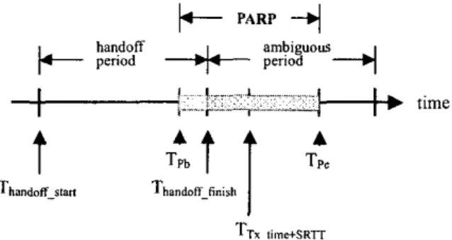
Figure 1. lllustration of PARP
A . Congestion Predictor
(CP)
The Congestion Predictor is used to determine why packets are not received after handoffs. The
loss of a packet during a handoff may be caused by congestion in the wireline, or by handoffs, or by transmission errors on the wireless channel. Only in the congestion case should the congestion window of the TCP sender be shrunk to half that of the normal TCP operation.
To determine the cause of a packet loss, two loss probabilities are calculated PH and Pc. PH is the probability that a loss is caused by the handoff, and Pc, the loss is due to congestion. If PC > PH, the mechanism considers the loss caused by congestion, and the normal congestion control mechanism is initiated; otherwise, the loss is due to handoffs, and
the
sender
can continue sending unsent packets inthe usable window size based on the Bandwidth Estimator (BE) which will he described later.
reason of packet losses is ambiguous
To determine PH, the sender checks if the PARP
of a lost packet is within the handoff period. If the PARP falls within the handoff period, PH is set to
Max (i.e. 100%). If the PARP is completely beyond
the handoff period, PH is set to Min (i.e. 0%). If the
PARP is within the ambiguous period,
PH
will be calculated as4,
= Th0"d"f.5",$h- TPb
T,
- TPb
Pc
is calculated based on the congestion historya , which is the ratio of RTT to SRTT (i.e. RTT =
aSRTT). Whenever segment losses are detected, excluding the losses occurring in the ambiguous period. the congestion histow,
-
a, will be calculatedRTT
1
valueas follows. aSvmplr =
,
andSR TT
a,,,
=w,
xa,
+
(1-
w,)
xasomp.
,
where w, is theweighting factor, e.g. 0.2. The RTT-value is set to an RTO value if the reason of segment loss is retransmission timeout; otherwise, the RTT-value is We briefly describe how PH and PC are
calculated. When a timeout occurs, a period called Possible ACK returning Period (PARF') will be
calculated according to eqs. (1) and (2). set to the sampled RTT. Tpb = the beginning time of the PARP
Tp, = the end time of the PARF' =
=
Transmit-time
+
SRTT
-RTTVAR (1)Transmit-time
+
SRTT+
RTTVAR (2)If RTT is less than SRTT,
Pc
is set toMin
(i.e. 0%); if RTT is greater than aSRTT, Pc is set to Mar(i.e. 100%). Otherwise, P, will he obtained as Here SRTT means smoothed RTT and RTTVAR
means RTT variation. Fig. 1 illustrates PARF', which is the period from Tpb to Tpe. Note that after a handoff, there is a short period called the ambiguous period (e.g., IxSRTT). During this period, the
RTT
a x S R 7 T
Pc =
TCP Receiver
i . ."... .~ .... ^. ""___'
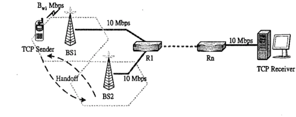
Figure 2. Simulation environment
B. Bandwidth Estimator (BE)
The Bandwidth Estimator is used to determine how to grow the congestion window after a handoff. For homogeneous networks, the sender will increase the congestion window after the handoff if the TCP sender cannot send segments to the receiver due to an empty usable window. The additional window size increased by BE is the amount which should have increased during the handoff period. In BE, an acknowledgement interval is calculated, which is used to evaluate the inter-arrival time of acknowledgements. Based on the value of the handoff period and the acknowledgement interval time, a fair amount of increase in congestion window can be determined. For heterogeneous networks, the BE can also adapt to the bandwidth accordingly based on the bandwidth condition after the handoff.
111. PERFORMANCE EVALUATION
In this section, we will describe the simulations conducted to evaluate the performance of the proposed mechanism in a wireless network. The
There is an FTP connection between the TCP sender and the receiver. The FTP connection lasts for the duration of the simulation. The value of each parameter is listed as follows: n=3, B,I = IOMbps, BwZ = IOMbps, and Thandoff_frcq= 20 sec, and D,= 100
ms.
The simulation results are generated using two simulation tools: OPNET and ns-2. We compare the following mechanisms in the simulation: TCP Reno and Fast Retransmit with Freeze timer.
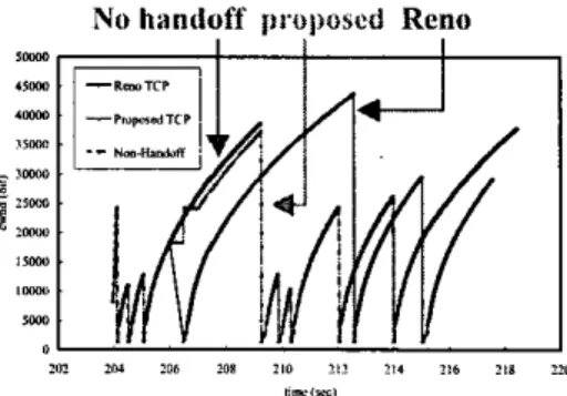
Fig. 3 plots the congestion windows of the
proposed mechanism and TCP Reno. The curves for Reno and the proposed mechanism are plotted after a handoff. The curve marked "no-handoff' is for comparison, showing the congestion window of a Reno connection when no handoff occurs. We see that the proposed mechanism performs as if the handoff has never occurred, while Reno degrades when a handoff occurs. Fig. 4 shows the throughput gains of the proposed mechanism over TCP Reno, varying the handoff duration from 0 to 3 sec. The gain is defined as
Gain = ~ x100%
Throughput,,
~*
Thro~ghpufprwed~,
-
ThroughpufRm r psimulation environment is shown in Fig. 2. There are n routers between a base station (BS) and a wired
.
The curve with diamonds is with CP only (the receiver. The on each wired link is set to ~ ~ ~ ~ ~ 50 ~ ~ ms. ~~~~~ One), the curve with rectangles is with BE
The proposed m&&m is imp1 emen ted at the only (the hottom one), and the curve with triangles is mobile sender. The mobile sender moves between with both (the top One). we see that cp is more
BSI and BS2 every the time interval ThandoE-heq = important than BE in terms of the throughput improvement for mobile TCP connections in our
is defined as how long the mobile stays in a cell. The mechanism. The three have performance
smaller value ofThando~-dwa,ion. the more frequently a gains higher than one, indicating that ''0 handoff is performed. The data rates of the wireless mechanism outperforms TCP Reno.
links to BSI and BS2 are set to B,, and B,?,
respectively. The wireless delay D, is a variable. Fig. 5 shows the performance gain of the 1/Thandoff_duration. The handoff duration 1/Thandoff_duntion
proposed mechanism over a TCP variant having both freeze timer and fast retransmit mechanism. Since Freeze TCP and existing work focus on the receiver side, we implement the combined mechanism of Freeze TCP [8] with Fast Retransmit
[ 6 ] at the sender and compare with our mechanism. The curve with diamonds (the upper one) is for the proposed mechanism, and the one with rectangles is for the combined freeze timer and fast retransmit. Again, varying the handoff duration from 0 to 3 sec., we see that our mechanism o u t p e r f o m Fast Retransmit with Freeze Timer.
IV. CONCLUDING REMARKS
In this paper, we have proposed an end-to-end mechanism which improves the performance of TCP for heterogeneous mobile networks. The
proposed mechanism is comprised of two parts: a Congestion Predictor (CP) and a Bandwidth Estimator (BE). CP determines why packets are not received after bandoffs, and BE determines bow to grow the congestion window aAer bandoffs. We have also conducted simulations to evaluate the performance of our mechanism. The results show that the proposed mechanism significantly improves TCP performance for wireless networks.
REFERENCES
[I] A. Bakre and B. R. Badrinath, “I-TCP Indirect TCP for Mobile Hosts,” Proc. of the I S h lntemational Conference on Distributed Computing Systems, June
1995.
[2] I. Rhee, N. Balaguru, and G.N. Rouskas, “MTCP: Scalable TCP-like Congestion Control for Reliable Multicast,” IEEE INFOCOM ‘99,1999.
[3] H. Balakrishnan, S. Seshan, and R.H. Katz, “Improving Reliable Transport and Handoff Performance in Cellular Wireless Networks,” ACM Wireless Networks, Dec. 1995.
[4] K. Brown and S. Singh, “M-TCP: TCP for Mobile Cellular Networks,” ACM Computer Communications Review, vol. 27, 1997.
[ 5 ] P. Sinha, et al., “WTCP A Reliable Transport Protocol for Wireless Wide-Area Networks”, Mobicom’99, 1999.
[6] R. Caceres and L. IAode, “Improving the Performance of Reliable Transport Protocols in Mobile Computing Environments,” IEEE Journal on Selected Areas in
Communications, June 1995.
[7]
B.
S. Bakshi, P. Krishna, N. H. Vaidya, and D. K. Pradhan, “Improving Performance of TCP over Wireless Networks,” lntemational Conference on Distributed Computing Systems, 1997.[8] T. Goff, J. Moronski, D. S. Phatak, and V. Gupta,
“Freeze-TCP: A True End-to-End TCP Enhancement Mechanism for Mobile Environments,” IEEE INFOCOM ’00,2000.
No
handoff rtroi;oaed Reno”.Irr,
Figure 3. TCP Reno vs. proposed TCP
<wmbmwD&,- *w,m hd,Sm. C W D -h.,hn
0 1 8.5 M“w.I..MI-,
Figure 4. The impact of the two components of the proposed mechanism on the performance
0 5 , I I ,
Hu.b”Ol.N“ls%,
Figure 5 . Fast Retransmit