4102 IEEE TRANSACTIONS ON MAGNETICS, VOL. 43, NO. 12, DECEMBER 2007
Innovative Three-Axial Actuator for High-Density Optical Drive
Yung-Sung Lan
1;2and Chung-Hao Tien
3Department of Photonics and Institute of Electro-Optical Engineering, National Chiao Tung University, Hsinchu, Taiwan Electronics and Optoelectronics Research Laboratories, ITRI, Hsinchu, Taiwan
Department of Photonics and Display Institute, National Chiao Tung University, Hsinchu, Taiwan
As the density in optical data storage systems increases, a drive capable of tilt control thus becomes necessary in order to improve the tilt margin as the coma aberration is accordingly increased. In this paper, we propose an innovative three-axial actuator based on a traditional four-wire scheme with an additional pair of tilting magnets. The proposed coil-driven servo can independently compensate 1 tilt degree associated with a torque variation of less than 5%. The driving forces of the focusing and tracking are kept constant while the tilt servo is activated.
Index Terms—Electromagnetic force, magnetization, optical pickup actuator, three-axis.
I. INTRODUCTION
T
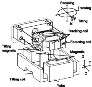
HE prerequisite for achieving a diffraction-limited spot is to reduce the aberrations in the disk system. However, as the recording density is developed toward a higher numerical aperture (NA), the coma aberration which is proportional to the NA has become more critical and the radial tilt compensation is thus required [1]–[5]. Nowadays, there are two methods to implement the function of three degrees of freedom (focusing, tracking, and tilting) control. Mohri et al. [6] used four perma-nent tilting magnets located on the moving part of a three-axial actuator to share the coils with the focusing mechanism. On the other hand, Lee et al. [7] proposed to locate the tilt magnets onto the yoke, which allows high-speed acceleration, but ac-companying a larger volume of the overall system. The advan-tage of the former approach lies in that the tilting coils do not need an extra pair of wires to provide a driving current. Based on such scheme, we developed a three-axial servo composed of a traditional four-wire actuator and an additional pair of tilting magnets to further accomplish the compactness of size. The ra-dial tilting magnets are positioned under the moving part where compensation for tilting can be independently actuated. A de-tailed perspective of the actuator is presented in Fig. 1, where the overall configuration consists of a lens-holder, one pair of focusing, tracking, and tilting coils, repsectively. The torque around the Z-axis parallel to the tangential direction of the disc is generated by the tilting coils. In such case, since the three pairs of coils are current-driven by independent permanent magnets, the issue under investigation is how to ensure the absence of in-teference between each function while maintaining an adequate response time.II. DESIGNCONCEPT
In order to eliminate the rotational mode, the mass center of the moving part shall coincide with the line of the driving force. We thus placed the center of the focusing and tracking coils onto the mass center of the moving part at neutral position. In
Digital Object Identifier 10.1109/TMAG.2007.906461
Color versions of one or more of the figures in this paper are available online at http://ieeexplore.ieee.org.
Fig. 1. Enlarged perspective view of the three-axial.
addition, the weight of the moving part needs to be balanced in order for the actuator to operate properly [8]. It is useful to keep the tilting magnets below the moving part to balance the heavy weight of the high NA objective lens, which is located above the lens-holder.
If the actuator is driven in a rolling direction when the laser beam was focused onto the media in both focusing and tracking direction, a change in focus occurs in each direction. Due to the offset, the beam spot becomes unfocused again. Reducing the access time is an approach; however, it easily leads to the de-terioration of playability [7]. Therefore, we yield the rotational center to be coincident with the nodal point of the object lens since the optical performance of the image plane will not be affected after the actuator is located at the correct position of the disk when the moving part rotates. A three-axial actuator has been developed using six wires along with mutually inde-pendent focusing, tracking, and tilting magnets. However, the tilting coils are difficult to attach precisely onto the lens-holder due to its small size. We thus shift the position of the tilting coils to yoke to avoid the assembly error.
III. VIBRATIONANALYSIS ANDMODALANALYSIS The finite-element method (FEM) was employed to evaluate the dynamic characteristics of the actuator. The motion of the 0018-9464/$25.00 © 2007 IEEE
LAN AND TIEN: INNOVATIVE THREE-AXIAL ACTUATOR FOR HIGH-DENSITY OPTICAL DRIVE 4103
Fig. 2. Mode shapes of (a) second resonant frequency and (b) higher order resonant frequency.
actuator in X, Y, and Z directions can be assumed as a second order linear system:
(1) (2) (3) (4) (5) (6) where is the mass of the moving part; and are the magnetic forces in the focusing and tracking directions, respec-tively; is the magnetic moment in the Z direction; is the damping coefficient and is the moment inertia of the moving part; is the focusing and tracking spring constants; is the twisting spring constant; and are the force constants in the focusing, tracking, and tilting directions; and are the voltage applying at the coils. Therefore, the nat-ural frequency and of the motion can be obtained using the following equations:
focus and track (7)
twist (8)
From (7) and (8), the resonant frequency is determined by the rigidity of the suspension and the mass of the moving
part (0.37 g). In the case of g, kgf/m,
kgf m, kg m , the natural
frequency is obtained as 61 Hz (focus and track) and 106.3 Hz (twist), respectively. The high resonant frequencies would lead to lens tilting because the lens-holder is deformed when the high resonance occurs. In this paper, we use finite-el-ement software ANSYS to simulate the mode shapes of the lens-holder as shown in Fig. 2. The high resonant frequencies can be determined by this program.
IV. MAGNETICFIELDANALYSIS
The magnetic flux distribution plays an important role in the actuator design as well. In order to produce a high and uniform magnetic flux density field, a full finite-element model com-posed of three pairs of magnets and three pairs of coils is an-alyzed using the vector-potential, Newton–Raphson approach [11]–[13]. The purpose of the finite-element method is to re-veal the flux density distribution, magnetic forces, and torques
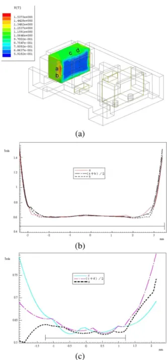
Fig. 3. Finite-element-model analysis of the VCM. (a) Magnetic flux density field for the movable space of tracking and focusing coils. (b) Magnetic flux density field of lines a and b (The effective length of focusing coil is from+3:3 to03:3 mm). (c) Magnetic flux density field of lines c and d (the effective length of tracking coil is from+1.3 to 01.3 mm).
by using finite-element software ANSOFT. Therefore, the ac-tuator with an objective lens can be driven at a high response speed. Thus, the number of trial and error prototypes will be minimized, and an optimum design will be achieved during the development of the prototype.
Focusing and Tracking Coils: Since a focusing coil has a
longer magnetic flux than that of the other coils, the corre-sponding driving force would not influenced by the position of the focusing coil in X direction. Consequently, a focusing coil is used as the mass balancer to address the imbalance between the force center and the mass center. Furthermore, the force center of the tracking coils must be consistent with the mass
4104 IEEE TRANSACTIONS ON MAGNETICS, VOL. 43, NO. 12, DECEMBER 2007
Fig. 4. Arrangement of magnets for the VCM.
Fig. 5. Force of the tilting magnets in variation position of X, Y, and Z direction.
Fig. 6. Force distribution of focusing and tracking and torque distribution of tilting at variation tilting angles.
center of the moving parts due to the reason that the imbalance between the force and mass center would cause subresonance when the actuator is driven in the tracking direction. As shown in Fig. 3(a), the linear area in the movable range of the focusing coil is from line a to b, and the tracking coil is from line c to d, where line a and b represent the focusing coil moving from the equilibrium above to below, as shown in Fig. 3(b), lines c and d represent the tracking coil moving from position left to right, as shown in Fig. 3(c). According to Fig. 3, the permitted movement ranges for tracking and focusing are between 0.7 and 0.4 mm, respectively. In addition, 80% of the effective focusing coil length and 70% of the effective tracking coil length are 0.6 T. The tilting angle in full stroke of tracking direction is larger than that in the focusing direction. This problem can be solved by adjusting the position of the magnets to obtain a more even magnetic flux density in full stroke of tracking direction.
Tilting Magnets: In this design process, we first decide the
direction of the tilting magnetic poles, as shown in Fig. 4(a). Arrangement A is proven to be more stable than arrangement B
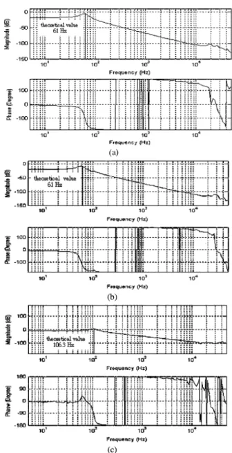
Fig. 7. Bode plot of (a) focusing, (b) tracking, and (c) tilting direction.
by the magnetic testing analysis. The best neutral vertical po-sition of the tilting magnets can be detemined at
mm in Fig. 4(b), where the net force is minimal at this
posi-tion, as shown in Fig. 5. The net force Nt
can be compensated by the gravity in X direction and balanced by the four-wire spring force at the initial position from (9). The sinking value of the moving part can be calculated by using (7) and the free body diagram in X direction. After that, the initial position of the tilting magnets can be obtained as follows:
(9)
The force distribution of focusing, tracking, as well as the torque distribution of the tilt at various tilting angles is shown in Fig. 6. It can be noted that the tilting angle in X direction for the four-wire actuator is mainly affected by the tracking coil. The actuator can compensate for a degree tilt angle with a torque
LAN AND TIEN: INNOVATIVE THREE-AXIAL ACTUATOR FOR HIGH-DENSITY OPTICAL DRIVE 4105
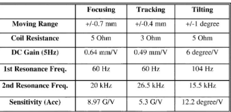
TABLE I
ACTUATOR’SCHARACTERISTICS
variation of less than 5% within the full focusing and tracking stroke.
V. EXPERIMENTALPROCEDURE
By applying the Laplace transformation on (10)–(12), the transfer functions of the system are
(10) (11) (12) Fig. 7 shows the Bode plots of the focusing, tracking, and tilting direction vibrations at the frequency response of the prototype measured by a Polytec OFV 30 sensor head and an Agilent 35670A dynamic signal analyzer. The first natural frequency of 60 Hz is very close to the theoretical value of 61 Hz. Furthermore, the present system provides a high band-width of about 20 kHz for focusing and 26 kHz for tracking, respectively. The rotary mode should not appear in the area between the first natural frequency caused by four-wires and the first high resonant frequency caused by the lens-holder, respectively. FEM analysis was used to expand the tolerance of high resonant frequencies of the lens-holder design. Since the rolling mode does not appear in the Bode plots, the operation in the servo control allows a longer smooth area. In addition, relevance to the inductance, if the phase delay at 1 kHz operates at extremely small frequencies, the stability of the overall system can be improved accordingly.
VI. CONCLUSION
The three-axial control actuator has been developed by using the traditional four-wire actuator and by adding one pair of tilting magnets. Table I presents the characteristics of the four-wire actuator. The acceleration for focusing, tracking, and tilting directions are 8.97 G/V, 5.3 G/V, and 12.2 de-gree/s /v, respectively [14]. The dimensions of the actuator are approximately 23 15 8.4 mm , as shown in Fig. 8. It is
Fig. 8. Prototype of the three-axial actuator.
significantly more compact than previous four-wire and sym-metric three-axial actuators. The tilting method of the actuator used in this paper is another innovation. It can independently compensate tilt degree associated with a torque variation of less than 5%. The proposed technique provides an efficient method to control the tilt margin in the advanced memory systems.
REFERENCES
[1] T. Tomiyama, “Objective lens moving actuator,” U.S. Patent 5 313 334, 1994.
[2] I. Kasuga, “Device for driving an objective lens,” U.S. Patent 5 541 898, 1996.
[3] M. Nagasato and I. Hoshino, “Development of two-axis actuator with small tilt angles for one-piece optical heads,” Jpn. J. Appl. Phys., vol. 35, pp. 392–397, 1996.
[4] I.-H. Choi et al., “Compact disk/digital video disk (CD/DVD)-com-patible optical pickup actuator for high density and high speed,” Jpn.
J. Appl. Phys., vol. 37, p. 2189, 1998.
[5] D.-J. Lee, M.-G. Song, C. Kim, N.-C. Park, Y.-P. Park, N. Onagi, and G. Akanuma, “Improvement of dynamic characteristics for symmetric-type slim optical pickup actuator by changing coil shape,” IEEE Trans.
Magn., vol. 43, no. 2, pp. 808–810, Feb. 2007.
[6] M. Mohri, “Object lens driving device,” U.S. Patent 6 134 058, 2000. [7] D.-J. Lee et al., “Development of three-axis actuator for HD-DVD,”
IEEE Trans. Magn., vol. 41, no. 2, pp. 1050–1052, Feb. 2005.
[8] W. Kim, J. E. Kim, and Y. Y. Kim, “Two-phase optimization for the design of multiple coils,” IEEE Trans. Magn., vol. 41, no. 10, pp. 4093–4095, Oct. 2005.
[9] M. Bartsch and T. Weiland, “2D and 3D calculation of forces,” IEEE
Trans. Magn., vol. 30, no. 5, pp. 3467–3470, Sep. 1994.
[10] K. Takeuchi et al., “Fast actuator modeling by finite element method,”
IEEE Trans. Magn., vol. 30, no. 6, pp. 4284–4286, Nov. 1994.
[11] P. D. Barba and A. Savini, “Mixed finite elements for the simulation of fields and forces in electromagnetic devices,” IEEE Trans. Magn., vol. 34, no. 5, pp. 3572–3575, Sep. 1998.
[12] C.-W. Chan et al., “The design of actuator for 3 axis,” Chin. Assoc.
Magn. Technol., vol. 25, p. 14, Jul. 2000.
[13] L.-D. Wei et al., “The design of actuator for 3 axis,” Chin. Assoc. Magn.
Technol., vol. 25, p. 33, Jul. 2000.
[14] I.-H. Choi et al., “Concentrated anisotropic magnetization for high sen-sitivity of optical pickup actuator,” IEEE Trans. Magn., vol. 35, no. 3, pp. 1861–1864, May 1999.
Manuscript received July 24, 2006; revised August 13, 2007. Corresponding author: Y. S. Lan (e-mail: [email protected]).