Flyback Converter using Single-Capacitor Snubber for Auto-tuning Fan Speed System
*
G.-K. Chang, S.-Y. Tseng, P.-F. Chen, S.-T. Peng and
*S.-Y. Fan
*Linear Motor Research Laboratory Department of Electrical Engineering
Wufeng Institute of Technology Ming-Hsiung, Chia-Yi, Taiwan E-mail: [email protected]
TEL: 886-5-2267125
GreenPower Evolution Applied Research Lab (G-PEARL) Department of Electrical Engineering
Chang Gung University Kwei-Shan, Tao-Yuan, Taiwan, R.O.C
E-mail: [email protected] Tel: 886-3-2118800; Fax: 886-3-2118026 Abstract -- This paper presents flyback converter combined
with single-capacitor turn-off snubber for auto-tuning fan rotational speed system. The proposed system can automatically regulate rotational speed of fan, depending on temperature in the chassis of the equipments. Its control algorithm is to regulate output voltage of the proposed converter. With this approach, the wear and tear of the bearing of fan can be reduced and the circuit structure compared with the conventional two stage driving circuit can be simplified. Therefore, the proposed system can raise conversion efficiency, reduce component count, weight and size. Moreover, in order to further increase conversion efficiency of the proposed system, a single-capacitor turn-off snubber is adopted to reduce switching loss at turn off transition, Finally, a prototype under output voltage varied from 5V~12V and maximum output power of 200W has been implemented to prove the feasibility of the proposed auto-tuning fan rotational speed system.
Index Terms-- flyback converter, single-capacitor snubber I. INTRODUCTION
With the advances of technology, electronic product is making revolution, both in market and in the product itself.
To meet the rigid requirement of the comsumers, lighter, thinner, shorter, and smaller have been the tendency to design and develop electronic products. However, the decrease in the dimension of the products results in drastic increase in the heat flux, and as a consequence, degrades the overall function. The approaches to remove the high heat to maintain the stability and reliability of the products, have become a key concern and received much attention. Due to its effective heat emission capability and low manufacturing cost, the forced-air cooling technique has been and will continuously be the common active design approach to remove heat from electronic products. The forced air cooling technique usually involves the combination of the fan and heat sink. This study focuses on enhancing performance of the fan driving system.
A brushless DC motor is widely used in the forced-air cooling system. The torque of this motor type is proportional to the current. It appeared that the motor wasted a lot of energy working with full speed. On-Off control was applied for energy-saving concern. It turns on and off the motor according to the feedback signal of the temperature sensor.
The frequent start of the fan brings acoustic noise, and owing to the high torque at start-up, it speeds up the wear and tear of
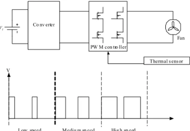
the bearing. Regulating fan speed according to the temperature inside an enclosure is the most effective method utilized to cool electronic products. In the past, variable speed was obtained with a rheostat or potentiometer in series with the motor to regulate the main current. These systems had the disadvantage of dissipating a lot of power. The yield was very low. The metal-oxide-semiconductor field-effect transistor (MOSFET) became a necessity to adapt the motor speed to real needs but without losses. Chopping the supply controls the mean voltage applied to the motor and, hence, its speed. The commonly used control technique is Pulse-Width- Modulation (PWM) where the average DC current is proportional to the duty cycle. The technique has three merits, decreasing energy consumption, reducing acoustic noise, and providing wider operational bandwidth.
Fig. 1 shows a typical connection diagram implementing PWM to a fan. A converter supply a DC bus power to the PWM inverter block, and a PWM controller will modulate the DC power to produce signal to the fan that will vary the width. An 70% duty cycle indicates that the fan is “on” 70%
of the time and “off” 30% of the time. Intuitively, a high duty cycle produces high speed and a low duty cycle will produce idle speed. To maintain the DC bus power, the DC line requires a bulk capacitor. This two-stage architecture in Fig.
1 makes the elements and volume relatively more. Also, its
integrated efficiency is lower.
Co nv erter
PW M con tro ller
Fan Vi
V
Low speed Mediu m sp eed Hig h sp eed
Thermal s ensor
Fig. 1. Conventional PWM driven fan system
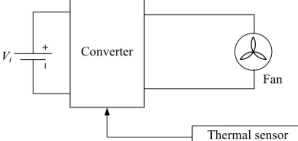
PEDS2009To improve these, this article proposes a flyback type converter that will produce directly variable voltage level to the fan to drive it at appropriate speed. The block diagram of this architecture is shown in Fig. 2. As can be seen, it is a one-stage architecture.
Converter
Fan
Thermal sensor Vi
Fig. 2. Flyback-converter-driven fan system II. SOFT-SWITCHING HIGH FREQUENCY CONVERTER Isolated PWM converters are widely used as step-up or step-down dc/dc converters. To reduce size and weight of the converters, there is a trend to operate them at high switching frequencies. However, as the switching frequency increases, switching loss, noise and stress associated with turn-on and turn-off transitions also increase. To alleviate the problem, soft-switching PWM is adopted. Two groups of soft- switching technique are normally used: passive soft- switching and active soft-switching. The passive one use only passive components to achieve zero-current transition at turn- off[2-5]. The active one incorporate passive components and auxiliary active switches to achieve soft-switching commutation[6, 7], which increases cost significantly. Thus, a converter with passive soft-switching feature is more attractive to low power applications.
In a single passive soft-switching converter, such as flyback converter, it is equipped with a lossless turn-off snuber to reduce turn-off loss and is operated at the boundary of discontinuous conduction mode (DCM) and continuous conduction mode (CCM) to reduce turn-on loss. Due to this operation, inductor current will swing over a wide range. To reduce ripple current and increase power level, two flyback converters operated with an interleaving fashion are usually adopted. Although the two converter can achieve soft- switching features, their component count and cost increase as well. A soft-switching isolated interleaving converter with a single-capacitor turn-off snubber is proposed which releases the above drawbacks.
III. DERIVATION OF THE PROPOSED CONVERTER Two flyback converters with lossless turn-off snubbers form the basic topology of the proposed interleaving converter, as shown in Fig. 3(a). In the figure, two passive soft-switching cells enclosed in the dashed line are formed with only passive switches and reactive elements. To simplify and integrate two turn-off snubbers, voltages Vcs12 and
22
Vcs of snubber capacitors Cs12 and Cs22 can be replaced by output voltage V to become dc voltage o sources. Thus, diodes Ds13 and Ds23 can be removed and they do not need to discharge the charges stored in the voltage sources Vcs12 and Vcs22, as shown in Fig. 3(b).
When Vcs12 and Vcs22 are equal to V , nodes B and D o can be considered as common node G, and the circuit can further simplified as shown in Fig. 3(c). Based on the operational principle of the interleaving forward converters and turn-off snubber, operational states of diode D (or 11 D ), is the same as diode 21 Ds21 (or Ds11) except that turn-off snubber is operated within resonant time duration.
Since the resonant time duration is much shorter than the switching period of the derived converters, when nodes E and C (or F and A ) are connected as the same node, it will not affect the operational states of the derived interleaving forward converters, as shown in Fig. 3(d). From Fig. 3(d), it can be seen that when the interleaving flyback converters are operated in DCM or CCM, diodes Ds22 and Ds12 are in cutoff status, therefore, diode Ds22 and inductor Ls21, as well as diode Ds12 and inductor Ls11, can all be removed.
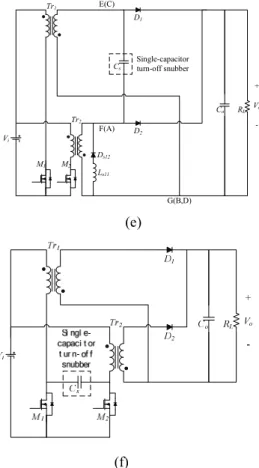
Diode D and 11 Ds21 (or D and 21 Ds11) are connected in parallel, so the diodes can be combined as one diode D 1 (or D ). While, capacitors 2 Cs12 and Cs22 are connected in parallel, they can be combined as one capacitor C , as s shown in Fig. 3(e). It can be seen, the derived flyback converter requires only a resonant capacitor C to function s as a lossless turn-off snubber, reducing switching losses and component counts.
In Fig. 3(e), since voltages across windings of transformers Tr1 and Tr2 satisfy the volt-second balance, and the average voltage across snubber capacitor Cs is equal to 0 during one switching cycle, snubber capacitor Cs can be relocated from secondary side of transformers Tr1 and Tr2, in which it is respectively connected in between of secondary side across no dot terminals, to primary side across no dot terminals, as shown in Fig. 3(f). They will not affect the original functions of the derived flyback converters and single-capacitor snubber [8].
The proposed auto-tuning fan speed system based on the interleaving flyback converter using single-capacitor snubber is shown in Fig. 4. Two feedback signals, Vf , derived from Vo, and VT, from temperature sensor, are fed into a PWM IC, the IC then calculate to determine the duty cycle. Two opposite PWM signals are produced to control the power transistor switches M1 and M2 of the converter which in turn regulates the output voltage to its demanded level.
PEDS2009
(a)
(b)
Vi
D11
Tr1
D21
Tr2
M1 M2
Ds21
Ds22
Cs21
Ls21
Ds11
Ds12
Cs11
Ls11
A
C E
F
G(B,D) RL
Co
+ Vo
- Lossless
turn-off snubber
Lossless turn-off snubber
(c)
Vi
D11
RL
Tr1
D21
Tr2
Co
M1 M2
Ds11
Ds12
Cs11
Ls11
Ds21
Ds22
Cs21
Ls21
E(C)
F(A)
G(B,D)
+ Vo
-
(d)
Vi
D1
RL
Tr1
D2
Tr2
Co
M1 M2
Ds12
Ls11
Cs
E(C)
F(A)
G(B,D)
+ Vo
- Single-capacitor
turn-off snubber
(e)
(f)
Fig. 3. Illustration of interleaving flyback converters with a single-capacitor turn-off snubber derived from
those with two lossless turn-off snubber
Fig.4. Proposed interleaving flyback converter using single-capacitor snubber for auto-tuning fan speed system
IV. DESIGN PROCEDURE OF THE PROPOSED CONVERTER To ensure that the proposed soft-switching converter can work as expected, design procedures are outline as follows.
A. Duty Ratio D
To determine duty ratio D , we must first attain input to PEDS2009
output voltage transfer ratio M . Since capacitor snubber C only helps switches s M and 1 M to achieve soft-2 switching feature, they do not affect transfer ratio M . According to volt-second balance theorem, the volt-second balance relationship of magnetizing inductor Lm1, (or Lm2) of transformer T (or r1 T ) can be given by r2
0 T D N 1 DT V
Vi s−( o)( − ) s = (1) Where N(=n12/n22=n22/n21) is turns ratio of transformer Tr1 or Tr2, Vi and Vo are input and output voltage. Form (1), it can be found that transfer ratio M can be expressed as
D 1 M ND
= − (2) For the flyback converters with a single-capacitor snubber to work in interleaving manner, the duty ratio of the power transistor switches M11 and M21 is not greater than 0.5.
According to (2), a larger duty ratio D corresponds to a smaller transformer turns ratio N , which results in a lower current stress imposed on switches M11 and M21, as well as lower voltage stress imposed on free wheeling diodes D1 and D2. However, in order to accommodate variations of loads, line voltages, and component values, it is better to select a nominal operating range as D=0.35~0.4.
B. Trnasformer Tr1 or Tr2
Once the duty is selected, the turns ratio of transformer
1
Tr or Tr2 can be determined using (2), which yield.
i o
DV V D
N =(1− ) (3)
By applying the Faraday's law, primary turns N11 (or N21) of transformer Tr1 (or Tr2) can be given by
B A
T N DV
N
c s 21 i
11= = Δ (4) Where Ac is the effective cross-section area of the transformer core and B
Δ
is working flux density.According to (3) and (4), secondary turns N12 (
=
N22) can be determined.For the proposed flyback converters, the magnetizing inductance of Lm1 and Lm2 are determined by taking into account the current down slope while corresponds to the off- time of switch M1 and M2, and the inductance must be large enough to maintain CCM operation. The inductance of
1
Lm (or Lm2) must satisfy the following inequality:
(max)
) (
1 Lm
s 1 o
m N I
T D 1 L V
Δ
≥ −
(5)Where ΔILm1(max) is the maximum current of magnetizing inductance. When we set a maximum current ripple, the minimum magnetizing inductance can be determined.
C. Output Filter Capacitor
The output filter capacitor Co is primarily designed for reducing ripple voltage. For aluminum electrolytic capacitor, since their equivalent series resistances are very low, the ripple voltage across the equivalent series resistance can be neglected. Thus, the ripple voltage across output capacitor
Co is determined as follows:
s o D
o
rco co I DT
C 2
1 C 2
V = ΔQ = (max)
Δ
Where Io(max) is the maximum value of output current.
D. Snubber Capacitor Cs
In the proposed converters, capacitor Cs resonates with magnetizing inductor Lm1 and Lm2 to smooth out switch turn-off transition. The energy stored in Cs can be determined as
o2 s
cs C V
2
W
=
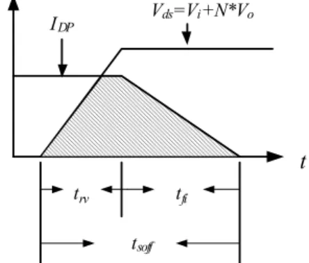
1 (6) During turn-off transition, another two time intervals, trv and tfi, are involved, as shown in Fig. 5. The turn-off loss Wsoff therefore can be approximated asi DP soff i
soff I
N V V 2
W
=
t( + ) (7)
Where
tsoff=
trv+
tfiand
IDPis the current through the switch.
To completely eliminate the switch turn-off loss, the energy stored in capacitor
C must be at least equal to the st
trv tfi tsoff
Vds=Vi+N*Vo
IDP
Fig. 5. Conceptual current and voltage waveform of active switch during turn-off transition
PEDS2009
tur-off loss
Wsoff. Thus the capacitance of
C can be sdetermined as
o DP s soff I
NDV C ≥ t
V. M
EASUREDR
ESULTSTo verify the performance of the proposed interleaved flyback converter, a prototype with the following specifications was implemented.
Input voltage
Vi: DC 380V Switching frequency
fs: 50kHz
Output voltage
Vo: 4 ~12V (0 ~ 100% of full speed of fan)
Maximum output current
Io(max): 16.7A Maximum output power
Po(max): 20 W
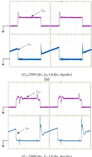
Measured voltage
VDSand current
IDSwaveforms of switch
M1in the interleaved flyback converter under full load condition is shown in Fig. 6. Fig. 6(a) shows those waveforms of the interleaved flyback converter with hard- switching circuit, while Fig. 6(b) shows those waveforms of the converter with the proposed single-capacitor snubber. It can be seen that with the proposed snubber, the switch can operate with zero-voltage transition at turn-off transition.
Fig. 7 illustrates efficiency comparison between the interleaved flyback converter with hard-switching circuit and with the proposed single-capacitor snubber. It can be observed that the efficiency of the topology with the proposed single-capacitor snubber is higher than that with hard-switching circuit at loading condition higher than 30%.
Its efficiency is 88% under full load condition. While below 30% loading, the efficiency of the two are almost the same.
VI. C
ONCLUSIONIn this paper, an interleaving flyback converter with single-capacitor turn-off snubber to smooth out switch turn- off transition has been derived. Their operational principle, steady-state analysis and design consideration have also been described in detail. This paper further applies the converter to auto-tuning fan rotational speed system to simplify the conventional two-stage architecture to one-stage. A 200W, 12V/16.67A experimental prototype has been built and tested. The results show that, by the use of a cheap single- capacitor snubber, the interleaving flyback converter can effectively reduce the rising rate of
VDSover the switch power transistor. Furthermore, since the switches are operated in zero-voltage transition, the switching losses are reduced and the overall efficiency is increased by as much as 20%.
(VDS:250V/div, IDS:1A/div, 4μs/div)
(a)
(VDS:250V/div, IDS:1A/div, 4μs/div)
Fig.6. Measured voltage
VDS(b) and current
IDSwaveforms of switch
M1in the interleaved flyback converter (a) with hard-switching circuit and (b) with the proposed single-capacitor snubber.
Fig. 7. Efficiency comparison between the interleaved flyback converter with hard-switching circuit and with the proposed single-capacitor snubber from light load to heavy load
PEDS2009
R
EFERENCES[1] Arredondo, A.; Roy, P.; Wofford, E.; “Implementing PWM fan speed control within a computer chassis power supply,” Proceedings of the Applied Power Electronics Conference and Exposition, 2005, vol. 1, 6- 10 March 2005, pp.148–151.
[2] Smith, K., and Smedley, K., "Lossless passive soft switching methods for inverters and amplifiers," Proceedings of the Power Electronics Specialists Conference, 1997, pp.1431-1439.
[3] Tseng, C-J., and Chen, C-L., "Passive lossless snubbers for dc/dc converters," Proceedings of the Applied Power Electronics Conference, 1998, pp. 1049-1054.
[4] Yaakov, S-B., and Ivensky, G., "Passive lossless snubbers for high frequency PWM converters," Tutorial of IEEE Power Electronics Specialists Conference, 1997.
[5] Munoz, C., "Study of a new passive lossless turn-off snubber," in Proceedings of the CIEP Conference, 1998, pp.147-152.
[6] Watson, R., Hua, G., and Lee, F-C., "Characterization of an active clamp flyback topology for power factor correction applications," IEEE Transactions on Power Electronics, vol. 11, Jan. 1996, pp.191-198.
[7] Duarte, C., and Barbi, I., "A family of ZVS-PWM active-clamping dc- to-dc converters: synthesis, analysis, design, and experimentation,"
IEEE Transactions on Circuits and Systems-I: Fundamental Theory and Applications, vol. 44, Aug. 1997, pp.698-704.
[8] S.-Y. Tseng, Y.-K. Chen, and Y.-W. Chang, “A Systematic Approach to Developing Isolated Interleaving Converters with a Single-Capacitor Turn-Off Snubber,” Proceedings of the Power Electronics Specialists Conference, 2006, 18-22 June, 2006. pp. 1–7.
PEDS2009