Chien-Cheng Liua)and Jow-Lay Huangb)
Department of Material Science and Engineering, National Cheng-Kung University, Tainan, Taiwan 701, Republic of China
(Received 9 January 2003; accepted 21 October 2003)
The friction and wear behavior of Si3N4-based composites against AISI-52100 steel were investigated in the ball-on-disk mode in a nonlubrication reciprocation motion. It has been found that under the conditions used, all the ceramic components exhibited rather low friction and wear coefficients. For monolithic silicon nitride materials, high friction coefficients between 0.6 and 0.7 and wear coefficients between 1.63 × 10⁻⁸ and 1.389 × 10⁻⁶mm3/N · m were measured. The contact load was varied from 100 to 300 N. By adding titanium nitride, the friction coefficients were reduced to a value between 0.4 and 0.5 and wear coefficients between 1.09 × 10⁻⁸and 0.32 × 10⁻⁶mm3/ N · m at room temperature. All materials and worn surfaces as well as wear debris were investigated by means of scanning electron microscopy, energy dispersive spectroscopy, x-ray diffraction, and transmission electron microscopy (TEM) before or after the tribological tests. The TEM micrographs of wear track revealed plastic deformation through twins and cracking along grain boundary which play an important role in the fracture mechanism.
I. INTRODUCTION
Silicon nitride ceramic materials have shown promis-ing physical properties such as high strength at elevated temperature, low thermal expansion coefficient, low den-sity, and superior chemical stability in corrosive environ-ments. They have widely been used in various engineer-ing applications includengineer-ing cuttengineer-ing tools, drawengineer-ing dies, roller bearing, heat exchangers, and automotive engine parts.1–6However, there are major obstacles to the wide-spread use of ceramics including their low mechanical reliability due to inherent brittleness and the difficulties involved in shaping and machining. One approach to improving the mechanical properties of brittle materials in general is through composite strengthening tech-niques, such as fiber, whisker, or particulate reinforced ceramics. The primary toughening mechanisms of par-ticulate-reinforced ceramics have been attributed to in-teraction between the crack front and particulates, crack deflection, crack bridging, residual stress, and grain size.7–12
Among various types of silicon nitride composites, an addition of TiN particles into silicon nitride has proved successful in increasing fracture toughness with little sacrifice in strength.13In addition, for TiN content higher
than 30 vol%, the electrical resistivity of the composites is less than 10−3 ⍀·cm so that electrical discharge ma-chining (EDM) is feasible to produce complex-shaped parts.14,15
Moreover, TiN itself is appreciated as the sec-ond phase material having a low friction coefficient to-gether with high hardness. It is often chosen as a surface coating to improve the tribological characteristics of materials.
Much study has been carried out on the friction and wear behavior of ceramic against metal and ceramic against ceramic couples in sliding contact. Most of these studies focused on the effect of environment including temperature, humidity, and lubricant on the sliding wear behavior of Si3N4 against a variety of counter-face ma-terials.16–18Imada et al.19have reported that the Si3N4– TiN composites were investigated under dry oscillating sliding conditions and showed that the wear coefficient of Si3N4was distinctly reduced by the addition of TiN. Tribological behavior of ceramic materials is strongly dependent on contact load, sliding speed, temperature, humidity, contact geometric configuration, lubricant, as well as microstructure of materials.20–23
Titanium nitride (TiN) particles have been added to silicon nitride (Si3N4) to form composites. Benefits as-sociated with the addition of the TiN to Si3N4 include higher fracture toughness and lower electrical resistivity. In addition, a significant decrease in the wear rate and friction coefficient of the Si3N4–TiN composites is expected to result from the incorporation of TiN. The
a)
e-mail: [email protected]
b)
microstructure of silicon nitride composite materials is governed by the amount of secondary phase. This work investigated the tribological characterization of silicon nitride–based composites with secondary phase TiN ad-dition and examines the effects of different load under unlubricated reciprocating sliding against AISI-52100 steel ball bearing. The coefficients of friction and wear rate were measured. Scanning electron microscopy (SEM), transmission electron microscopy (TEM), and energy dispersive spectroscopy (EDS) were used to de-termine the nature of the friction and wear processes.
II. EXPERIMENTAL A. Materials fabrication
The Si3N4 (UBE SN-E10) powder was mixed with 2 wt% Al2O3 (16SG, Alcoa, 0.5 m) and 6 wt%Y2O3 (5603, Molycorp, Brea, CA, 1.8m) in a polyurethane bottle with high-purity silicon nitride balls and ethanol for 24 h. The ratio of ball, charge, and vehicle was 6:1:5 in weight. The TiN of 3.5m sizes (H.C. Stark, Goslar, Germany, 20% and 40% of total volume) were dispersed and added to the Si3N4 slurry, milled for a further 2 h, then dried in a rotary evaporator. Dried agglomerates were ground with a mortar and pestle to pulverize ag-gregates and were passed through a 100 mesh sieve. Samples were hot-pressed at 1850 °C for 1 h under a uniaxial pressure of 24.5 MPa and nitrogen flow in a graphite furnace (Fuji Dempa High Multi 5000, Japan). Some samples were plasma etched (Plasma-Them Inc., Helix Sputter, Taiwan, Series 70) in mixtures of CF4and O2with a gas flow ratio of 93:7 in rf sputtering system for 2 min and then ultrasonically cleaned prior to the examination by SEM. After each test, microstructural modifications and wear volume in the track were ob-served by SEM coupled with energy dispersive analysis of x-rays. TEM foil preparation was performed by stan-dard techniques that include diamond cutting, ultrasound drilling, mechanical grinding, dimpling, argon ion thin-ning to perforation from the side opposite the wear scar, and a light carbon coating. The composite has different grain sizes and mechanical properties, respectively, as described in the previous report.13
B. Wear test
Friction and wear tests were performed on a ball-on-disk, point contact wear mode under nonlubrication con-dition. All wear tests were conducted with a reciprocat-ing machine (SRV, Optimal, Bielefeld, Germany) con-sisting of a reciprocating ball sliding on a stationary disk as shown schematically in Fig. 1. The ball is mounted in the upper holder, which only allows parallel movement in the sliding direction. The specimen is fixed in the
lower holder, which is supported by two steel blades. The friction force was continuously measured by the force transducers. The friction force, induced between steel ball and disk, was measured by an analog-to-digital con-verter and saved in a personal computer. The experimen-tal conditions were as follows.
(i) The flats were circular disks, either monolithic Si3N4 or TiN–Si3N4 composites with a diameter of 20 mm. The thickness of the flat disk was 6 mm.
(ii) The ball was a 10-mm-diameter AISI-52100 steel ball bearing (C, 0.95–1.1%; Si, 0.15–0.35%; Cr, 1.3– 1.6%; Mn, <0.5%) with a hardness of 7.6 GPa.
(iii) Tribological testing was performed under a nor-mal contact load of 100, 200, and 300 N and a sliding distance of 120 m at 50 Hz (sliding velocity of 0.1 m · s−1) for 20 min. All the tests were conducted at room tem-perature with a relative humidity of 50–55%.
All specimens were ground in parallel with 600 dia-mond grit. The sliding surface was finished by grinding and polishing to Ra ⳱ 0.1 m with 6- and 0.25-m diamond paste. Before testing, all samples were ultra-sonically cleaned with ethyl alcohol and subsequently with de-ionized water and then dried under nitrogen flow. C. Test characteristics
After test, debris were collected and stored in a vacuum desiccator for further analysis. The worn sur-faces were examined by scanning electron microcopy, and their topography were measured by profilometry (Kosaka, surfcorder SE-30H, Honshu, Japan). The wear debris was examined by SEM, TEM, and x-ray diffrac-tion (XRD) to determine phases. Tribological factors in-clude the friction coefficient and the wear coefficient (W),
W = VⲐLD 共mm3⭈ N−1⭈ m−1) ,
with V (mm3) the wear volume, L (N) the normal force, and D (mm) the sliding distance.24 Estimation of the
FIG. 1. A schematic representation of the ball-on-disk wear testing apparatus.
wear volume on the track of the ceramic test specimens was done by measurement using profilometry and mi-croscope image of the width and length of the wear scar on each sample after the tests. The mechanical properties of the monolithic Si3N4and TiN–Si3N4 composites are given in Table I.13
III. RESULTS AND DISCUSSION A. Microstructures
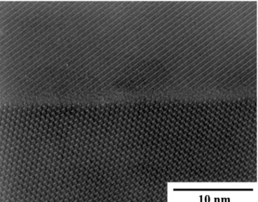
The fabrication of Si3N4ceramics normally requires a sintering additive because of the characteristics of the covalent bond. In most cases, it is necessary for Si3N4to be processed by liquid-phase sintering, which enhances the mass transport and a solution reprecipitation mecha-nism of Si3N4, to obtain fully dense bodies. Figure 2 shows the lattice image between Si3N4 grains, which exerts a very thin layer of amorphous phase. There was an amorphous phase at grain boundary of Si3N4grains. The amorphous phase was due to the sintering aids Al2O3 and Y2O3added to the starting material. Figure 3 reveals that titanium nitride particles are relatively uniformly distributed in the silicon nitride matrix. The white areas represent TiN, whereas gray regions indicate Si3N4. The shape and size of each silicon nitride grain and surround-ing TiN particles were clearly seen after plasma etchsurround-ing.
The grain size of -Si3N4 decreased slightly with in-creasing the amount of TiN secondary phase. The me-chanical properties of these materials were described earlier.13
B. Friction and wear coefficients
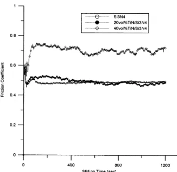
The friction coefficient of monolithic Si3N4and TiN– Si3N4composites against AISI -52100 steel ball pairs is plotted during a continuous test up to a slide distance of 120 m at velocity of 0.1 m·s−1for 20 min (Fig. 4). One observes that the friction coefficient of monolithic Si3N4 usually starts at a relatively low value and reaches a stable value between 0.7 and 0.75 after 50 s of sliding. The friction behavior of Si3N4is uneven. In contrast, the friction coefficient of the TiN–Si3N4composites against AISI-52100 pairs rises up to 0.62 at a very short time and then sharply drops to 0.45 followed by a steady value of about 0.5, a lower friction coefficient. The TiN–Si3N4 composites exhibited a steady friction coefficient that was lower than that of monolithic Si3N4 in the recipro-cating sliding wear test.
Figure 5 shows the variation in friction coefficient as a function of normal load. It can be observed that the friction coefficient has a trend of increase with the in-crease in load. However, the friction coefficient for the
TABLE I. Mechanical and physical properties of the monolithic Si3N4and TiN–Si3N4composites.
Sample
Relative
density (%) Resistivity (⍀ ⭈ cm) Hv (GPa)
Fracture toughness (MPa m1/2) Flexural strength (MPa) Si3N4 98.7 4.2 × 10¹³ 13.9 ± 0.6 5.4 ± 0.2 822 ± 55 20 vol% TiN–Si3N4 97.45 7 × 10⁹ 13.2 ± 0.4 6.5 ± 0.4 663 ± 51 40 vol% TiN–Si3N4 97.35 1.25 × 10⁻³ 12.4 ± 0.4 6.2 ± 0.35 521 ± 30
FIG. 2. TEM image of high-resolution electron microscopy images of amorphous grain boundary films in-Si3N4/-Si3N4.
FIG. 3. Scanning electron micrograph of polished and plasma etched surfaces of 20 vol% TiN–Si3N4composites sintered at 1850 °C under
monolithic silicon nitride is higher than those of TiN– Si3N4composites. Estimation of the volume of abraded material on the track of the ceramic test specimens was done by measuring the width and length on a microscope image of the wear scar. Depth of the wear scar was determined using profilometry. A profile across the wear track showed a concave shape. Although the correlation
and measurement were undefined, it is a convenient measurement for the average wear coefficient of the specimens. In general, Si3N4and TiN–Si3N4composites exhibit a small wear coefficient of about 1.32 × 10⁻⁶
and 0.32 × 10⁻⁶
mm−3
(Nm)−1
in comparison with other ce-ramic materials.19
The wear volume of specimens of TiN–Si3N4 composites is lower than that of the speci-mens of monolithic silicon nitride for all test conditions. This suggests that high wear volume accompanies a higher friction coefficient.
Figure 6 shows the wear coefficients of three different test samples. They have similar trend, and the Si3N4has the highest wear coefficients among all materials. The wear coefficients increase with load up to a maximum at 300 N for all materials. Dong et al.25have reported that at small loads and low temperature, the tribological be-havior of silicon nitride is controlled by tribochemical reactions between the sliding surface and water vapor in the air, which forms a thin hydroxylated silicon oxide film. Presence of this film on the wear track can re-duce the friction coefficient. The wear coefficients of TiN–Si3N4 composite containing 20 and 40 vol% TiN are 0.368 × 10⁻⁶mm−3(N · m)−1and 0.32 × 10⁻⁶mm−3 (N · m)−1 under 300 N, respectively. The wear rate of TiN–Si3N4 composites is approximately four times lower than that of monolithic silicon nitride. Skopp et al.17have reported that silicon nitride composites are able to form relatively soft lubricious oxides like TiO2-x film on a hard substrate, so that a tribochemical wear mechanism dominates. The results also showed that the wear coefficient of Si3N4 was distinctly reduced by
FIG. 5. Effect of normal loads on the friction coefficients of silicon nitride–based composites against AISI-52100 steel ball pairs in dry sliding test.
FIG. 4. Friction coefficient versus sliding time of silicon nitride– based composites against AISI-52100 steel ball pairs in dry sliding tests.
FIG. 6. Effect of normal loads on the wear coefficients of silicon nitride–based composites against AISI-52100 steel ball pairs in dry sliding test.
the addition of TiN. Additionally, the mechanical prop-erties of the monolithic Si3N4and TiN–Si3N4composites were measured and are listed in Table I. Results indicated the fracture toughness was increased and the flexure strength was slightly decreased as TiN content was raised. Friction coefficient and wear rate of TiN–Si3N4 composites in nonlubrication contact are probably related to the fracture toughness, flexure strength, and TiN content.
C. Wear surface and debris examination
To further study the interactions between silicon nitride–based composites and steel ball under wear con-ditions and to understand the mechanism leading to the effect on sliding wear, the wear particles were examined after tests. The sizes of wear debris particles consist of a combination of large plates (∼6 m) and much smaller particles, as shown in Fig. 7. These were almost
certainly fragments of iron from the steel ball. For all test conditions, the morphology of wear debris particles found a combination of large plates and a large quantity of smaller particles. The smaller particles (less than 1m) are frequently found clumping themselves into a large aggregate. Gomes et al.26
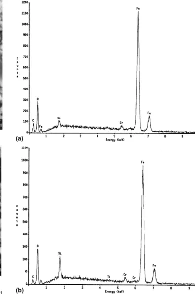
have investigated the tribological behavior of Si3N4 pins against tool steel disks at room temperature. The debris particles are mostly composed of iron and silicon. The effect of ad-herent layers of oxidized material on the ceramic surfaces is the decrease of the ceramic wear coefficient. The EDS pattern of the wear debris, shown in Fig. 8, displays the wear debris contains a lot of iron, chromium, and a small proportion of silicon elements. Thus, the wear debris produced in Si3N4, TiN-Si3N4–AISI-52100 couple con-tains lesser amounts of ceramic powder than iron. This is in agreement with the results that the ceramics show much less wear loss than AISI-52100 steel ball.
FIG. 7. Scanning electron micrograph of the debris from Si3N4-based
composites against AISI-52100 steel ball pairs dry sliding tests: (a) monolithic Si3N4, and (b) containing 40 vol% TiN–Si3N4.
Fig. 8. EDS x-ray spectra from the debris of (a) Si3N4and (b) 40 vol%
Typical photographs of wear surface of Si3N4 and TiN–Si3N4 composite are shown in Fig. 9. It can be found that the wear surface is smooth, there are no mi-crocracks on the worn surface after wear experiments in unlubricated sliding. During the sliding process, a plastic deformation of the surface layer of the wear track takes place. This plastic deformation may exist at the subsur-face cracking but not run to the sursubsur-face damage. The SEM observation of the worn surface and EDS analysis indicate the presence of a metallic layer transferred on the ceramic surface. These debris are produced mostly perpendicular to the direction of sliding and adhered on ceramic surface. This suggests that the fragments ad-hered on ceramic surface contain substantial amounts of ferrous wear debris.
D. Wear mechanism
In nonlubricated condition, the SEM micrographs of wear tracks do not reveal any indication of plastic
de-formation. The TEM investigation disclosed two plastic deformation mechanisms: deformation twins and dislo-cation pile-ups on the worn surface. Figure 10(a) shows the twin planes occurring in the Si3N4 grains while Fig. 10(b) is a typical image from the dislocation pile-ups in TiN grains. Wang et al.27
have pointed out that the surface morphologies during the wear process can result in higher asperity contact stresses. The stress at the as-perity tip contacts exceeds the plasticity limit of the ma-terial and generates dislocations and twins on the contact surface and subsurface. The accumulated dislocations and twins result in sub-micrometer-scale cracking. The deformation twins are an important mechanism of plastic deformation in hexagonal-close-packed (HCP) structure, although it is not as common as slip. When a crystal
FIG. 9. SEM micrographs showing the wear track of (a) Si3N4and
(b) 20 vol% TiN–Si3N4after dry sliding tests.
FIG. 10. Bright-field TEM image of (a) twins plane in a-Si3N4grain
and (b) dislocations pile-ups in a TiN grain under a normal contact load of 300 N dry sliding tests.
deforms plastically by twinning, there occur atomic dis-placements, which give rise to crystal bands within the grains that are twin-oriented. This stress for initiation of twinning is much larger than the stress necessary for its propagation. Deformation twinning occurs when the ap-plied stress is high due to work hardening or low tem-peratures or, in the case of HCP structure, when the resolved shear stress on the basal plane is low.28,29
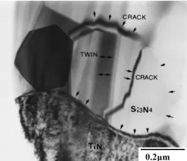
Figure 11 shows that it is possible to have cracks propagate between silicon nitride and titanium nitride under the compression load. The intense deformation twins activity were found in-Si3N4grain, which even-tually leads to their transgranular cleavage. The force transmitted from one -Si3N4 grain to other titanium nitride grain, originating from the contact region, has resulted in microcrack. The crack path was indicated by arrowheads as shown in Fig. 11. In this process, many dislocations were generated in the TiN grains in com-parison with the-Si3N4 grains. Thus, the interface be-tween-Si3N4and titanium nitride grains are a potential site for microcrack nucleation within the material under a normal contact load of 300 N dry sliding tests. In the
composite with large difference in thermal expansion between the secondary phase TiN and Si3N4 matrix, the toughening mechanism was reported to be due to the energy absorption caused by microcracking.30
Dynamic compression fatigue in silicon nitride was studied by Sharma et al.31
Their results indicated that the mecha-nism of crack propagation preferred to grow along the interface between silicon nitride grains and the amor-phous grain-boundary phase. Fracture mechanisms for silicon nitride under 1400–1520 °C creep tests were studied by Pezzotti et al.32The slow crack growth from crack profile propagated at 1400 °C. The fracture ap-pears to propagate completely along the glassy SiO2 in-tergranular phase in a completely “brittle” fashion. On the other hand, ceramic-hardened steel couples were carried out under dry sliding conditions at room temp-erature. Very large local stresses on the ceramic sur-face produced by asperity contact cause sursur-face or sub-surface cracking on a very fine scale which also results in plastic deformation and groove as well as some microfracture.33
An increased degree of crack deflection at the particle– matrix interface is observed with TiN-reinforced Si3N4 composites. Under repeated loading, subsurface damage could be substantial, leading to occurrence of transgranu-lar cleavage. A schematic of the interaction between propagation crack and deformation twins is shown in Fig. 12. Wear of Si3N4can be attributed to deformation twins activity and subsequent cracking along the grain-boundary across -Si3N4 grain transgranular cleavage. Previous studies18,34
on the tribological performance of Si3N4-based composites have shown that the friction co-efficient and wear behavior are complex and could be controlled by several different mechanisms, such as tri-bochemical reactions, plastic deformation, microfracture, oxidation, and adhesive wear. Many factors, such as atmospheric humidity, temperature, speed, load, and mi-crostructural feature, strongly influence the wear mecha-nisms. The TiN–Si3N4 composites against AISI-52100 steel ball bearing pairs during the wear process can result in higher asperity contact stresses on the ceramic surface. These observations confirm that the primary deformation mechanism of TiN–Si3N4composites consists of micro-cracking and deformation twins.
FIG. 11. Bright-field TEM image of twins plane in a-Si3N4grain
and crack along grain boundaries under a normal contact load of 300 N dry sliding tests.
IV. CONCLUSIONS
The TiN–Si3N4composites prepared by incorporating titanium nitride TiN particles into silicon nitride Si3N4 exhibit some benefits associated with the TiN addition such as higher fracture toughness and lower electrical resistivity. A significant decrease in the wear and friction coefficient of the TiN–Si3N4 composites was observed and thought to result from the incorporation of TiN into Si3N4. The following conclusions can be drawn from the results obtained in this investigation.
(1) Friction and wear tests were performed on a ball-on-disk under nonlubrication condition in the point con-tact wear mode. It was found that the addition of TiN into Si3N4enhanced the wear resistance of the composites.
(2) The friction coefficient of Si3N4-based composites against AISI-52100 steel ball was reduced by 0.2 from 0.7 to 0.5 when filled with 20 vol% TiN.
(3) The TEM investigations on the worn surface of TiN–Si3N4 composites revealed plastic deformation leading to deformation twins and dislocation pile-ups. Twinning occurs in Si3N4grains and dislocation pile-ups inside the TiN grains.
(4) Wear can be attributed to deformation twins ac-tivity and subsequent cracking along the grain-boundary across-Si3N4 grain leading to transgranular cleavage. ACKNOWLEDGMENT
The authors would like to thank the National Science Council of Taiwan, Republic of China, for its financial support under Contract No. NSC89-2216-E-006-034. REFERENCES
1. H.J. Kleebe, G. Pezzotti, and G. Ziegler, J. Am. Ceram. Soc. 82, 1857 (1999).
2. W.H. Lee and H.E. Kim, J. Am. Ceram. Soc. 80, 2737 (1997). 3. H. Park and H.E. Kim, J. Am. Ceram. Soc. 80, 750 (1997). 4. J.A. Schneider and A.K. Mukherjee, J. Am. Ceram. Soc. 82, 761
(1999).
5. S.Y. Lee, J. Am. Ceram. Soc. 81, 1262 (1998).
6. H. Takahashi, N. Shinohara, K. Uematsu, and T. Junichiro, J. Am. Ceram. Soc. 79, 843 (1996).
7. Y.U. Gogotsi and G. Grathwohl, J. Mater. Sci. 28, 4279 (1993). 8. B.Y. Shew and J.L. Huang, Mater. Sci. Eng. A 159, 127 (1992). 9. H.J. Choi, K.S. Cho, and J.G. Lee, J. Am. Ceram. Soc. 80, 2681
(1997).
10. S.K. Lee, K.S. Lee, B.R. Lawn, and D.K. Kim, J. Am. Ceram. Soc. 81, 2061 (1998).
11. K.T. Faber and A.G. Evans, Acta. Metall. 31, 565 (1983). 12. A.G. Evans and E.A. Charles, J. Am. Ceram. Soc. 59, 371 (1976). 13. C.C. Liu and J.L. Huang, Br. Ceram. Trans. 99, 149 (2000). 14. M. Ramulu, Adv. Ceram. Mater. 3, 324 (1988).
15. Z.S. Rak and J. Czechowski, J. Eur. Ceram. Soc. 18, 373 (1998). 16. T.H.C. Childs and A. Mimaroglu, Wear 162–164, 890 (1993). 17. A. Skopp, M. Woydt, and K.H. Habig, Wear 181–183, 571
(1995).
18. U. Effner and M. Woydt, Wear 216, 123 (1998).
19. Y. Imada, K. Kanamura, F. Honda, and K. Nakajima, J. Tribol.
114,230 (1992).
20. A. Ravikiran and B.N.P. Bai, J. Am. Ceram. Soc. 78, 3025 (1995). 21. J. Vizintin, M. Kalin, S. Novak, G. Drazic, L.K. Ives, and
M.B. Peterson, Wear 192, 11 (1996).
22. C.P. Dogan and J.A. Hawk, Wear 250, 256 (2001).
23. S. Novak, G. Drazic, M. Kalin, and J. Vizintin, Wear 225–229, 1276 (1999).
24. D.C. Cranmer, J. Mater. Sci. 20, 2029 (1985). 25. X. Dong and S. Jahanmir, Wear 165, 169 (1993).
26. J.R. Gomes, A.S. Miranda, R.F. Silva, and J.M. Vieira, J. Am. Ceram. Soc. 82, 953 (1999).
27. Y. Wang and S.M. Hsu, Wear 195, 112 (1996).
28. M.A. Meyers and K.K. Chawla, in Mechanical Metallurgy Prin-ciples and Applications, edited by B. Kurtz, T. Soler, N. Krivanek, and E. Enterprises (Prentice-Hall, Englewood Cliffs, NJ, 1984), pp. 284–288.
29. J.D. Verhoeven, Fundamentals of Physical Metallurgy (John Wiley & Sons, New York, 1975), pp. 459–464.
30. T. Nagaoka, M. Yasuoka, K. Hirao, and S. Kanzaki, J. Ceram. Soc. Jpn. 100, 617 (1992).
31. V. Sharma, S.N. Nasser, and K.S. Vecchio, J. Am. Ceram. Soc.
81,129 (1998).
32. G. Pezzotti, Y. Okamoto, T. Nishida, and M. Sakai, Acta Metall. Mater. 43, 1323 (1995).
33. Y.J. He, A.J.A. Winnubst, D.J. Schipper, P.M.V. Bakker, A.J. Burggraaf, and H. Verweij, Wear 184, 33 (1995).
34. L. Tuchinskiy, E. Veksler, and R. Loutfy, Tribo. Trans. 43, 603 (2000).