Development of Vision Aiding Pedestrian Dead Reckoning with Smartphone for Indoor
Navigation
S. H. Huang a*, J. K. Liaob, K. W. Chiang c, H. W, Chang d ,Thanh-Trung Duonge
a
Department of Geomatics, National Cheng Kung University, Taiwan – [email protected]
b
Department of Geomatics, National Cheng Kung University, Taiwan – [email protected]
c Department of Geomatics, National Cheng Kung University, Taiwan – [email protected]
d Department of Geomatics, National Cheng Kung University, Taiwan – [email protected] e Department of Geomatics, National Cheng Kung University, Taiwan –[email protected]
KEY WORDS: Inertial Navigation System, Micro Electro Mechanical System, Pedestrian Dead Reckoning, Image Resection.
Exterior Orientation, Kalman Filter
ABSTRACT:
In recently year, indoor navigation applications become a popular issue related to the expansion of smart city issues because of the development of smart phone and wearable device. As the advance of technology and Global Navigation Satellite System (GNSS), static positioning in outdoor environment can achieve the accuracy of cm Level. The integration of Inertial Navigation System (INS) and GNSS can dramatically enhance the accuracy of positioning. The invention of smart phone brings us more convenience. Smart phones are easy to carry and have some built-in sensors such as accelerometers, gyroscopes, magnetometers, barometers and GPS chips. Besides, smart phones are also equipped with high resolution cameras. As a result, imaging sensor can be applied to assist positioning in GNSS signal-hostile environments. Nowadays, numerous studies apply the Micro Electro Mechanical System (MEMS) to implement Pedestrian Dead Reckoning (PDR) algorithm and with the help from RF sensors such as beacon or Wi-Fi as the core of indoor navigation technologies. However, the MEMS in smart phones are inexpensive that the positioning error accumulates rapidly over time. In this research, the test environment with be mapped and numerous Points of Interest (POI) will collected with the indoor mobile mapping system (MMS). Consequently, POI with known coordinates in curvilinear coordinate system can be used as ground control points in indoor environment. Next, taking pictures of these control points and measuring the image coordinate of points in the image can implement the image resection algorithm to obtain the positions of the smart phone. Last, the exterior orientation parameters of smart phone obtained from image resection can be applied to update the PDR results. The methods of vision aiding PDR with smart phone can reduce the indoor navigation error. The test results indicated that the vision aiding PDR provide a better position accuracy than PDR without vision aiding. As a result, images obtains from smart phone camera can make the positioning result better.
* Corresponding author
1. INTRODUCTIONS
Recently, due to the advance of communication technology, GNSS has become an indispensable tool for positioning and navigation today and it can meet the needs of a variety of precision. It is widely used in military, automotive, aviation, marine navigation bringing people much convenience. However, GNSS is often affected by climate, topography, signal shielding, multipath effects causing errors and making the positioning solution unable to converge. Moreover, the biggest restriction is that we can’t rely on GNSS in the indoor environment because the signal may be completely shaded. INS is able to be integrated with GNSS, making up the restrictions in these situations. The traditional INS appeared in1948. The system uses the dynamic navigation system formula to calculate the acceleration and the angular velocity of vehicle through its own accelerometers, gyroscopes and other inertial sensors. After integral operation, the system can get the position, speed, angle, attitude and the other location-based information of the system. We don’t require to providing additional information and INS is suitable for indoor positioning and navigation. As a result, INS is not affected by climate, topography and other factors. However, inertial sensor drift often occurs, and the observation errors accumulate quickly over time, so the system needs other assisted navigation system to reduce errors.
As technology advances and the popularity of smart phones, most of smart phones are generally equipped with MEMS inertial sensors. Inertial sensors in the smart phone are not only cheap, but also widely used so that they contribute to indoor positioning and navigation. Since the development of wireless communication, many location-based services are accompanied by wireless communication technology. The technology of Radio detection and ranging (RADAR) and Radio Frequency Identification (RFID) are currently common indoor positioning service. The positioning principle of RADAR is to collect the signal strength of wireless access point and matching with the environmental signals fingerprint database to find the most similar signal. However, this method requires establishing a fingerprint database that corresponds to the environment repeatedly. It needs a very large amount of computation and high computation cost. RFID has the identification code that can be identified precisely. Its shortcomings are that user needs to purchase a dedicated reader and its sensing distance is short so that it’s not suitable for a wide range of positioning. Smart phone is also equipped with camera and the image quality and resolution is gradually enhanced as the technology development. With auxiliary of the image, the mobile devices can obtain the pedestrian current position. The result can be integrated with
pure inertial sensor indoor positioning result, reducing the accumulative error of inertial sensor drift. Thus, pedestrians can take advantage of the image and inertial sensor data to maintain good indoor position accuracy by personal smart phone.
2. METHODOLOGY 2.1 Research Framework
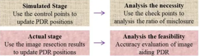
In the study, we use the built-in camera of the smart phone to obtain the indoor environment image. The indoor environment has already been built completely by the mobile mapping system in advance. With the several feature points that their absolute coordinates are known and the image coordinate of the corresponding points, we can process the calculation of image resection and least squares adjustment to rebuild the exterior orientation (EO) of the recording time. There are six exterior orientation elements for each image. They are 3D object space coordinates of camera and three attitude angles respectively. Among them, the 3D objective can be the updated source of external aid. With the combination of the Kalman Filter (KF) and PDR location, we can obtain the optimal value of user location. Research framework of this study is divided into two parts: actual stage and simulation stage. Simulated stage is that the subjects stay in some known control points and use control points to update the PDR position obtaining the best estimation of pace. We will analysis the necessity by the results of simulated stage. Actual stage will use the position of the image resection to replace the known control points. Then, we can analysis the feasibility of image aiding PDR. Figure 1 shows the research process and stages.
Figure 1. Research process and stages
2.2 Pedestrian Dead Reckoning
The study is based on PDR. The principle of PDR is to estimate the heading and travelled distance through the observation of the inertial sensor. As we known the position of the pedestrian can be calculated follow equation (1):
Where Ek, Nk = the coordinate at epoch k
Ek+1, Nk+1 = the coordinate of at epoch k+1
SLk = step length
= the heading at epoch k
With the step detection, step length estimation, heading calculation, we can calculate the position of user at each time. Step detection is needed in order to determine step frequency. Step detection is calculated by Signal Vector Magnitude (SVM). SVM is the total amount of the three-axis acceleration. We can find peaks from the time sequence diagram, and the threshold is set by the empirical method. Figure 2 shows a time sequence diagram of SVM. The green points in the figure are detected peaks and one peak represents one step.
Figure 2. The time sequence diagram of SVM The method of step calibration is to make subjects walk in 30-meter test field and calculate the number of steps. Then we can estimate the average step length. Every subject should calibrate the step before experience and use the result in the formula. In the experiment, the output of gyroscope is integrated overtime to obtain the angle. The heading of next moment is sum of this angle and the heading of previous moment. As a result, we should give an initial heading. The initial heading is
2.3 Image Resection
Use the smart phone camera to take pictures of indoor environment and image coordinate of feature points in single image are observations. The main principle of image resection is collinear equation. The equation (2) shows the collinear equation.
where Xo, Yo = the 2D position of camera
Zo = the height of camera
R11 ~ R33 = rotation matrix
f = focal length
xo, yo = image coordinate of principle point
(X,Y,Z) = object space coordinate of feature points (x,y) = image coordinate of corresponding points In the study, the purpose of the equation is to calculate
unknowns Xo and Yo. AndZo is known and can be given with a
rough height. R11 ~ R33 are known and drive from attitude
angles. The attitude angles (roll, pitch, yaw) are obtained from
the inertial sensor of smart phone. xo, yo, f are obtained from
camera calibration before experiment. There are 6 exterior orientation parameters in traditional image resection method. However, in this experiment, we let the attitude angles and the height of camera to be known. Therefore, there are only two unknowns in this method. It the 2D position of camera. An indoor feature point can offer two image coordinate equations of x and y directions, so we need at least one feature point to process least square adjustment calculation and obtain the camera position. The schematic picture of image resection is as follow.
Figure 3. The schematic picture of image resection
Because the observations and are nonlinear function of unknowns, we should linearize the observation equation before least square adjustment. The linearized equation is as follow equation (3):
(1)
Where Vx, Vy = residuals of observation
, = the approximation value of observation
, = unknown of linearized equation
(Incremental of unknown)
After least squares adjustment, we can get the incremental of unknown and update the approximation value. Conduct iterative computation until the incremental is less than the threshold. Last, integrate the image resection results with PDR and we can evaluate the accuracy of algorithm verifying the effect of vision aiding PDR.
3. EXPERIMENT AND RESULTS 3.1 Experiment Introduction
The attitude of experiment is hand-held attitude. Make the smart phone flat near the subject’s chest, facing upward. Figure 4 shows the attitude of experiment. During the experiment, use the smart phone application to record the output of accelerometer and gyroscope in order to post-process data.
Figure 4. The attitude of experiment
The smart phone of the experiment is i-phone 5S. The camera specification of i-phone 5s is as follow. The pixel size is 0.0015 mm. The image size is 3264*2448. The focal length is 4.1901mm. And the horizontal and vertical field of view (FOV) is 50 degree and 67 degree respectively. Figure 5 shows the three axis of the smart phone coordinate. The roll axis is pointing upward the smart phone. The pitch axis is pointing the right side of smart phone. The yaw axis is pointing to the underneath and vertical to the screen.
Figure 5. The coordinate axis of smart phone
3.2 Pure Inertial Sensor PDR
Firstly, we should discuss the accuracy of pure inertial sensor PDR. The method of accuracy assessment is ratio of misclosure as equation (4). Ratio of misclosure is usually expressed as percentage ratio. Its error meaning is that the system produces how much positioning error every 100 meters.
Where P = ratio of misclosure
, = the difference between the true position and calculated position
= the total length of path
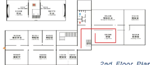
Figure 6 shows the test field of pure inertial sensor PDR. It is on the second floor of the department of Geomatics in National Cheng Kung University. The starting point is marked with the orange triangle. The subject walks down the hall and go into the room 55250. Then walk along the same route back to the starting point. The total length of route is 134.34 meters. End point is the same as the starting point.
Figure 6. The test field of pure inertial sensor PDR Table 1 is the accuracy assessment of pure inertial sensor PDR. In this experiment, 5 subjects conduct the experiment, and the error of step detection is within 5 steps. The biggest error of distance is 7.52 meters. The ratio of misclosure are 8.2%, 8.2%, 4.7%, 2.1%, 4.8% respectively and the mean of 5 subject is 5.6%. Represent that it produces 5.6 meters for each 100 meters. Therefore, we hope to improve accuracy by some control conditions.
Table 1. Accuracy assessment of pure inertial sensor PDR Figure 7 is the positioning result of first subject. The end and start position are the same place. However, due to the drift of inertial sensor, the offset of the start position and the end position is approximately 10 meters. Then we can calculate the ratio of misclosure from the positioning error. The ratio of misclosure is 8.2%.
Figure 7. The result of pure inertial sensor PDR
3.3 Simulated stage
The test field of simulated stage is also department of Geomatics on the second floor of the department of Geomatics in National Cheng Kung University, but the route is a little bit different as shown in figure 8. The total length of route is 59.395 meters. The red points represent the start position and the end point. The purple points are the control points that their positions are known. When walk through the purple positions, the system will update the correct coordinate and heading. Integrating the known position with PDR algorithm may make trajectory more accurate. The test field of actual stage is the same as simulated stage. The blue areas are the approximate range of feature points in the actual stage.
Test Actual steps Detected steps Actual distance (m) Detected distance (m) Distance Error (m) Misclosure (m) Ratio of misclosure (%) 1 205 201 134.34 128.29 6.04 10.988 8.2 2 202 199 134.34 127.02 7.32 11.042 8.2 3 202 201 134.34 134.00 0.34 6.298 4.7 4 190 186 134.34 126.82 7.52 2.814 2.1 5 195 190 134.34 129.55 4.79 6.432 4.8 mean 129.14 5.20 7.515 5.6 (3) (4)
Figure 8. The test field of experiment
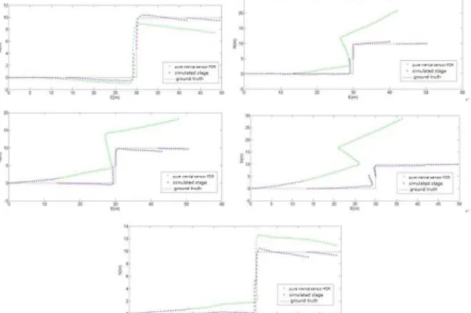
Figure 9 shows the positioning results of simulated stage for five subjects. Green trajectory in the figure is the result of pure inertial sensor PDR. Since the trajectory is based on the previous position, the error of previous position will be apt to propagate to the next position. Moreover, the drift of inertial sensor may affect positioning accuracy. The error is easily and quickly accumulated to the end of the points resulting in gradually declining of positioning. By using the control points to update position and heading, we can make error re-accumulated after we pass through the control points. Blue trajectory is the trajectory after passing three control points and updating positions and headings. The corrected trajectory is closer to the ground truth than that of pure inertial sensor PDR. The actual stage will replace the control points by the image resection results. Then we can verify the feasibility of smart phone camera aiding PDR.
Figure 9. The result of simulated stage
In simulated stage, we calculate the ratio of misclosure of the end point. The accuracy assessment of simulated stage is shown in Table 2. In the experiment, the actual distance is 59.395 meters. The mean of distance error is 2.838 meters. Comparing to the pure inertial sensor PDR, error is reduced a lot. Morever, the ratio of misclosure are 0.3%, 0.6%, 0.3%, 0.1%, 0.2% respectively and the mean of 5 subjects is 0.3%. The results represent that it produces 30 centimeters for each 100 meters. The ratio of misclosure of pure inertial sensor PDR is 5.6%. Accuracy has improved significantly. In addition, updating positions and headings by control points not only enhance the positioning accuracy of check point, but also make the trajectory closer to the ground truth.
Table 2. Accuracy assessment of simulated stage
3.4 Actual stage
The procedure of actual stage is: calibration of interior orientation parameters (IOP), selection of feature points, measuring the image coordinate of feature point, calculating the 2D position of camera. Before taking picture, we should execute camera calibration. IOP include image coordinate of principle point, focal length, lens distortion parameters. The method is to take pictures at the professional calibration field which is set up the artificial coded target in different perspective. Then, use the software to detect and match conjugate points. Simultaneously adjust many images and calculate IOP of every image for correcting lens distortion and execute image resection. When we calibrate the camera, we take the picture at the artificial coded target at the range of 2 meters. As a result, we should do the experiment at the nearly range as doing calibration so as to decrease the error causing by focal length. The following table shows the error of image resection with different range. From the tendency of error, we can conclude that if the range of feature points is far from the range that we doing calibration, the error will be increased. So when we choose the feature points, we should choose them at the range near the range we calibrate the camera. Besides, if the range of feature points is too closed, it is unable to convergence and obtaining a position. Therefore, we should choose an appropriate range to take pictures of feature points.
Position Range (m) Error of image resection with 2 points (m) Error of image resection with 4 points (m) 1 15 2.537 0.509 2 9 1.177 0.558 3 5 1.283 0.373 4 4 0.501 0.388 5 3 0.880 0.039 6 3 1.203 0.529 7 2 divergence 0.138 8 1 divergence 0.050 9 1 divergence 0.017
Table 2. The effect of range
Actual stage and simulated stage are positioning in the local coordinate system. We take pictures at the three control points of the simulated stage. Then choose some identifiable corners as feature points. Although the more the number of feature points are, the more the redundant observations are. Then the accuracy of image resection will also higher. However, in order to improve operational efficiency and consider that system may not detect many feature points in the indoor environment. Therefore we choose four feature points in each image as Figure 10.
Figure 10. Selection of feature points
After taking pictures, we measure the image coordinate system on the computer. Last step is image resection calculation, and then we can get the 2D position of the smart phone. In the experiment, we use 2 and 4 feature points to calculate position
Test Actual steps Detected steps Actual distance (m) Detected distance (m) Distance error (m) Misclosure (m) Ratio of misclosure (%) 1 93 91 59.395 57.860 1.535 0.329 0.6 2 90 93 59.395 54.498 4.897 0.588 1.0 3 98 98 59.395 54.480 4.915 0.306 0.5 4 103 102 59.395 57.426 1.969 0.094 0.2 5 105 104 59.395 58.552 0.843 0.158 0.3 mean 56.563 2.838 0.295 0.5
respectively and compare the positioning accuracy. Table 3 and Table 4 as follow show the results of image resection using 2 and 4 feature points respectively.
With 2 feature points, the positioning error are 0.501 meters, 0.880 meters, 1.203 meters, and the mean is 0.861 meters. The accuracy is good enough apply in indoor positioning and represents that we need only few points to position in some monotonous and the environment that is lack of feature points. The result of image resection is still able to perform and reach enough accuracy. Position Range (m) Actual position (m) Calculated position (m) Positioning error (m) C1 4 (24.178,0) (24.360,-0.454) 0.501 C2 3 (31.293,9.871) (32.109,10.200) 0.880 C3 3 (47.764,9.871) (46.654.9.408) 1.203 mean 0.861
Table 3. Image resection with 2 feature points
The follow table shows the result of image resection using 4 feature points. The positioning errors are 0.388 meters, 0.039 meters, 0.529 meters, and the mean is 0.319 meters. When feature points are added from 2 points to 4 points, the positioning error decrease from 0.861 meters to 0.319 meters. In addition, automatic detection of more than four feature points isn’t a difficult work. The result illustrates that image resection can be used in indoor position, and reach the accuracy of decimetre. Position Range (m) Actual position (m) Calculated position (m) Positioning error (m) C1 4 (24.178,0) (24.371,-0.317) 0.388 C2 3 (31.293,9.871) (31.330,9.883) 0.039 C3 3 (47.764,9.871) (47.287,9.641) 0.529 mean 0.319
Table 4. Image resection with 4 feature points Finally, we integrate the result of image resection with PDR, and the trajectory is shown as Figure 11. Although it is impossible to update the non-biased position, the trajectory is closer to the ground truth than pure inertial sensor PDR. The result illustrates that vision aiding PDR for indoor navigation is effective.
Figure 11. The result of actual stage
Table 5 is the accuracy evaluation of actual stage. In actual stage, we use the position of image resection to update the PDR position. We also calculate ratio of misclosure on the check point. The results of 5 subjects are 0.8%, 1.6%, 1.0%, 0.8%, 0.9% respectively, and the mean is 1.0%. The results represent that it produces 1 meter for each 100 meters. Compared to the pure inertial sensor PDR, the ratio of misclosure is decreased
from 5.6% to 1.0% and the result of actual stage is consistent to the simulated stage. We can conclude that vision aiding PDR with smartphone for indoor navigation is available.
Table 5. Accuracy assessment of actual stage
Compare the result of actual stage to the pure inertial sensor PDR and the ratio of misclosure is decreased from 5.6% to 1.0%, so the vision aiding PDR can make the accuracy rise about 82%. Verify that the image can aid the inertial sensor for indoor positioning and navigation effectively.
4. CONCLUSION
The results of vision aiding PDR show that if we don’t use the camera positions to constrain the PDR trajectory, the positioning accuracy may be decreased due to the drift of inertial sensor. Besides, the principle of the PDR is to calculate the next position from the previous position. The error of subsequent positions will be accumulated successively due to the error propagation of forward positions. The experiment results illustrate that the ratio of misclosure of pure inertial sensor PDR is 5.6% while the PDR trajectory with vision aiding is 1.02%. Using the 2D position form image resection to update positions can make the trajectory closer to the ground truth and promote the position and navigation accuracy dramatically. Currently, vision aiding PDR is implemented with post-processing attributed to the effectiveness of the smart phone hardware may not load the image matching algorithm. As a result, we store the data of sensor and image and process the data on the computer, verifying images can assist PDR in indoor position and navigation. Although, now we can’t achieve real- time processing on the smart phone, we hope that we will adopt cloud computing in the future. The system uploads data to the server workstation and returns the object point information to smart phone. Progress image resection algorithm and construct pedestrian navigation system to achieve the effectiveness of real-time indoor positioning.
5. REFERENCES
Bashir Kazemipur, Zainab Syed, Jacques Georgy, Naser El-Sheimy (2014). Vision-based Context and Height Estimation for 3D Indoor Location
Li-Hung Chen , Kuei-Ping Chang , Kai-Wei Chiang (2014). The Performance Analysis of Visual Odometry Assisted Inertial Navigation System.
Q. Ladetto, B. Merminod (2002). Digital Magnetic Compass and Gyroscope Integration for Pedestrian Navigation
Ronald Azuma , Mark Ward (1991). Space resection by collinearity Mathematics behind the optical ceiling head-tracker. Ruizhi Chen, Ling Pei, Yuwei Chen (2011). A Smart Phone Based PDR Solution for Indoor Navigation. ION GNSS 2011Proceedings. Test Actual steps Detected steps Actual distance (m) Detected distance (m) Distance error (m) Misclosure (m) Ratio of misclosure (%) 1 93 91 59.395 57.860 1.535 0.474 0.8 2 90 93 59.395 54.498 4.897 0.977 1.6 3 98 98 59.395 54.480 4.915 0.623 1.0 4 103 102 59.395 57.426 1.969 0.480 0.8 5 105 104 59.395 58.552 0.843 0.864 0.9 mean 56.563 2.838 0.684 1.0
Sheng-Cheng, Yeh Chen-Chih Chiu, Cheng-En Hung (2010). A Study of Indoor Locating and Tracking Systems Based on Wireless Local Networks with RFID Technique
Sou-Yung, Hsieh (1998). The Study of the Three Dimensional Navigation System Hardware Structure by Integrating GPS with INS.