177
Compression of Chinese Character Patterns in
Document Images Based on Rectangular Region Partitioning Using Contour Information and Huffman Coding
*C
HIH-H
SUANT
ZENGANDW
EN-H
SIANGT
SAI†Department of Computer and Information Science, National Chiao Tung University,
Hsinchu, Taiwan 300, ROC e-mail: {chtzeng,whtsai}@cis.nctu.edu.tw
Abstract: Document image compression is important in modern communication systems, and many lossless/lossy compression algorithms have been proposed for a variety of documents. In documents with Chinese characters, there are 5401 commonly used Chinese character patterns. It requires a large amount of space to store all Chinese character patterns of different fonts in computer systems. However, the compression of Chinese character patterns has not been extensively studied. In this paper, a new document image compression method is proposed. The purpose is to provide an effective encoding algorithm for Chinese character patterns and in the meantime obtain good compression results for general documents. The proposed method includes rectangular region partitioning, encoding of rectangular regions, and encoding of contour information. An input image is first partitioned into nonoverlapping blocks, and each block that contains black pixels is partitioned into nonoverlapping rectangles. The rectangles are then encoded in an effective fashion.
For the purpose of lossless compression, contour information is exploited to encode the contour blocks with static Huffman coding. Experimental results showed that the proposed method is not only suitable for Chinese documents but also has good performance for general documents.
Keywords: document image compression, chinese character pattern, rectangular region partitioning, contour information encoding, Huffman coding
1. Introduction
With advances in communication technologies, lots of documents in traditional office environments are scanned into computers as images for fast
*This work was supported partially by the National Science Council, ROC under grant NSC86-2213- E009-113.
†To whom all correspondences should be sent.
archiving and transmission. Document images with printed and handwritten information in black and white pixels constitute a subclass of digital images.
The sizes of scanned documents are usually large and so require large storage space and time to store and transmit. Document image compression (DIC) is the key technique to solve these problems.
Many lossless/lossy DIC algorithms have been proposed for a variety of documents [1, 8, 9]. Run-length coding and CCITT Group 3 and 4 compression algorithms are conventional methods for lossless compression of document images [2]. The JBIG standard combining a local context model with arithmetic coding has the best performance in lossless compression [2, 3]. However, the JBIG algorithm is slow in arithmetic coding, compared to conventional CCITT Group 3 and 4 compression algorithms. A template matching method for DIC was proposed by Witten et al. [4], in which connected groups of pixels, corresponding approximately to individual characters, are first extracted from the image. These connected components are then matched against an adaptively constructed library of patterns seen so far, and the resulting sequence of symbol identification numbers is coded. When the document image contains mostly alphanumeric symbols, the compression result is much better than those methods mentioned previously. However, for those images that contain complex strokes such as Chinese characters, it is hard to apply simply the template matching method to achieve effective compression. Mohamed and Fahmy [5] proposed a method that partitions the input image into a near minimum number of nonoverlapping rectangles and encodes the coordinates of the opposite vertices of each rectangle. Although this method is fast and the compression result is better than most conventional methods, the partitioning algorithm produces a lot of small rectangles around skewed strokes of characters or skewed line drawings.
In this situation, encoding of the opposite coordinates of each rectangle will be less efficient. In the above studies, it is clear that the compression of Chinese characters is difficult and demands further research.
Targetting the difficulty of compressing Chinese character patterns, Tsay et al. [6] proposed a redundancy-gathering algorithm based on arithmetic coding.
Though the result of simulation in this study is good, the computational complexity is high since a huge tree of nodes are used. Lai and Liaw [7] presented a lossless compression method by 2-D run-lengths with line-segment prediction. Though the method is fast and has good compression results, there is still much to improve.
In this study, we propose a novel lossless DIC method, especially suitable for Chinese character patterns. Since each Chinese character pattern is composed of many straight strokes, it is efficient to partition the strokes of each character
into nonoverlapping rectangular regions as Mohamed and Fahmy [5] proposed.
Furthermore, it is obvious that there exists a high correlation between the boundaries of strokes. A local context model based on pixels is commonly established to take advantage of the correlation [9]. The proposed method also establishes a local context model, but based on blocks instead. The simulation results show that the proposed method is not only efficient for compressing specific document images containing lots of Chinese character patterns but also suitable for general document images.
The remainder of this paper is organized as follows. In Section 2 we describe the principle of the proposed DIC method. In Section 3 we describe the proposed rectangular region partitioning technique. Algorithms for encoding of the rectangular regions and encoding of contour information are proposed in Sections 4 and 5, respectively. We will also examine the effectiveness of each proposed algorithm right after the algorithm is described in each section. The paper concludes with Section 6.
2. Principle of Proposed Method
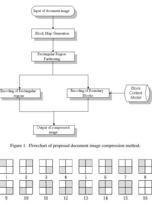
As shown in Fig. 1, the proposed method includes block map generation, rectangular region partitioning, encoding of rectangular regions, and encoding of contour blocks.
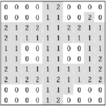
The proposed method is based on processing blocks, so an input image S is first decomposed into nonoverlapping 2×2 blocks. In each block, there are 16 different combinations of black and white pixels, as shown in Fig. 2. A block map B is also generated when the image S is decomposed. The map B is a ternary matrix with the size of a quarter of that of the input image S, i.e., if the size of S is 2n×2n, then that of B is 2n−1×2n−1. The elements bij of B are defined as
=
otherwise, ,
2
, black are block ing correspond the
in pixels the all if , 1
, white are block ing correspond the
in pixels the all if , 0 bij
where i, j = 1, 2,…, 2n−1. In Equation (1), bij= 0 represents a white block, bij= 1 represents a black block, and bij= 2 represents a mixed block including black and white pixels. Based on the information of the block map B, an approximate image of the original image can be obtained. The difference between the original input image and the approximate image comes mostly from the contours of (1)
Figure 1. Flowchart of proposed document image compression method.
Figure 2. 16 different kinds of pixel value combinations in each 2×2 block.
uniform regions in the original image. If the block map is compressed and transmitted, then the receiver can decompress the block map and reconstruct a lossy version of the original image by the block map. If the contour information is also compressed and transmitted, then the receiver can restore the original image by using the combined data of the contour information as well as the
block map. Hence, the subsequent stages of the proposed method aim at good compression of the block map and the contour information.
As mentioned earlier, Chinese character patterns contain a lot of straight strokes. To exploit the general features of Chinese character patterns for compression, new rectangular region partitioning and encoding method are proposed to partition the block map into nonoverlapping rectangles and then encode them. It is worthy to notice that the use of the block map makes the characteristic of the straightness of strokes more apparent than that in the original image; and so fewer rectangles will be produced from the block map than from the original image. This makes the encoding of the block map more efficient.
Finally, to encode the contour information, a local context model is established to model the relation between each contour block and its 8 neighbor blocks. The context model is developed according to our observation that the probability of the appearance of a specific block in the center of a 3×3 block group varies with different combinations of the neighboring 3×3 blocks. As a result, the efficiency of the proposed contour block coding can be improved further by the use of static Huffman coding.
The details of the proposed processes of rectangular region partitioning, encoding of rectangular regions, and encoding of contour information are described in the following sections.
3. Block Map Partitioning
The block map of an input image makes the straightness of strokes more apparent, so it is advantageous to partition the regions of strokes into a number of rectangles. Several techniques have been proposed to partition a region into rectangles [10, 11]. Though Mohamed and Fahmy’s method [5] is greedy and not optimal, it is fast and near optimal. In addition, the block map in our technique is a ternary matrix; only the binary matrix, however, is considered in Mohamed and Fahmy’s method [5]. Therefore, a new partitioning algorithm, called block map rectangular partitioning (abbreviated as BMRP), is proposed in this study to take advantage of using the block map.
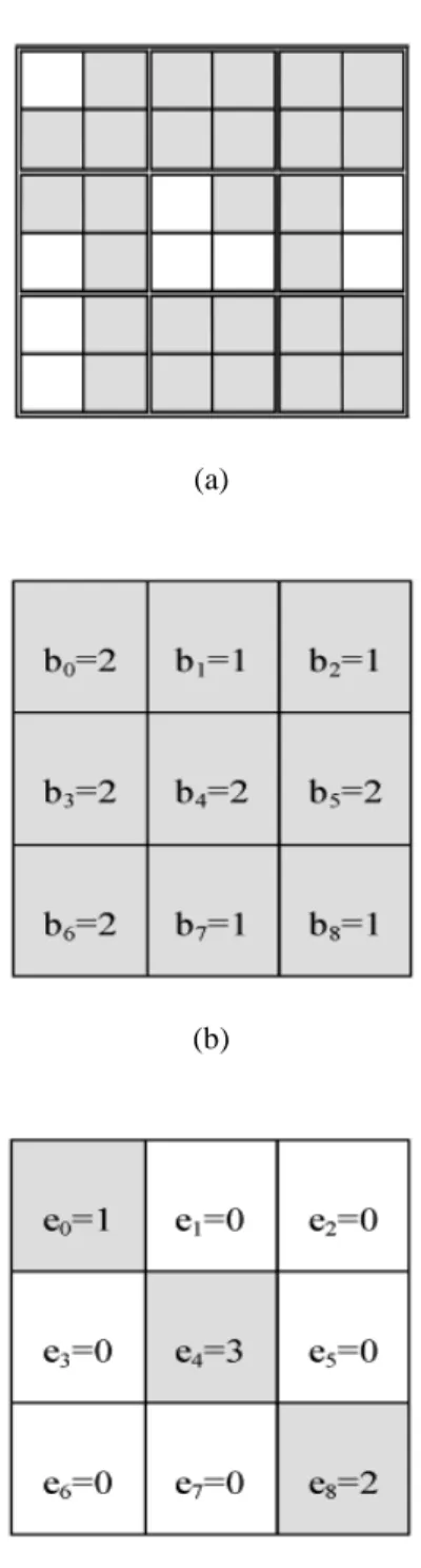
As an example, see Fig. 3(a) which is the block map of a Chinese character image. By applying the proposed BMRP algorithm to the block map in Fig. 3(a), the shadowed region (stroke region) in the block map can be partitioned into nonoverlapping rectangles as shown in Fig. 3(b). For compression purpose, an encoding matrix E is generated in the BMRP process, as shown in Fig. 3(c). The size of the matrix E is the same as that of the matrix B, and the element eij of E is defined as
(a)
(b)
(c)
Figure 3. (a) Block map matrix B of a Chinese character image. (b) Partitioning result of matrix B into nonoverlapping rectangles. (c) Encoding matrix E of block map matrix B.
(a)
(b)
(c)
Figure 4. (a) A small hole in an input image. (b) The corresponding block map of the input image (a). (c) The corresponding E matrix.
=
−
otherwise.
, 0
; block inner mixed a or block isolated an
is ) , ( if , 3
rectangle;
a of vertex right bottom the
is ) , ( if , 2
; rectangle a
of vertex left top the is ) , ( if , 1
j i
j i
j i
eij
Note that eij= 3 means that the block bij is isolated, or is a block with mixed colors (i.e., bij= 2) and the 8 neighboring blocks of bij are of mixed color or black. Isolated blocks exist in contours that contain isolated pixels in the input image. On the other hand, by using the block map, the proposed method partitions the input image in a low resolution. When a small hole exists in the center of a bold stroke of a character, it will result in a mixed block having eight black or mixed neighboring blocks. This situation happens in small characters or small defects in strokes, as shown in Fig. 4. For the purpose of lossless compression, such mixed-inner blocks also have to be tracked and coded. By encoding the matrix E, the block map can be compressed in an efficient way.
The BMRP algorithm proceeds in a raster scan fashion. When a new rectangle is found, the corresponding locations of the two opposite vertices in matrix E are assigned nonzero values. The original rectangle can be reproduced from the two nonzero elements of the matrix E. As a result, all rectangles found in the block map can be reproduced by the information provided in matrix E. The detail of the BMRP algorithm is described as follows.
Algorithm 1 Block Map Rectangular Partitioning (BMRP)
Step 1: Scan the blocks in the input m×n block map matrix B one by one and encode the result with a matrix E.
Step 2: If an unprocessed black or mixed element bij in B is found (bij = 1 or 2), then a new rectangle is encountered. Set eij = 1 as the top left vertex of the new rectangle and set k = j. Perform the following steps.
(1) If bi(k+1) is not white (bi(k+1) = 0) or is processed, then set k = k + 1 and repeat Step 2(1).
(2) Regard eik as the top right vertex of the new rectangle and set l = i.
(3) In a row-by-row manner, scan downward the matrix B in the column range between the column location, j, of the top left vertex and the column location, k, of the top right vertex. Check if the segment in (2)
the next row bounded by locations (l + 1, j) and (l + 1, k) meets either of the following two conditions.
(Condition 1) More than one white block exists in this row.
(Condition 2) Blocks b(l+1)( j−1) and b(l+1)(k+1) are both unprocessed black or unprocessed mixed blocks (b(l+1)( j−1), b(l+1)(k+1)= 1 or 2).
If neither of the condition is met, then set l = l + 1 (i.e., to scan the next row) and repeat Step 2(3);
(4) If coordinates (l, k) = (i, j ), then set elk= 3 (isolated block); else, set elk= 2 as the bottom right vertex of the rectangle.
(5) For each block, bpq, in the new rectangle, set each block in the new rectangle as being processed, and if bpq= 2 (mixed block) and all of its eight neighbor blocks are not white, then set epq= 3 (inner mixed block).
Step 3: Output the matrix E.
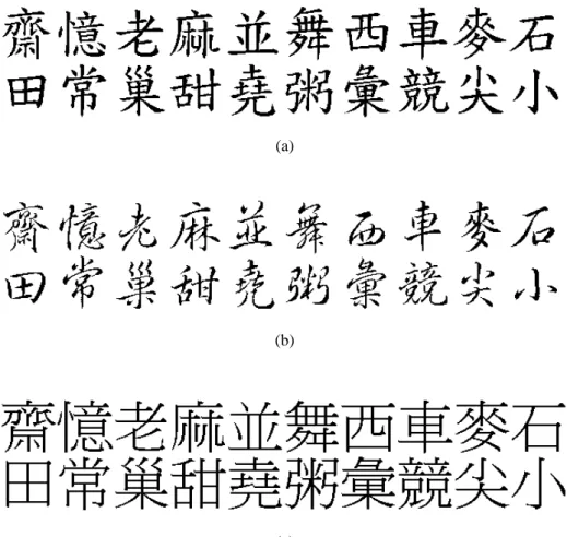
We shall first examine the performance of the BMRP algorithm. Two categories of images are used as inputs. For Chinese characters, there are at least 5401 commonly used characters. The sung-style, formal-style, and running-style fonts are commonly used in printing. Because the proposed method is to achieve good compression result for commonly used character patterns, in addition, general documents contain both simple and complex characters, 200 characters including simple and complex characters of each font are randomly chosen in our experiment. Each character has a resolution of 64×64. Figure 5 shows an example of the experimental images of Chinese character patterns. To test the effectiveness of the BMRP for general document images, six document images of different types and sizes are used. Each general document image is scanned in 300 dpi.
These images are shown in Fig. 6.
Table 1 summarizes the experimental result of using the BMRP algorithm.
The average numbers of produced rectangles per character pattern of each font were 43.8, 48.5, and 36.8, respectively. The running-style fonts resulted in more rectangles than the other two fonts. A possible reason is that the running-style fonts contain more skewed strokes than the other two fonts and skewed strokes are partitioned into more rectangles than vertical or horizontal strokes.
Furthermore, comparing with Mohamed and Fahmy’s method [5], we found that the number of rectangles generated by the BMRP algorithm was about half of that generated by Mohamed and Fahmy’s method [5]. The reduction in the number of rectangles will yield better results in rectangle and contour information encoding, proposed in the following sections.
(a)
(b)
(c)
Figure 5. Test Chinese character patterns. (a) Formal-style font. (b) Running-style font.
(c) Sung-style font.
(a)
(b)
Figure 6. Test images of different types and sizes. (a) 320×200 (b) 1100×1548 (c) 640×480 (d) 1024×768 (e) 1024×768
(d) (c)
(e)
Table 1. Experimental results of proposed BMRP and Mohamed and Fahmy’s method (MFM) for partitioning Chinese character patterns into rectangles.
Chinese font MFM
(No. of rectangles/pattern)
BMRP
(No. of rectangles/pattern)
Percentage of Improvement
Formal-style 84.8 43.8 48.70%
Running-style 96.7 48.5 49.84%
Sung-style 73.5 36.8 49.93%
4. Encoding of Rectangular Regions
After the block map is partitioned into rectangles and the matrix E is produced, the next stage is to encode the coordinate information. The encoding algorithm should be efficient to maintain the advantage of the BMRP algorithm.
The proposed algorithm for this purpose processes input matrices from left to right and from top to bottom as the BMRP algorithm. There are three possible nonzero values in the matrix E, and each nonzero value is assigned a different
codeword. These codewords are not equal in length, because the probability of appearance of each nonzero value is not the same. Basically, the occurrence probability of the matrix element ‘1’ (top right block) and ‘2’ (bottom block vertex) are much higher than ‘3’ (isolated or inner mixed block), so it is efficient to use the static Huffman code to encode these symbols. Table 2 gives the code table used in the experiment.
Additionally, skewed strokes result in small rectangles and the opposite vertices of these rectangles are usually connected. That is, if two rectangles are connected, the bottom right vertex of the upper rectangle may be a neighbor of the top left vertex of the lower rectangle. This shows that if a chain code type method is employed, the codes for compressing these vertices can be more compact. In the proposed algorithm, if eij is a nonzero element in matrix E, a tree Tij whose root is eij is constructed. Each node, p, of the tree has the following properties.
Property 1: p is a nonzero and unprocessed element in the matrix E.
Property 2: If q is a nonzero element in the matrix E and is a southwestern (sw), southern (s), southeastern (se), or eastern (e) neighbor of p, then q is also a node of the tree Tij. We said that p is the parent node of q, and q is the child node of p.
Property 1 says that each node of the tree Tij must be a nonzero element in the matrix E. And Property 2 says that the tree Tij is expanded from eij in four directions (sw, s, se, and e) by including each nonzero neighboring element into the tree. The expansion of the tree Tij stops when no nonzero neighbor is found.
A depth first search (dfs) algorithm is used to expand the tree. If a nonzero child epq is encountered during the dfs, codewords used to encode the nonzero element’s direction and value are assigned. Table 3 shows the codewords used to encode the directions in our experiment and Table 2, as mentioned previously, shows the codewords used to encode the nonzero value. Then, the tree is expanded by including nonzero children whose parent is epq and the dfs algorithm recursively
Table 2. The codewords for the vertex symbols.
Vertex Type Symbol Codeword
top left 1 1
bottom right 2 01
isolated or mixed-inner 3 00
traverses the children expanded using dfs. At last, the dfs algorithm stops when all the children in the tree are visited and no more nonzero child is found.
We illustrate the basic concepts of the proposed algorithm using Fig. 7, which shows the tree structure of the relationship defined in the proposed algorithm. Figure 7(a) shows all possible branchings from a nonzero element during execution of the proposed algorithm. Figure 7(b) shows the final tree structure. The black boxes represent nonzero elements and the white boxes represent zero elements in the matrix E. In Fig. 7(a), eij is the nonzero root of the tree. The tree is expanded in four directions by including the root’s nonzero
Table 3. The codewords for encoding directions.
Direction Codeword
southwestern (sw) 00
southern (s) 01
southeastern (se) 10
eastern (e) 11
Figure 7. An example tree structure in rectangular region encoding.
neighbors. For example, nodes, A, B, C, and D are the southwestern (sw), southern (s), southeastern (se), and eastern (e) neighbors of the element eij, respectively.
Only A is a nonzero element (black box). As a result, a solid line between eij and A is used to represent a real branch in the tree, and the other three dashed lines between the pairs of eij and B, eij and C, and eij and D are used to represent fake branches in the tree. The proposed algorithm first encodes node A and then search A’s child nodes to see if any nonzero child exists. If there exists a nonzero child node of A, the nonzero child node is expanded in the tree. Otherwise, the proposed algorithm traces upward to A’s father node and searches if any nonzero child exists. At last, the algorithm stops when no nonzero child exists. In this example, after node A is visited and encoded, node F and node K are visited and encoded, respectively. In this process, it is found that there is no nonzero child of node K, so the trace goes upward to node F and then node G is processed and encoded. At last, no nonzero child of node G was found and the algorithm stops.
The final tree structure is generated to be Fig. 7(b). Note that there is a dashed line between node G and node K because node K is already visited and encoded in the tree as a child node of F.
An algorithm is presented below to summarize the proposed rectangular region encoding process as described above.
Algorithm 2 Rectangular region encoding
Step 1: Read in the matrix E with size m×n which is to be encoded. Use 32 bits to encode m first. For each row i in E, perform the following steps.
Step 2: If all the elements eij in row i are zero (where j = 1, 2,…, n), then represent the row by a binary value “0”; else, go to step 3.
Step 3: (Encode nonzero elements) If a nonzero element is encountered in row i, then add a prefix “1” to the code, indicating the existence of a nonzero element, and then attach the codeword that identifies the nonzero element, 1, 2, or 3 to the prefix. The column location of eij is specified by b bits which are defined by the following Equation (3):
. previously d
encountere element
nonzero the
is
and
element nonzero
first not the is if
element;
nonzero first
the is if )], ( [log
], [log
2 2
ik ij ij
e e e k
n n b
= −
If eij is the first nonzero element, then the column location of eij is specified by “j” with b bits; else, the column location of eij is specified by “j − k” with b bits.
(3)
Step 4: (Encode nonzero neighbors) Traverse the tree whoose root is eij by dfs until no more nonzero element in the tree is found. During the traversal process, for each nonzero element epq in the tree, perform the following encoding steps.
(a) Add a prefix “1”, indicating that a nonzero child exists.
(b) Append to the prefix the codewords that identify the direction (sw,s,se,e) and the value (1, 2, 3) of the element epq.
(c) If epq has no child node, then add a postfix “0”, indicating that no child node follows epq.
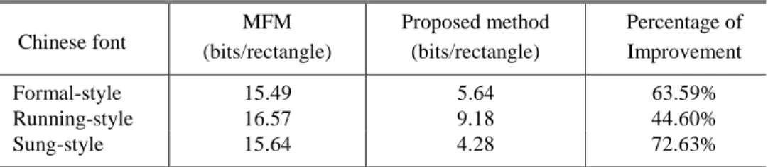
The effectiveness of the proposed encoding algorithm is shown in Table 4.
For formal-style and sung-style Chinese character patterns, the numbers of bits required to encode a rectangle are 5.64 and 4.28, respectively. For the running- style fonts, the number of bits required to encode a rectangle is 9.18 The fact that more bits required by the running style than the other two styles results from the fact that the running style has smaller rectangles after partitioning. For the formal-style and the sung-style, the proposed encoding method has at least 60% improvements over Mohamed and Fahmy’s method [5]. For the running style, the improvement is limited by the existence of skewed strokes which result in isolated blocks and small rectangle regions. But the performance is still better than Mohamed and Fahmy’s method [5] by 40%.
Table 4. Experimental results of encoding of rectangular regions (MFM: Mohamed and Fahmy’s method).
Chinese font
MFM (bits/rectangle)
Proposed method (bits/rectangle)
Percentage of Improvement
Formal-style 15.49 5.64 63.59%
Running-style 16.57 9.18 44.60%
Sung-style 15.64 4.28 72.63%
Furthermore, we examine the relationship between the number of rectangles and the compression rate. In the proposed algorithm, each rectangle is represented by the top left and the bottom right vertices of the rectangle. It implies that the more rectangles are generated, the more vertices are to be encoded. In general, smaller numbers of rectangles will yield better compression rates.
More specifically, let R be the compression rate, N be the number of rectangles, W and H be the width and height of the input image I, respectively.
The total number of bits required to encode the rectangular regions can be computed as the sum of the bits required to encode the top left and bottom right vertices of each rectangle, so that we can express the relationship between the number of rectangles and the compression rate as
%, 100 )
(
% 100 )
(
2 1 2
1 ×
× + +
≈
× × + +
=
∑ ∑
=
=
H W
z l d H
W
z l d R
N i
i i N
i
i i
(4)
where di(2≤di≤3) is the number of bits required to represent the type of vertex i, and li(0≤li≤log2W ) is the number of bits required to encode the location of the vertex i, and ( 21( i))
N
i di l
z n
∑
= + is the number of bits required to encode the non-vertex rows in the image. From Equation (4), though we cannot claim that N is inversely proportional to R, it can be seen that if N is decreased enough, R will be decreased. That is, when the number of rectangles is small, a better compression rate will be produced. In the experiments, our proposed method can improve the method proposed by Mohamed and Fahmy over 50% on average in reducing the number of rectangles. This shows that the proposed method has much improvement on the compression rate.The statement above can be verified by the experimental result shown in Table 5. It can be found that running-style patterns are with more rectangles than Sung-style patterns. As a result, running-style patterns yield worse compression results than Sung-style patterns.
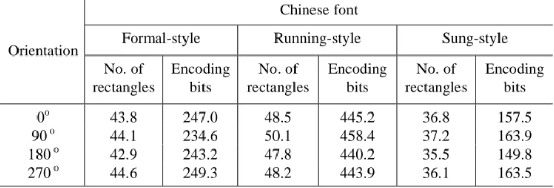
In addition, we investigate the effect of the structure and density of the involved images on compression rates. Firstly, we consider the number of rectangles produced and the encoding results of the same character patterns in
Table 5. Experimental results of the number of rectangles generated and the encoding bits of the same character pattern in different orientations.
Chinese font
Formal-style Running-style Sung-style Orientation
No. of rectangles
Encoding bits
No. of rectangles
Encoding bits
No. of rectangles
Encoding bits
0o 43.8 247.0 48.5 445.2 36.8 157.5
90 o 44.1 234.6 50.1 458.4 37.2 163.9
180 o 42.9 243.2 47.8 440.2 35.5 149.8
270 o 44.6 249.3 48.2 443.9 36.1 163.5
different orientations (0o, 90o, 180o, and 270o). Table 5 shows the numbers of rectangles generated and the encoding bits of different Chinese character patterns in different orientations. It can be noted that character patterns in different orientations will result in different numbers of rectangles generated and different encoding bits though the densities of characters are the same. However, the variance of the numbers of resulting rectangles is small. It shows that the results of the proposed method of rectangular region partitioning do not greatly depend on the structure of the image involved. Besides, in the experiment, more rectangles do not result in more encoding bits. This also shows the effectiveness of the proposed rectangular region encoding method.
5. Encoding of Contour Information
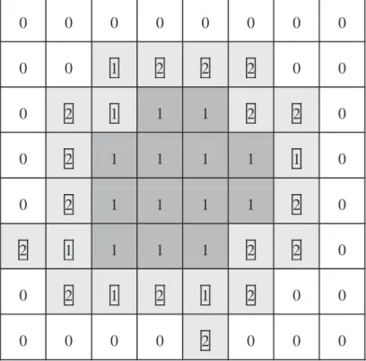
At last, those blocks, which contain stroke contours, in the block map are encoded to achieve a lossless compression result. For example, Fig. 8 shows a block map of a blob stroke. For each nonzero block who has at least a neighboring block whose value is “0”, the nonzero block is identified as a contour block which needs to be encoded. Otherwise, the nonzero block is an inner block. For the reason that values of inner blocks must be “1”, which means all pixels in inner blocks are black, inner blocks need not be encoded. As illustrated in Fig. 8, the value of each contour block is marked by a square bounding box and each contour block has a light shadowed region. Each inner block is marked with a dark shadowed region. Owing to the patterns of contour blocks which are mixed with black and white pixels, to encode these contour blocks, our experiments showed that the appearance of the central (contour) block is closely related with the combination pattern of its 8 neighbors. For example, in a general document image, Fig. 9 shows a combination of the 8 neighboring blocks, the probability of each distinct block Bi which appears in the neighborhood center are shown in Table 6. Under the neighborhood combination illustrated in Fig. 9, it is obvious that the sum of the probability is over 90% when X = B7 and X = B15. On the other hand, when X = B1, X = B5, X = B9, X = B10 and X = B14, the probability are zero. As a result, for the purpose of more effective encoding of contour blocks, a context model is used to exploit such appearance relations.
In the proposed method, we establish a of Huffman codebook to exploit the relation stated above. Firstly, as shown in Fig. 8, we assume that the 8 neighboring blocks of a contour block X are represented by “0” or “1”. The combination Y of the 8 neighboring blocks can be defined as follows:
Y = {N0, N1, N2, N3, N4, N5, N6, N7} (5)
Figure 8. The center block X and its 8 neighbors.
N1 N2 N3
N4 X N5
N6 N7 N8
Figure 9. Contour blocks (light shadowed region) and inner blocks (dark shadowed region) of a block map.
0 0 0 0 0 0 0 0 0 0 1 2 2 2 0 0 0 2 1 1 1 2 2 0 0 2 1 1 1 1 1 0 0 2 1 1 1 1 2 0 2 1 1 1 1 2 2 0 0 2 1 2 1 2 0 0 0 0 0 0 2 0 0 0
where Ni∈{0, 1} and i = 0, 1 , 2,…, 7. In Equation (5), Ni represents the ith neighbor of the central block. When Ni= 0, it means that the corresponding block is white; otherwise, it is black or mixed. It is noted that there are 28= 256 different combinations of the 8 neighboring blocks. Let Yj represent the jth of the 256 neighborhood combinations, and Bi represents the central block whose index is i (i = 1, 2,…, 15). We can compute the probability p(Bi|Yj) of each distinct central block under each distinct neighborhood combination Yj using the following equation:
) , (
) ) (
(
j j i j
i N Y
Y B Y N
B
p = (6)
where N(BiYj) is the number of situations that block Bi is in the center with neighborhood combination Yj in an image, and N(Yj) is the number of situations that neighborhood combination Yj occurs in an image. In our experiment, the probability p(Bi|Yj) does not vary greatly with different input images. Furthermore, based on the probability value of p(Bi|Yj), a static Huffman codebook with 3840(= 256×15) entries can be established and can be used to encode the central block. Let lji be the codeword length of the central block Bi under the combination Table 6. Huffman codewords for Yj= {0, 0, 0, 1, 1, 1, 1, 1} where the symbol “×” means that the Huffman codeword is not exist.
Yj i(Bi) p(X|Yj) Huffman codeword
Huffman codeword length (lji)
31 1 0.0 × 0
31 2 0.000154 111111110 9
31 3 0.0102 11110 5
31 4 0.008017 111110 6
31 5 0.0 × 0
31 6 0.000308 11111110 8
31 7 0.4764 0 1
31 8 0.000771 1111110 7
31 9 0.0 × 0
31 10 0.0 × 0
31 11 0.000154 111111111 9
31 12 0.0213 110 3
31 13 0.0176 1110 4
31 14 0.0 × 0
31 15 0.4653 10 2
Yj of neighbors. The average codeword length Lj for the corresponding combination Yj can be computed as follows:
. 255 , , 2 , 1 , 0 where , ) (
15 0
= K
×
=
∑
= p BY l j
L
i
ji j i j
In the previous example, when the combination of the neighboring blocks is Y31= {0, 0, 0, 1, 1, 1, 1, 1} as shown in Fig. 10, the probability of each distinct block which appears in the center are shown in Table 6. The average codeword length L31 is 1.65 bits which is much smaller than the codeword length 4 bits which is the codeword length required to encode each block directly by its index.
The established Huffman codebook of the contour information is put in a file, which we call the context model M. An algorithm is given below to illustrate the proposed contour information encoding method discussed above.
(7)
Figure 10. The combination, Y = {0, 0, 0, 1, 1, 1, 1, 1}, of the eight neighbors of the center block, X.
Algorithm 3 Encoding of contour information
Step 1: Read in the context model M and the m×n block map matrix B which is used previously in rectangle partitioning.
Step 2: For each element bij in the matrix B, if bij= 2, or bij= 1 and there exists at least one neighboring block of bij whose value is “0”, find out the neighborhood combination Yj of the central contour block, and perform the following steps.
(a) If the contour block is Bi, find the corresponding codeword wij by locating the entry (Bi, Yj) in the context model M.
(b) Encode the contour block by the codeword wij. Step 3: Stop.
N1 N2 N3
N4 X N5
N6 N7 N8
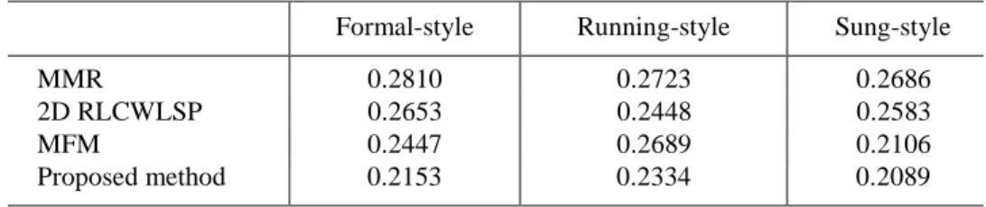
The bit rates for compressing Chinese character patterns are shown in Table 7, from which we see that the rates for the three Chinese font types are 0.253, 0.2334 and 0.2086, respectively. Besides, the average Huffman codeword length of contour blocks is shown in Table 8. The average codeword length of each font is about 1.6, that is 60% smaller than that resulting from encoding each block directly with its index (4 bits). Also, the performance of the proposed method was at least 15% better than those methods used to compress Chinese character patterns. It is worth to note that with Mohamed and Fahmy’s method [5] it requires the highest bit rate to compress the running style. A reason is that the running-style patterns contain more skewed strokes that degrade the effectiveness of rectangle partitioning. However, in the proposed method, BMRP reduces the effect of the skewed strokes so that the bit rate of compressing the running style is still close to those required for the other two styles.
The effectiveness of the proposed method in compressing general document images is also examined, and the experimental results are shown in Table 9 and Table 10. The performance of the proposed method is better than other methods except the standard JBIG. However, the compression time required by the proposed method is half of the time required by JBIG. Especially, when compressing the Chinese document image of Fig. 6(d), our result was close to the performance of the JBIG.
Table 7. The bit rates of compression of Chinese character patterns. (MMR: Modified Modified READ (Relative Element Address Designate) coding; 2D RLCWLSP: 2D Run- Length Coding With Line-Segment Prediction; MFM: Mohamed and Fahmy’s method).
Formal-style Running-style Sung-style
MMR 0.2810 0.2723 0.2686
2D RLCWLSP 0.2653 0.2448 0.2583
MFM 0.2447 0.2689 0.2106
Proposed method 0.2153 0.2334 0.2089
Table 8. The average Huffman codeword lenghth of compression of Chinese character patterns.
Formal-style Running-style Sung-style Average Codeword
Length (bits) 1.62 1.68 1.54
Table 9. Total number of encoding bits of general document images. (MMR: Modified Modified READ (Relative Element Address Designate) coding; MFM: Mohamed and Fahmy’s method)
Test images MMR MFM JBIG Proposed
method
a 31492 28473 18203 22598
b 84716 82673 67172 79131
c 32351 30476 20687 27461
d 264859 236907 148400 181112
e 386906 357179 138213 226424
Table 10. Processing time of different encoding methods in seconds. (MMR: Modified Modified READ (Relative Element Address Designate) coding; MFM: Mohamed and Fahmy’s method)
Test images MMR MFM JBIG Proposed method
a 0.31 0.45 1.97 0.79
b 1.21 1.46 5.28 1.93
c 0.62 0.78 1.75 1.05
d 2.76 2.98 6.96 3.35
e 2.29 2.53 6.42 3.12
6. Conclusions
A new document image compression technique has been proposed in this study. Rectangular region partitioning and contour information encoding are combined to compress Chinese character patterns and document images.
Partitioning the foreground region based on blocks, the BMRP generates less rectangles than other partitioning methods. In addition, a new block-based contour encoding algorithm has also been proposed. Distincting from traditional methods, the proposed algorithm encodes the contour information by the use of the probabilities of different combination of neighboring blocks. Experimental results showed that the proposed technique is not only effective in compressing Chinese character patterns but also in compressing general document images.
The proposed algorithms can be extended using different block sizes rather than 2×2, such as 3×3, 4×4, and 5×5. It is guessed that probabilistic relationships still exist between contour blocks and their neighbors. However, the context model in larger blocks may be much complicated than 2×2 blocks.
At last, encoding of rectangles and contour information in our study can be processed in parallel; as a result, the computation time of the proposed algorithm can be reduced further.
References
[1] G. Held and T. R. Marshall, Data and Image Compression Tools and Techniques, John Wiley & Sons Ltd, Chichester, West Sussex, 1996.
[2] W. Kou, Digital Image Compression Algorithms and Standards. Kluwer Academic Publishers, Norwell, Massachusetts, 1995.
[3] R. B. Arps and T. K. Truong, “Comparison of International Standards for Lossless Still Image Compression”, Proceedings of IEEE, Vol. 82, 1994, pp. 889–899.
[4] I. Witten, T. Bell, H. Emberson, S. Inglis, and A. Moffat. “Textual image compression: Two-stage lossy/lossless encoding of textual images”, Proceedings of IEEE, Vol. 82, 1994, pp. 878– 888.
[5] S. A. Mohamed and M. M. Fahmy, “Binary Image Compression Using Efficient Partitioning into Rectangular Regions”, IEEE Trans. on Communications, Vol. 43, No. 5, May 1995, pp. 1888–1893.
[6] M. K. Tsay, C. H. Kuo, R. H. Ju, and M. K. Chiu, “Data Compression on Multifont Chinese Character Patterns”, IEEE Trans. on Image Processing, Vol. 3, No. 2, Mar. 1994, pp. 139–146.
[7] Z. C. Lai and W. C. Liaw, “A Novel Data Compression Scheme for Chinese Character Patterns”, Proceedings of International Conference on Image Processing and Character Recognition, Kaohsiung, Taiwan, R.O.C, Dec.
1996, pp. 137–144.
[8] P. Franti and O. Nevalainen, “Compression of Binary Images by Composite Methods Based on Block Coding”, Journal of Visual Communication and Image Representation, Vol. 6, No. 4, Dec. 1995, pp. 366–377.
[9] V. R. Algazi, L. Kelly, and R. Estes, “Compression of Binary Facsimile Images by Preprocessing and Color Shrinking”, IEEE Trans. on Communications, Vol. 38, No. 9, Sep. 1990, pp. 1592–1598.
[10] T. Ohtsuki, “Minimum dissection of rectilinear regions”, Proceedings of IEEE International Conference on Circuits and Systems, 1982, pp. 1210–1213.
[11] W. T. Liou, J. M. Tan, and R. C. T. Lee, “Minimum Rectangular Partition Problem for Simple Rectilinear Polygons”, IEEE Trans. on CAD, Vol. 9, No. 7, July 1990.
Professor Wen-Hsiang Tsai was born in Tainan, Taiwan, R.O.C. He received his B.S. degree in electrical engineering from National Taiwan University, in 1973, his M.S. degree in electrical engineering from Brown University in 1977, and his Ph.D. degree in electrical engineering from Purdue University in 1979.
Prof. Tsai is currently a Professor in the Department of Computer and Information Science and the Dean of Academic Affairs of National Chiao Tung University. He is also the Editor-in-Chief of the Journal of Information Science and Engineering, the Editor of the Journal of Chinese Engineers, and the Chairman of the Chinese Image Processing and Pattern Recognition Society at Taiwan. He has been the editor of several academic journals, including Computer Quarterly (now called Journal of Computers), Proceedings of the National Science Council, International Journal of Pattern Recognition and Artificial Intelligence, Journal of Information Science and Engineering and Pattern Recognition.
Professor Tsai’s major research interests include image processing, pattern recognition, computer vision, neural networks, and Chinese information processing. So far he has published more than 250 academic papers, including 106 journal papers. Dr. Tsai has supervised the thesis studies of 25 Ph.D. students and 96 M.S. students.
Professor Tsai has received numerous awards, including one Distinguished Research Award, four Outstanding Research Awards, and two Special Research Project Awards, all of the National Science Council in 1987 through 2001. He was the recipient of the 13th Annual Best Paper Award of the Pattern Recognition Society of the U.S.A., and the 31th Annual Science Research Award of S. K. Chuang’s Public Welfare Foundation. He was elected as an Outstanding Talent of Information Science and Technology of the Republic of China in 1986, received the Best Teacher Award of the Ministry of Education in 1989, and was the recipient of the Distinguished Official Award of the Ministry of Education in 1994. He received the Acer Long-Term Ph.D. and Master’s Thesis Supervision Awards in 1989, 1992, 1994, and 1996, and the Xerox Ph.D. Dissertation Supervision Award in 1992.
Dr. Tsai is a senior member of IEEE and a member of the Chinese Image Processing and Pattern Recognition Society, the Medical Engineering Society, and the International Chinese Computer Society.
Chih-Hsuan Tzeng was born in Hualien, Taiwan, R.O.C. He received his B.S. degree in the Department of Computer and Information Science at National Chiao Tung University in 1995. He works at the Computer Vision Laboratory of the Department of Computer and Information Science at National Chiao Tung University as a research assistant from August 1995, and is currently working toward his Ph.D. degree there. His recent research interests include pattern recognition, image compression and document image processing.
.