國立臺灣大學電機資訊學院電機工程學研究所 碩士論文
Graduate Institute of Electrical Engineering
College of Electrical Engineering and Computer Science
National Taiwan University Master Thesis
使用延伸社交力模型之社交感知全向性移動機器人導航 應用於多人環境
Socially-Aware Navigation of Omnidirectional Mobile Robot with Extended Social Force Model in Multi-Human Environment
楊竣棠 Chun-Tang Yang
指導教授:傅立成 博士 Advisor: Li-Chen Fu, Ph.D.
中華民國 107 年 7 月
July, 2018
誌謝
能完成這篇論文,我要特別感謝我的指導教授傅立成老師,也要感謝實驗室的 每一位成員對我的支持與鼓勵,謝謝大家。
中文摘要
此篇論文提出一個基於情境感知的智慧機器人全向性移動導航,隨著近年機器 人研究與現實應用,機器人與人共享空間的機會有了飛躍的成長,如何在未知且複 雜的有人環境中,感知障礙物的位置與人的移動做出應對的移動行為成為機器人導 航的目標。從社交研究中可得知,人的移動是為全向性的,我們基於此全向性的移 動能力去定義機器人的行為從而達到自然的移動方式,接著利用雷射測距儀與相 機作為感測器,偵測環境與人的行為資訊與情境。在感測情境上,使用雷射測距儀 得到的資料建立環境模型,確立障礙物與人的距離和方位,同時利用相機的影像資 訊取得人的面向與身體朝向,建立更精確的個人人類模型,再以個人模型組成群組 模型為人潮流動做分析,而以此環境模型與人類模型作為情境,機器人將執行合適 的導航行為。在機器人與環境、人的互動中,我們引用社交力的概念,此社交力可分 為社交吸引力與社交排斥力,藉由社交力的總和驅使機器人移動,社交力的大小與 方向將藉由人、物與機器人的相對關係決定,而與以往社交力不同,我們加入全向 性移動的特性,提出延伸的旋轉社交力,進而得以考慮社交移動中的舒適度、自然 性。最後,在多人且居家環境中的模擬與實驗驗證情境感知之全向性導航的可靠性 與可行性。
關鍵字: 情境感知、全向性移動、人機互動
ABSTRACT
This thesis proposes a new navigation method for an omnidirectional mobile robot to maneuver in a complex and populated environment. In an indoor populated environment, robot has to react to such circumstances and achieve both physical and psychological navigational safety. From social researches, human motion is a hybrid system composed of holonomic and non-holonomic movements. Based on this concept, we develop a socially-aware navigation with several omnidirectional robot behaviors to achieve nature, human-like movement. By using laser range finder and camera, robot detects geometric features and human behavior information. From the geometric features, robot can construct environment model, establish the distance and direction of obstacles.
Besides, with the heading and orientation information from camera image, robot can model individual human module and combine it to group human-flow model. With these models as context, a suitable navigation behavior would be executed. To interact with surroundings, we draw upon the concept of Social Force Model, which describes the interactive force between two agents and can be distinguished into attractive and repulsive force. The magnitude and direction of force are decided by relationship between robot and agent. By the summation of social forces, robot is driven toward a final direction.
Different from the past, we consider the feature of omnidirectional movement into Social Force Model and propose an extended rotation social force. With this extension model, this framework takes “human comfort”, “nature” into consideration and is able to navigate in a complex and populated environment.
CONTENTS
口試委員會審定書 ... #
誌謝 ... i
中文摘要 ... ii
ABSTRACT ... iii
CONTENTS ... iv
LIST OF FIGURES ... vii
LIST OF TABLES ... ix
Chapter 1 1 1.1 Motivation ... 1
1.2 Related Works ... 3
1.2.1 Human Comfort ... 3
1.2.2 Natural Motions ... 6
1.2.3 Behavior of Sociability ... 11
1.3 Objectives ... 13
1.4 Thesis Organization ... 15
Chapter 2 16 2.1 Omnidirectional Mobile Robot ... 16
2.1.1 Hardware Design ... 16
2.1.2 Omnidirectional Movement ... 19
2.2 Human Tracking System ... 21
2.2.1 Human Detection and Tracking ... 21
2.3 Social Force Model ... 27
2.4 Gap Analyzing ... 29
2.5 Multi-Policy Decision Making ... 31
2.5.1 Multi-Policy Decision Making ... 31
2.5.2 The Cost Function ... 33
Chapter 3 34 3.1 System Architecture ... 34
3.2 Human Model Construction ... 37
3.2.1 Individual Model Construction ... 37
3.2.2 Dynamic Group Model Construction ... 40
3.3 Extended Social Force Model ... 47
3.3.1 Observation and Discussion of Social Force Model ... 48
3.3.2 Rotation Social Force ... 50
3.4 Robot Behavior Design ... 53
3.4.1 Go-Forward Behavior ... 54
3.4.2 Follow Agent Behavior ... 55
3.4.3 Wall Following Behavior ... 57
3.4.4 Stop Behavior ... 58
3.5 Socially-Aware MDPM-based Motion Planner ... 58
Chapter 4 61 4.1 Implementation ... 61
4.2 Experiment 1 (Human and Group Model Construction) ... 62
4.3 Experiment 2 (Agent/Group Following Behavior) ... 67
4.4 Experiment 3 (Wall Following Behavior) ... 69
4.5 Experiment 4 (Stop Behavior) ... 72
4.6 Evaluation and Discussion ... 76 Chapter 5 76
REFERENCE ... 78
LIST OF FIGURES
Figure 1.1. Proxemics Theory of Different Spatial Intervals. ... 4
Figure 1.2. Different shapes of personal space. (a) ~ (c) are egg-shaped, ellipse-shaped and circle, respectively. ... 6
Figure 1.3. Illustrations of Non-holonomic and Holonomic Motion of Human. ... 9
Figure 1.4. The examples of the F-formation patterns. (a) ~ (d) are Vis-à-vis, L-shaped, C-shaped and V-shaped, respectively. ... 12
Figure 2.1. Hardware Design of Omnidirectional Mobile Robot ... 16
Figure 2.2. Example of a omnidiretional wheel. ... 17
Figure 2.3. The Hardware Structure of A Three Omnidirectional Wheels Mobile Robot. ... 17
Figure 2.4. Kinematic Model of Holonomic Mobile Robot. ... 18
Figure 2.5. Rotation without Changing Translation Direction. ... 21
Figure 2.6. Flow Chart of Human Detection System ... 22
Figure 2.7. Leg Patterns. ... 23
Figure 2.8. Laser-Based Leg Detection Example. ... 24
Figure 2.9. System flow of multi-person pose estimation method. ... 26
Figure 2.10. Architecture of The Two-Branch Multi-Stage CNN. ... 26
Figure 2.11. Example of the keypoints of a person. ... 27
Figure 2.12. The illustration of social force model. (a) shows the example that two agents and a wall are performed. Green arrow is the repulsive force and red is the attractive one. The overall social force 𝐹𝑖 is shown in (b). ... 29
Figure 2.13. Regions obtained from gap analyzing. ... 30
Figure 3.1. Overall system architecture. ... 35
Figure 3.2. Multi-Policy Decision Making module. ... 35
Figure 3.3. Illustration of The Width 𝑤𝑟𝑒𝑓 And Length 𝑙𝑟𝑒𝑓. ... 39
Figure 3.4. Illustration of Facial Distances. ... 40
Figure 3.5. Illustration of Robot Navigating in Multi-Human Environment ... 41
Figure 3.6. (a) Two People Interacting. (b) The Situation in Three People. ... 43
Figure 3.7. Example of The Face-Engagement Checking. ... 44
Figure 3.8. The Vectors of Calculation. ... 44
Figure 3.9. Example of A Rectangle-Shaped Grouping Model. ... 45
Figure 3.10. Illustration of Non-Holonomic and Holonomic Applying SFM. ... 48
Figure 3.11. Example Shows The Angle of Social Force And Heading. ... 51
Figure 3.12. (a) Time to Collision Window. (b) One-Step Window ... 53
Figure 3.13 Illustration of Following A Group. ... 56
Figure 3.14. Example of The Wall Following Behavior. ... 57
Figure 4.1. Graph of ROS nodes shows the communications and procedure’s flow. ... 62
Figure 4.2. (a) Output image from OpenPose. (b) Map image from LRF ... 63
Figure 4.3. Illustration of Human and Group Model. ... 66
Figure 4.4. Results of Interacting Factor Calculation. ... 67
Figure 4.5. Illustration of Following Behavior. ... 69
Figure 4.6. Illustration of Wall Following Behavior. ... 71
Figure 4.7. Illustration of Stop Behavior. ... 72
LIST OF TABLES
Table 1.1 : Proxemics ... 4 Table 1.2 : F-formation ... 12
Chapter 1
Introduction
1.1 Motivation
Recently, as the service robots walk into human daily life, the opportunity of space sharing between human and robot is getting higher. Maneuvering in dynamic social environments becomes a main challenge due to the uncertainty of estimating and predicting future human trajectories, sensing noise and the diversity of human behavior in interaction. As opposed to an industry robot that focuses on manufacturing task, a service robot mainly concentrates on being friendly to human and interacting with people.
Thus, human-aware navigation has turned into an important issue in the field of robotics.
Due to the difficulty of human uncertainty described above, there still remain several challenges in social navigation of robots. Nowadays, to understand human motion, lots of psychological and sociological researches that focus on interpreting and analyzing human behavior are proposed and lead to cues of this issue.
In socially-aware robot navigation, approaches based on different purposes are presented by different techniques. Traditionally, the navigation system for mobile robot mainly concentrates on navigating safely toward the goal. By treating human as environmental obstacles, these methods that give a solution to the path planning and obstacle avoidance problem are called physical safety. While robot navigates in a human
environment, it will maintain a fixed distance between itself and the obstacles including human and objects. As the time goes on, the concept of personal space and human feeling proposed by psychology and sociology, such as proxemics and potential fields, was introduced into the field of robot navigation. Besides considering the spatial relationship between robot and human, a research direction that focus on imitating a human-like behavior to achieve human-aware navigation is also studied. These systems are called psychological safety which treats people as human different from other objects. In this decade, most of the works model human behavior and feeling in a different way have gained lots of progress in the field of psychological safety problem and there still remain challenges.
In this thesis, we propose an extended social force model based on the characteristic of holonomic system and a dynamic grouping model that describes the behavior and space of pedestrians which belong to a group such that a nature, human-like robot navigation is achieved. We first analyze the differences between non-holonomic and holonomic system using the Social Force Model (SFM) [1]. Concluding from the analysis, we extend the traditional SFM to an omnidirectional mobile robot and perform a natural movement.
Second, based on the sociological study on crowds, we construct the dynamic grouping model which concretizes the pedestrian behavior in a group to achieve a social navigation.
With the extended SFM and grouping model, we design several high-level close-loop policies that are chosen by the decision procedure to execute the optimal one. Finally, a natural, human-like and socially reactive holonomic mobile robot navigation is performed in an indoor multi-human environment.
1.2 Related Works
In the previous researches on socially-aware navigation, the fundamental requirements are to avoid obstacle and to consider about human feelings. Though the descriptions of such goal are dissimilar, Kruse et al. [2] give a survey of these researches and summarize them into three terms:
“Comfort” describes that robot acts without being annoyed and putting pressure on human during interactions.
“Naturalness” is the similarity of the low-level behavior between human and robot which would make robot become more than a moving machine.
“Sociability” makes the robot be accommodated to society and culture by following the social norms or high-level human behaviors like eyes-contact.
In this section, we discuss and survey the literatures about these concepts respectively.
1.2.1 Human Comfort
When researches started to consider human feeling into robot navigation, “Comfort”
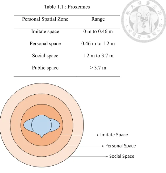
is the first property and the discussed term in this issue. In this term, we mainly focus on the spatial relationship between human and robot. How to construct a human model becomes one of the main problems. Here, an important theory named “Proxemics” is used into robotics. Proposed by Hall [3], “Proxemics” defines the four spatial regions based on the distance from a person shown in Table 1 and the illustration is shown in Figure 1.1.
Table 1.1 : Proxemics
Personal Spatial Zone Range Imitate space 0 m to 0.46 m Personal space
Social space Public space
0.46 m to 1.2 m 1.2 m to 3.7 m
> 3.7 m
Figure 1.1. Proxemics Theory of Different Spatial Intervals.
Each spatial interval performs different functional capability during human-human interaction (HHI) and this becomes a way for robot to model the spatial relationship between itself and human.
With this concept, several approaches are proposed. Pacchierotti et al. [4] defined several control strategies based on the rule of Proxemics to navigate in a hallway. They mainly focus on the problem of passage of a person and came up the solution that the robot maintains the optimal social situation with respect to the speed, the signaling
distance and the lateral distance during a passage maneuver. Lam et al. [5] proposed six kinds of Human-Centered Sensitive Field (HCSF) extended from Proxemics which consider both sensitive zones of robot and human. Not only a circle but an egg-shape were defined in HCSF that performs the different effects between the front and rear of a human. By combining the concept of Nearness Diagram [6] and HCSF, they proposed a human-friendly robot navigation framework. Kessler et al. [7] considered another situation that robot approaches a person from the front in a socially acceptable manner.
To formularize the personal space, a modified Gaussian function is defined relative to the upper body orientation called intrusion function. They then used a standard Dynamic Window Approach (DWA) method in order to control robot motion. Luber et al. [8] start from a top-view image database on the intersection to analyze the relative distance between two walking pedestrians. Using an unsupervised learning method, they generate a socially-aware path that is based on dynamic cost maps and outperforms a Proxemics- based method. In the result, they also point out that the static spatial model would sometimes cause the unnecessary detours. Chi et al. [9] proposed a 2-D pedestrian discomfort function considering position, moving direction, velocity, height, width of individual and the density of pedestrians. To unify the value of discomfort and collision risk, a Comfort and Collision Risk (CCR) map is proposed. Finally, a human-friendly robot navigation is achieved. Bellarbi et al. [10] combine the concept of personal space and social rules together to form a social navigation system. In Pandey and Alami [11], they list the general social rules and apply an egg-shaped personal space model to system.
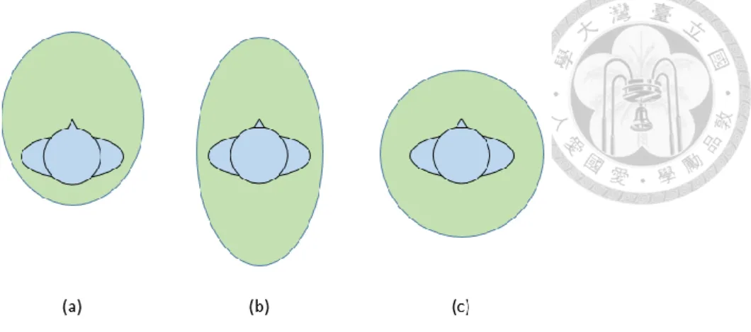
An example of different shapes of personal space is shown in Figure 1.2 below.
Figure 1.2. Different shapes of personal space. (a) ~ (c) are egg-shaped, ellipse-shaped and circle, respectively.
Liu et al. [12] proposed an online verification approach to predict a future collision based on the current observation of pedestrian velocity and position for robot to avoid. In their work, they pointed out the disadvantage of the Proxemics-based method that fixed distance would cause degrading performance of navigating in population by conservative obstacle model. Instead of that, they use the information of pedestrian velocity and acceleration to predict future position which can reduce the possible area human would occupy.
Approaches based on Proxemics enhance human comfort by not treating human as static obstacles. By interpreting the spatial relationship around human, Proxemics-based methods construct an individual human model with different coefficients that end up in different shapes. Though these works successfully take human feeling into consideration, there still remain some challenges such like the static spatial model problem mentioned in [2] and the model for an individual rather than a group of pedestrians.
1.2.2 Natural Motions
Both “Naturalness” and “Sociability” enhance the humanity of a robot. In the field
of “Naturalness”, researches focus on how to imitate human motion or walking path smoothly. By following the image of human motions, a robot navigation can be more predictable and understandable. Since Helbing [1] proposed the Social Force Model (SFM), which describes the interaction between objects or the attractive effects, lots of works have followed the concept to match the social situation during navigation. The SFM usually include the attractive force that makes agent go toward its goal, the repulsive force from other agents and the repulsive force from static obstacles. the details of SFM would be discuss in Chapter 2 later.
Tamura et al. [13] realized a smooth collision avoidance by estimating pedestrian behavior. They predict the pedestrian’s intention of avoiding behavior based on the observed trajectory modeled by the SFM. The probabilities that a pedestrian performs an (un)avoidance behavior are defined by the shortest relative distance of robot positon and these behavior trajectories. By the likelihood of avoidance, robot decides its behavior to solve the situation. Zanlungo et al. [14] proposed an approach that the pedestrians predict the collision time and position by introducing a new specification of the SFM. Compared with the original one, the proposed specifications take pedestrian’s velocity and relative distance into account and construct a new model that tries to compute the collision time in future. Ferrer et al. [15, 17, 18] proposed several works based on the SFM. [15] focuses on robot companion such as walking side-by-side. They use a Bayesian predictor to calculate the posteriori probabilities of a person’s destinations. By using the intentionality prediction, robot can infer the destination of target human which can be the attractive force of robot. They also use an Interactive Learning scheme [16] that learns the parameters of the SFM. [17] use the Bayesian Human Motion Intentionality Predictor (BHMIP) to predict the social situation nearby robot and formulize the interaction by
calculates the social forces from human and obstacles. Then, the robot can navigate in a reactive and social way in crowded environments. [18] proposed a proactive navigation approach such that robot can act in a suitable way to minimize the impact on nearby pedestrians. They take the dynamic and non-holonomic constraint into account to match the realistic situation in navigation. With the modified Social Force Model employed from [15], they model the human and robot as free 2-D particles. Rather than reacting to social situation, the robot is proactive in changing its motion initially to yield people moving around. Dewantara [19] proposed a learning-based robot navigation in multi-human environment using SFM. Instead of fixed parameters, this approach selects adaptively them by applying a learning framework named Q-learning based Social Force Navigation Model (QL-SFNM) to react to the social situation. The reward function is designed to achieve the goal, minimize the traveling distance and maximize the desired speed.
These methods based on SFM constructed the individual human model for robot to imitate or react to. But these methods are only applied to a non-holonomic system and seldom discuss about the effect of holonomic motions. The robot performs a partial human-like navigation and the result can be improved by considering the human motion consist of non-holonomic and holonomic movement.
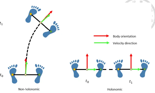
Figure 1.3. Illustrations of Non-holonomic and Holonomic Motion of Human.
On the other hand, human motion is mostly modeled as a non-holonomic system by previous works for robot to imitate. However, in some emergency situations, human would act as a holonomic system to avoid other objects. Although the non-holonomic motions are performed by human in most of time, the holonomic movements are much valuable in the narrow or complicated environment. This phenomenon has been studied by sociology researches [20 - 22] for years. Mombaur et al. [20] discuss the principles of the nature locomotion of human which consists of non-holonomic and holonomic motion.
Based on the knowledge of principles, they unify these two motions by using an optimal control system. In this work, they pointed out that the holonomic motions, such as sidestepping and oblique step, should be used in some specific situations. Hughes et al.
[21] proposed a holonomic collision avoidance algorithm for crowd simulation. By using the motion capture system, they studied the experiments that show how a human would navigate in some specific situations. From the experiments, they also concluded that the
holonomic motion would outperform in a constrained situation, such as narrow or crowed environment. Truong et al. [22] also built up a Motion library by using MotionAnalysis motion capture to record the locomotion patterns including both types of motion, the non- holonomic and holonomic behavior. Instead of modeling human on a 2D plane, they expand their control space into a 3D system which is composed of tangential, angular and lateral velocities. With the 3D system which can perform both types of motion, they can generate a human-like locomotion. Yang et al. [23] studied the acceptance of holonomic motion in the specific situation that robot and people are interacting inside a roughly space.
While robot is interacting with people, it does a little adjustment to maintain an optimal position. They compared the difference between non-holonomic and holonomic motion applied in this study. Feedback form participants shows that holonomic movement is more socially acceptable than another. This work also shows that the strong navigating ability of a holonomic system performs well during the interaction with people. Khelloufi et al.
[24] proposed a tentacle-based obstacle avoidance method with a omnidirectional mobile robot. By setting up several tentacles in different curves, they predict the future collisions and choose a safe path for robot to navigate. They show the advantages of a holonomic system during navigation. However, they do not construct a human model to distinguish people and objects.
Form these studies, a non-holonomic system is not enough to deal with a complicated situation and is a partial human-like walking motion. In that case, a holonomic system should be introduced into robot navigation to achieve naturalness.
However, there is another problem arise in the application of SFM in the holonomic system. The observations and details are discussed in Chapter 3.
1.2.3 Behavior of Sociability
In “Sociability”, the goal is to follow the social norms or human habits that makes robot be easily acceptable to society and culture. There are all kinds of social norms and habits, such like eyes-contact and pass-on-the-right, to be studied by psychology and sociology. In this field, the social signal [25 - 28] has also been studied as an important cue for human or robot to interpret the interactions. Rios-Martinez et al. [28] surveyed several works related to socially-aware robot navigation which tended to increase robot’s social abilities. They summarized the relationship between robot behavior and social signals that different social cues generated by behaviors would perform lots of different social signals. By the transition of signals, a non-verbal communication can be achieved.
Here, we are going to discuss several works and mainly focus on the human behavior during interaction in a group.
During human-human interaction, there may be some situations that social rules are violated; however, the rules of “Comfort” and “Naturalness” are not. In [2], the surveys of sociability [7, 29- 32] concluded that the violation of a social rule would cause this discomfort rather than a violation of a comfort distance. Therefore, there are several approaches focus on modeling social rules or norms into navigation framework. Chen et al. [33] proposed a deep learning-based approach that introduced social rules into a reward function. Instead of what to do, they considered about specifying what not to do, such as avoiding the overtaking, passing and crossing in some situations. By using a symmetric multi-agent network with a sharing weight matrix, the system products an optimal policy based on the states of agents nearby robot. Khambhaita et al. [34] focus on the gazing problem. A robot could use its gazing direction to perform the social attention such like robot is awared of a human or just focus on the traveling path. They
human, which communicate with human by social signals.
Table 1.2 : F-formation
Spatial interval functionality o-space Information exchanging
p-space Human standing and
gesture performing
R-space Public space
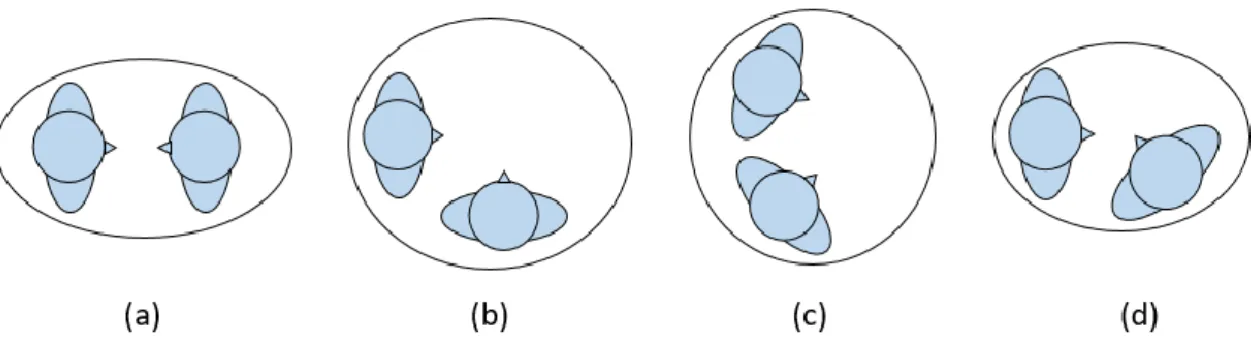
While human is interacting with others, we usually form a group rather than individual. The concept of “F-formation” proposed by Ciolek et al. [35] from sociology was introduced into robotics. They defined the grouping space as three intervals: o-space, p-space and R-space. This concept describes the situation that human is dynamically standing inside the group space. Table 2 lists the details of each interval and Figure 1.4 shows the example of the F-formation patterns.
Figure 1.4. The examples of the F-formation patterns. (a) ~ (d) are Vis-à-vis, L-shaped, C-shaped and V-shaped, respectively.
Rios-Martinez et al. [36] proposed a risk-based navigation which use the concept of F-formation to model human-human interaction and then apply into risk-RRT algorithm.
By the grouping model, robot would avoid to pass the space between people who belongs to a group. [23] also uses this concept to form the socially acceptable navigation during human-robot interaction. In their work, robot is interacting with standing people and tries to maintain its optimal position inside the p-space which represents that robot is participating the group.
There are still other methods that formulize the grouping space. Vega-Magro et al.
[37] first construct individual model by a Gaussian function considering human orientation. Then, they modeled people into groups by summing the Gaussian value of each grid in global map and put it into the RRT path planner. Truong et al. [38] proposed a human comfortable safety navigation based on the dynamic social zone (DSZ) which represents the social interaction space around a person, a group or human-object situation.
The DSZ is actually extended from F-formation to explain different situations.
These methods focus on modeling a group that stands inside an area. By the concept of F-formation, robot can read the social situation and follow the social rule, such as not pass between two interacting people. Although they successfully explain several social situations, there still remains the challenge to model the walking behavior of a group.
1.3 Objectives
Based on the description above, the overall objective of this thesis is to propose a socially-aware robot navigation with an omnidirectional extended Social Force Model and the dynamic group model. The descriptions of objective are shown below.
Develop an extended Social Force Model to a holonomic mobile system
Although the non-holonomic mobile robot is widely applied in the field of navigation, it still suffers from the weaker ability of avoidance due to the sliding constraint. In contrast, a holonomic mobile system that can perform a strong navigational ability and imitate human motions is used in this thesis. However, because of the holonomic property, the system cannot apply the traditional Social Force Model directly. A holonomic mobile robot driven by the SFM would navigate without rotating its orientation. Therefore, we propose an extended Social Force Model including a rotational social force that describes the orientation of an omnidirectional robot. By this force, the robot can perform holonomic motions while imitating a human-like rotation.
Construct a dynamic grouping model based on the pedestrian behavior
In the previous work on human modelling, most of them construct the individual model based on Proxemics or SFM, and it is hard to use them to explain the pedestrian behavior in groups. Even there are several works focus on modelling the groups, some existing works construct the grouping model based on F-formation or other assumptions in a static state. The lack of dynamic grouping model which describes the behavior and state in motion becomes the problem. In this thesis, based on the sociology researches of crowds, we propose a dynamic grouping model that categorizes individuals into groups and calculate the properties of group including the width, moving direction, velocity, an interacting factor. This information can be seen as the social situation that describes not only individual but also group behaviors. By introducing this model into our system, the robot can perform a socially-aware navigation that acts corresponding to the interactions in group.
1.4 Thesis Organization
This these is organized as follows. In Chapter 2, we introduce the hardware design of our omnidirectional robot including the holonomic kinematic, some background knowledge of human tracking system and social norms. In Chapter 3, the proposed socially-aware navigation using extended social force model (EFSM) is presented. With the grouping human model and ESFM, several robot behaviors are designed. In the end of Chapter 3, a multi-policy decision making procedure is proposed. In Chapter 4, the experiments show the interacting detection and the result of robot behaviors. We implement the system on an omnidirectional mobile robot and evaluate the effects through the real interaction with human. Finally, Chapter 5 gives the summaries, conclusions and future works.
Chapter 2
Preliminaries
2.1 Omnidirectional Mobile Robot
In this section we introduce the design and several important kinematics of omnidirectional mobile robot using in this work. To imitate human movement, which is actually a hybrid system of non-holonomic and holonomic movement, a three-wheels mobile robot was designed and used. With the characteristic of omnidirectional movement, a nature and human-like navigation is possible.
2.1.1 Hardware Design
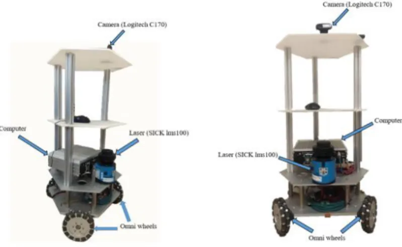
The following shows the architecture of our omnidirectional mobile robot. Hardware design is shown in Figure 2.1.
Figure 2.1. Hardware Design of Omnidirectional Mobile Robot
Figure 2.2. Example of a omnidiretional wheel.
This mobile robot is hexagonal shape, there are three wheels, one laser range finder, one camera mounted on it. This wheel with several sliding wheels, shown in Figure 2.2, can let robot has the ability to do a lateral movement. The wheels divide equally the plane, which means each angle between two adjacent axis of wheel is 120 .
Figure 2.3. The Hardware Structure of A Three Omnidirectional Wheels Mobile Robot.
For mobile robot moving on the ground, the maximum degree of freedom is three,
which include translation along x-axis, y-axis and rotation about z-axis. Therefore, the pose of a mobile platform can be written as
x y
T . Corresponding to that, the control input of the platform is
vT vL
T which are tangential velocity, lateral velocity and angular velocity respectively.Figure 2.4. Kinematic Model of Holonomic Mobile Robot.
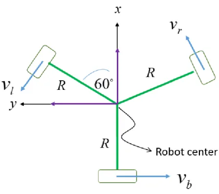
The model of this robot structure is shown in Figure 2.3 above. Wheel’s velocities are symbolled as vl, vr, vb, which is left, right, back wheel, respectively. With variable R as radius, as the angle between direction of vl and vr, the mathematic model can be written as equation below.
[ 𝑣𝑙 𝑣𝑏 𝑣𝑟
] = [
−𝑠𝑖𝑛60° 𝑐𝑜𝑠60° 𝑅
−sin(𝛼 + 60°) 𝑐𝑜𝑠(𝛼 + 60°) 𝑅
−sin(𝛼 − 60°) 𝑐𝑜𝑠(𝛼 + 60°) 𝑅 ] [
𝑣𝑇 𝑣𝐿 𝜔
] (2.)
For the sensing ability, a Laser Range Finder(LRF), SICK LMS100, and a web camera, Logitech c170, are used. The LRF, which is mounted at height, is able to detect
obstacles and human legs. The scanning rate is up to 50Hz and the operating range is from 20cm to 20m. This property is enough for indoor environment, even a square. The field of view is 270 and the resolution is 5 . The laser data are expressed into a set as:
laser n
n
n d n N
P
P
, (2.)
where dn is the measurement and n is the angle in n laser beam, th Nlaser is the number of total laser data. These sequence laser point can be used as geometrical feature for modeling the environment.
2.1.2 Omnidirectional Movement
Different from differential movement, omnidirectional movement, or says holonomic movement, does not suffer from sliding constraint – no sliding motion.
Because of the special mechanism, robot is allowed to have lateral velocity with rotating about z-axis simultaneously. Such property makes robot has a higher ability in navigation.
The holonomic model can be expressed as:
sin0 cos0 10 L 0 sin cos
v v y
x T
(2.)
With different combinations of control input
vT vL
T , several holonomic movements can be achieved. With zero angular velocity, lateral and diagonal movementThe control input can be expressed as equation below.
0 0
,desire L L T
v v v
(2.)
The diagonal movement is a combination of tangential and lateral velocity. Without changing the heading, robot could move forward to a diagonal direction. The control input can be written as:
0
, ,
desire L
desire T L T
v v v v
(2.)
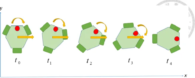
On the other hand, with a value of angular velocity, robot can achieve a powerful movement called “rotating without changing transition direction”. While rotating the heading angle, robot can move toward a fixed direction in global coordinate simultaneously. From study of human motion, this movement is the most useful and common when we are going to turn and move forward in the same time. As observation, the translational direction is relative to global coordinate. If the global translational and angular velocity
x y
are given. The control input can be written as:
y x v
v
L T
1 0 0
0 cos sin
0 sin
cos (2.)
An example of this movement is illustrated in Figure 2.5.
Figure 2.5. Rotation without Changing Translation Direction.
By these holonomic movements, robot can move in a more nature, human-like way.
Besides, robot has a powerful ability to avoid obstacles in high density or narrow environment.
2.2 Human Tracking System
In this section we describe the human tracking system by using laser range finder and web camera. Human tracking system is composed of two part: (1) human detection, (2) human tracking. In this work, laser range finder is used to detect the human position which is the input of the tracking system. On the other hand, human information
2.2.1 Human Detection and Tracking
Human detection using laser has been studied in Human Robot Interaction and navigation for years. Several works are proposed in literature. These methods are designed to detect legs or bodies and can be track by a laser-based system. Recall the laser
distinguished from the data. Some important geometry features are described in [39].
Referring from our previous work, a modified “inscribed angle variance” (IAV) [40]
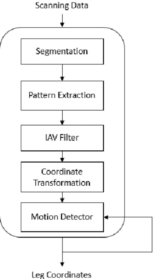
method is proposed for human detection which studied the leg’s patterns. The flow chart of hybrid approach to human detection is shown in Figure 2.6.
Figure 2.6. Flow Chart of Human Detection System
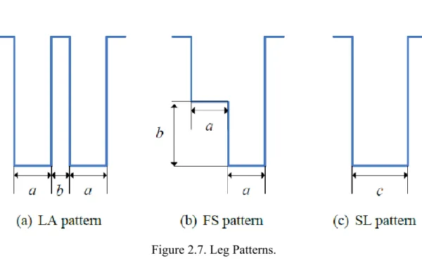
The hybrid approach can be decomposed into five parts: segmentation, pattern extraction, IAV filter, coordinate transformation and motion detection. After a sequence of laser scanning data is collected by laser range finder, the measured points are clustered into several sub-group based on the Euclidean distance between two adjacent points. To distinguish whether these segments are legs or not, several leg patterns are used to match the geometry traits. In Figure 2.7, three patterns using in this work are illustrated which
are LA (legs apart) pattern, FS (front straddle) pattern and SL (legs together) pattern.
However, these patterns can be generated by some false positive such like chairs or electric fan. To overcome this problem, a modified IAV method is used. With the specific range and arc shape of human leg, this method can separate human legs and other objects.
After that, human position is calculated from these segments by doing coordinate transformation. In the end, a motion detector will sense a human is moving or not. Thus, the output of the detection system would be the position and moving information of all human in robot’s the field of view.
Figure 2.7. Leg Patterns.
As the detection procedure finished, a Sequence Importance Resampling (SIR) particle filter based human tracking system is introduced [41]. For predicting human which includes position and velocity, the human state is presented in a probability model 𝑝(𝑥𝑡|𝑥𝑡−1). The prediction model based on the assumption of constant velocity can be modeled as:
) sin(
) cos(
1 1
1 1
1
1 1
1 t
v t t
t t
t t
t t
t t
t
n v v
n T v y y
T v x x
(2.)
Where T is the time interval, 𝑛𝜃 and 𝑛𝑣 are the Gaussian noises with zero mean and constant covariance. For the update stage, a distance model considered as a measurement model can be expressed as:
𝑝(𝑧𝑡|𝑥𝑡) = (√2𝜋𝜎)−1𝑒𝑥𝑝(− 𝑑𝑖
2𝜎)2 (2.)
Where 𝑑𝑖 is the distance between the 𝑖𝑡ℎ particle state and estimated pose. In the weighting update step, the posterior distribution function (PDF) of human state can be approximated by a set of weighted particles. Finally, the human state [𝑥𝑡 𝑦𝑡 𝜃𝑡 𝑣𝑡] can be estimated by the weighted mean of all the particles.
Figure 2.8. Laser-Based Leg Detection Example.
2.2.2 Human Skeleton Keypoints Estimation
Although laser measurement is an efficient way to have an accurate information of distance, other information of human such like heading angle or posture is hard to obtain.
From sociology research and observation, human could face to a direction different from moving direction. This human motion characteristic is far difference from the assumption of previous works and cannot calculate from SIR tracking system directly. Therefore, a visual-based skeleton detection system is used in our work.
Cao et al. [42] proposed a real-time multi-person pose estimation method, named OpenPose, that can detect human skeleton using RGB images. This work is the first bottom-up representation of association scores via Part Affinity Fields (PAFs). PAFs is a set of 2D vector fields that encode the degree of association between parts of human body in the image domain. Taking a color image of size 𝑤 × ℎ, the system produces the 2D locations of keypoints for each person in the image. The input image is first analyzed by a convolutional network which is initialized by the first 10 layer of VGG-19[43] and fine- tuned to generate a set of feature maps F. These feature maps are then put into a feedforward network to predict a set of 2D confidence maps 𝑆 of body locations and a set of 2D vector fields 𝐿 of part affinities, simultaneously. Finally, the confidence maps and the affinity fields are parsed by greedy inference to output the 2D keypoints representing the joint positions for all people in the image. The system flow is shown in Figure 2.9 below.
Figure 2.9. System flow of multi-person pose estimation method.
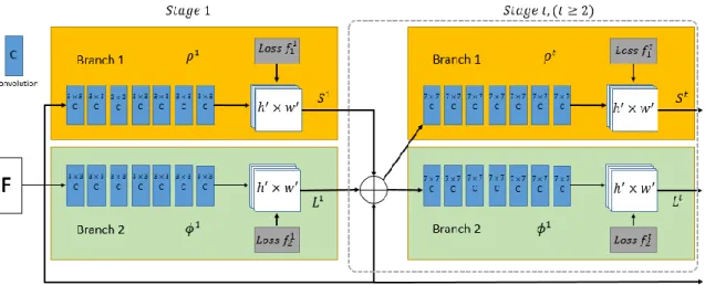
This method uses a two-branch Convolutional Neural Network (CNN) to predict confidence maps 𝑆𝑡 and part affinity fields 𝐿𝑡, respectively. Each branch is an iterative prediction architecture concatenated for next stage along with the image features, shown in Figure 2.10. The upper branch predicts confidence maps 𝑆𝑡 and the bottom one predicts PAFs 𝐿𝑡.
Figure 2.10. Architecture of The Two-Branch Multi-Stage CNN.
After the prediction and detection of human in the image, a list of 2D keypoints obtained from the CNN network can be regarded as a useful information of human orientation and facing direction. The example is shown in Figure 2.11 below.
Figure 2.11. Example of the keypoints of a person.
Here, the domain of keypoints can be represented as:
𝐷𝑜𝑚𝑎𝑖𝑛𝐾𝑃 = {𝑝0, 𝑝1, 𝑝2, … , 𝑝17} (2.) 𝑝𝑖 = [𝑥𝑖𝑖𝑚𝑔 𝑦𝑖𝑖𝑚𝑔], ∀𝑝𝑖 ∈ 𝐷𝑜𝑚𝑎𝑖𝑛𝐾𝑃 (2.)
In detail, {𝑝0, 𝑝14, 𝑝15, 𝑝16, 𝑝17} are the points of nose, eyes and ears, respectively.
{𝑝1, 𝑝2, 𝑝5} are shoulders; {𝑝3, 𝑝4, 𝑝6, 𝑝7} are arms. We then focus on these points to calculate the human orientation. The methodology would be described in Chapter 3.
2.3 Social Force Model
Helbing et al. [1] proposed the basic idea of Social Force between interactions in late 20th century. It is based on the concept of changing in behavior which can be explained in terms of social forces or potential fields. These social force can be
objects based on the type of interaction.
An attractive force describes the moving intention of an agent. Let 𝑛𝑎𝑖→𝑔𝑖 be the unit vector for the agent 𝑖 toward its goal and 𝑘𝑎 is the parameter representing the strength of force. The attractive force can be expressed as:
𝑓𝑖𝑎𝑡𝑡𝑟 = 𝑘𝑎 ∙ 𝑛𝑖→𝑔𝑖 (2.)
Second, the repulsive force describes the interaction between an agent 𝑖 and another agent 𝑗 that prevents from collision can be modeled as:
𝑓𝑖,𝑗𝑖𝑛𝑡 = 𝛼𝑝exp(−𝑑𝑖,𝑗
𝛽𝑝) ∙ 𝑛𝑗→𝑖 (2.)
where {𝛼𝑝 𝛽𝑝} are the SFM parameters for human, 𝑑𝑖,𝑗 is the distance between these two agents and 𝑛𝑗→𝑖 is the unit vector from agent 𝑗 to 𝑖.
Similarly to the previous one, the repulsive force between an agent 𝑖 and an obstacle 𝑜 ∈ 𝑂 in the neighborhood of 𝑖 with different SFM parameters {𝛼𝑜 𝛽𝑜} and unit vector 𝑛𝑜→𝑖 can be modeled as:
𝑓𝑖,𝑜𝑜𝑏𝑠 = 𝛼𝑜exp(−𝑑𝑖,𝑜
𝛽𝑜) ∙ 𝑛𝑜→𝑖 (2.)
Finally, the resultant force is the summation of all exerted forces. For an agent 𝑖, the overall social force can be expressed as:
𝑓𝑖 = 𝑓𝑖𝑎𝑡𝑡𝑟+ ∑ 𝑓𝑖,𝑗𝑖𝑛𝑡
𝑗≠𝑖
+ ∑ 𝑓𝑖,𝑜𝑜𝑏𝑠
𝑜∈𝑂
(2.)
An illustration of a Social Force Model is shown in Figure 2.12.
Figure 2.12. The illustration of social force model. (a) shows the example that two agents and a wall are performed. Green arrow is the repulsive force and red is the attractive one.
The overall social force 𝐹𝑖 is shown in (b).
2.4 Gap Analyzing
Borrowing the concept from Nearness-Diagram proposed by Minguez and Montano [6] and the previous work from our lab [5], a laser-based gap analyzing method is used.
Figure 2.13. Regions obtained from gap analyzing.
From the laser data P = {𝑃𝑛 = [𝑑𝑛 𝜙𝑛]𝑇}, 𝑛 ∈ 𝑁𝑙𝑎𝑠𝑒𝑟 , we first calculate the Euclidean distance between two adjacent points. With the threshold 𝐺𝑎𝑝𝑡ℎ𝑟𝑒 , we can clutter the laser points into several groups, some of them are human and the remaining are environmental obstacles. A list of gaps 𝐺𝑎𝑝̂ is built after this procedure.
Gap occurs when the Euclidean distance between two adjacent points exceeds the threshold 𝐺𝑎𝑝𝑡ℎ𝑟𝑒. The formula is:
|𝑑𝑖− 𝑑𝑖−1| > 𝐺𝑎𝑝𝑡ℎ𝑟𝑒, 𝐺𝑎𝑝𝑡ℎ𝑟𝑒 > 0 (2.)
There are two types of edge that form the starting and ending of a gap named 𝐸𝑑𝑔𝑒𝑟𝑖𝑠𝑖𝑛𝑔 and 𝐸𝑑𝑔𝑒𝑓𝑎𝑙𝑙𝑖𝑛𝑔 are defined as below:
𝐸𝑑𝑔𝑒𝑟𝑖𝑠𝑖𝑛𝑔 = {𝐸(𝑑𝑖, 𝑑𝑖−1)| 𝑑𝑖 − 𝑑𝑖−1 > 𝐺𝑎𝑝𝑡ℎ𝑟𝑒} () 𝐸𝑑𝑔𝑒𝑓𝑎𝑙𝑙𝑖𝑛𝑔= {𝐸(𝑑𝑖, 𝑑𝑖−1)| 𝑑𝑖−1− 𝑑𝑖 > 𝐺𝑎𝑝𝑡ℎ𝑟𝑒} ()
An example illustrate the environment and result of gap analyzing is shown in Figure 2.13 above. A rising edge E(𝑃𝑎, 𝑃𝑎−1) and a falling edge E(𝑃𝑏+1, 𝑃𝑏) can form an area Γ𝑖 = [𝜙𝑠𝑡𝑎𝑟𝑡, 𝜙𝑒𝑛𝑑]𝑇 that describes the gap and free space, where .𝜙𝑠𝑡𝑎𝑟𝑡 and 𝜙𝑒𝑛𝑑 are the starting and end angle of the 𝑖𝑡ℎ region, respectively. After all the possible gaps are calculated, a list of gap 𝐺𝑎𝑝̂ can be obtained. The regions are Γ1 = [𝜙𝑎, 𝜙𝑏]𝑇 , Γ2 = [𝜙𝑐, 𝜙𝑑]𝑇 and Γ3 = [𝜙𝑒, 𝜙𝑓]𝑇.
2.5 Multi-Policy Decision Making
A decision making problem has been studied for decades and applied to lots of robot frameworks. Here, we apply the work proposed by Mehta et al. [44], the Multi-Policy Decision Making (MPDM) method. Given a set of policies 𝛏, observation z, the joint state of robot and detected human x, the MPDM would simulate the joint state forward for each executable policy and product an optimal policy based on the cost function. In this section, we first describe the cost function and then the body of MPDM.
2.5.1 Multi-Policy Decision Making
In the decision making procedure, [44] first define a function that simulates the joint state forward in a given time interval. Given the joint state and one policy, the function named simulate_forward calculates the future trajectories of human and robot and the total cost during the time interval.
Algorithm MPDM(𝐱, 𝐳, 𝒕𝑯, 𝑵𝒔) 1. for 𝝃′ ∈ 𝝃 do
2. for 𝐬 = 𝟏, … , 𝑵𝒔 do 3. 𝒙𝒔~𝑷(𝒙|𝒛)
4. 𝐂(𝒙𝒔, 𝝃′) = simulate_forward(𝒙𝒔, 𝝃′, 𝒕𝑯) 5. end for
6. end for
7. return 𝝃∗ = 𝒂𝒓𝒈𝒎𝒊𝒏𝝃′(𝑬𝒙{𝑪(𝒙, 𝝃′)})
The body of MPDM is shown in Algorithm above. Given current observation form sensor, we first sample 𝑁𝑠 times of the joint state from the observation. Each sample is simulated forward by the function simulate_forward with a policy and a given time interval 𝑡𝐻 . The cost of each turns would be the feedback of the simulate_forward function and an expectation method is used to calculate the mean state of the cost with considering the uncertainties. To obtain a closed form of the cost expectation, a sample technique, importance sampling, is used. The approximation of the expectation can be expressed as:
𝐸𝑥{𝐶(𝒙, 𝜉)}~ ∑ 𝑤𝑠𝐶(𝑥𝑠, 𝜉)
𝑠∈𝑆
(2.)
where S is the set of samples drawn from the distribution 𝑃(𝑥|𝑧) and 𝑤𝑠 is the importance weight. These samples would result in the different future trajectories that take the uncertainty into account. The simulate_forward function is shown in Algorithm below.
Algorithm simulate_forward(𝐱, 𝛏, 𝒕𝑯) 1. .𝑿̂ = {}
2. for 𝒕′= 𝒕, 𝒕 + ∆𝒕, … , 𝒕𝑯do 3. 𝒙̂̇𝒓(𝒕′) = 𝒇𝒓(𝒙(𝒕′), 𝝃)
4. 𝒙̂𝒓(𝒕′+ 𝚫𝒕) = 𝒙̂𝒓(𝒕′) + ∫𝚫𝒕𝒙̂̇𝒓(𝝉)𝒅𝝉 5. for 𝐢 ∈ 𝟏, … , 𝐫 − 𝟏, 𝐫 + 𝟏, … , 𝐍 do 6. 𝒙̂̇𝒊(𝒕′) = 𝒇𝒊(𝒙(𝒕′), 𝑮𝒐 − 𝑭𝒐𝒓𝒘𝒂𝒓𝒅) 7. 𝒙̂𝒊(𝒕′+ 𝚫𝒕) = 𝒙̂𝒊(𝒕′) + ∫𝚫𝒕𝒙̂̇𝒊(𝝉)𝒅𝝉 8. end for
9. 𝒙̂(𝒕′+ 𝚫𝒕) = {𝒙𝟏(𝒕′+ 𝚫𝐭), … , 𝒙𝑵(𝒕′+ 𝚫𝐭)}
10. 𝑿̂. 𝒂𝒑𝒑𝒆𝒏𝒅(𝒙̂(𝒕′+ 𝚫𝒕)) 11. .end for
12. 𝐂 = −𝛚𝐏𝐆(𝑿̂) + 𝐅(𝑿̂) 13. .return 𝐂
2.5.2 The Cost Function
As the general purposes of design the cost function, there are two main goal of a robot navigation, progress toward its target position and avoid to disturb the human or collide to an obstacle. The two components of the cost function are:
Force: The summation of maximum repulsive force exerted on another agent can be regarded as the cost of disturbing others. The cost can be expressed as:
F (𝑋̂(ξ)) = ∑ 𝑚𝑎𝑥𝑗≠𝑟‖𝑓𝑟,𝑗𝑖𝑛𝑡(𝑥̂(𝑡′, 𝜉))‖
𝑡𝐻 𝑡′=𝑡
(2.)
Progress: The term encourages the robot for going toward the goal. With the unit vector 𝑛𝑟→𝑔𝑟 toward its goal and a future position applying a policy 𝑥𝑟(𝑡𝐻, 𝜉), the cost of progress can be expressed as:
PG (𝑋̂(ξ)) = (𝑥𝑟(𝑡𝐻, ξ) − 𝑥𝑟) ⋅ 𝑛𝑟→𝑔𝑟 (2.)
Chapter 3
Socially-Aware Navigation
3.1 System Architecture
The overview of our system is shown in Figure 3.1. From the multi-human indoor environment, the robot will operate in a proper action and movement based on the current situation which can be described by the state of human and obstacles. Each control loop starts from sensing module, which combines a laser-based submodule with a vision-based one, and collects data including human information and obstacles position. About the second stage, we are going to construct models of human and static obstacles from the collected data. After modeling the environment, the main procedure of decision making is applied. This multi-policy decision making procedure will choose an optimal policy that matches the social situation that the robot is currently facing. Recall that the velocities controlled by the system behind are translation along x-axis, y-axis and rotation about z- axis, namely [𝑣𝑇 𝑣𝐿 𝜔]𝑇 , the control module perform to send proper velocity command to actuators. Following the optimal policy, the robot navigates in the environment by controlling the robot’s behaved velocities to achieve socially-aware navigation. The description of each function modules is shown below.
In the sensing module block, it is composed of laser-based and vision-based models. For laser-based model, we collect the laser data as geometry feature such as distance and angle. For vision-based model, we use the multi-person
2D keypoints detection method proposed by [42] to calculate human heading direction. The detail is described in Chapter 2.
Figure 3.1. Overall system architecture.
In the human detection module, we use the sensing data to construct individual human model and go one step further to construct group model from it. This individual and group models together will be considered as the social situation faced by the robot. After the construction, this information will form a joint state of robot and pedestrian which will be a part of decision input.
For other static obstacles in the environment, such as wall, sofa, chair, we can also collect the geometry data from laser. Here, we use the idea of gap analysis [6]. This method clusters the laser data into several groups based on the Euclidean distance between two adjacent laser points. From the analysis, a sequence of gaps is confirmed and describes the free space of the robot configuration. After clustering, we also do the line detection to figure out where a wall is. The detail is described in Chapter 2.
The policy set consists of several policies, also known as robot behaviors, including “Go-Forward”, “Follow Agent”, “Wall Following”, “Stop”. Actually, the size of executable policy list is dynamic because the number of agents who can be followed is yet to be determined. Therefore, this module also takes human states as input to construct the current policy set.
In Multi-Policy Decision Making module, we take the human model, gaps, and a list of executable policies into consideration. First, this module does sampling from the current observation of joint state. Second, it simulates all the agents including human and robot forward time for some duration with the executable policies and the calculate the total cost of each individual policy. Based on the cost, an optimal one is chosen by this decision making procedure for the robot to execute. The submodule of this procedure is shown in Figure 3.2.
As has been described in Chapter 2, the control module is composed of robot
control and actuator model. Robot control model follow the optimal policy ξ𝑜𝑝𝑡𝑖𝑚𝑎𝑙 to generate the velocity [𝑣𝑇 𝑣𝐿 𝜔] . The actuator model then generates the output velocity [𝑣𝑙 𝑣𝑟 𝑣𝑏] to each wheel. The hardware design and system detail can be seen in Chapter 2 as well.
3.2 Human Model Construction
To achieve a socially-aware navigation, we take human feeling and nature into consideration. We first define an individual model which represents a human with several assisting information including position, orientation, and velocity. Constructed from sensing data, this individual model can express the human trajectory and behavior that become the social cues. Different from previous works, we go one step further to construct the group model that describes the dynamics and behavior of a crowd. The behavior between pedestrians in a group can give us more information about human crowds. In the real environment, pedestrians walk either in individual way or with others to form a group.
Following this concept, we propose a human model including individual and dynamic group model that show the social situation surrounding the robot.
3.2.1 Individual Model Construction
To construct an individual human model, we first define the component of this model.
The information of an individual model includes position, orientation, and velocity. The model can be written as:
ℎ = [𝑝𝑥 𝑝𝑦 𝜃 𝑣𝑥 𝑣𝑦] (3.)
As mentioned in Chapter 2, we can get the information of position and velocity from laser data. Extracting the geometry features from laser points, we first detect human legs and calculate the position. Afterward, a SIR particle filter is used to predict human state and calculate human velocity. In this subsection, we focus on how to figure out human orientation.
To obtain human heading or body orientation, we utilize the multi-person pose estimation proposed by [42] to collect the keypoints of human body. A list of keypoints can be obtained from the networks and represented in image coordinate. Recalled from Chapter 2, the keypoints representing the shoulders, arms are used to calculate the human orientation. We first utilize the property that the length of arm and width of shoulder would be proportional for all human. This property can also be applicable to the situation where the proportion of human body in image is changed by the distance between RGB sensor and human. A predefined parameter 𝑅𝑎𝑡𝑖𝑜𝑤/𝑙 is the ratio of width of shoulder 𝑤𝑟𝑒𝑓 and length of arm 𝑙𝑟𝑒𝑓 in a normal situation. With this ratio, for each sampling data {𝑤′, 𝑙′} we can calculate the angle of orientation in [0, 𝜋] . The formula and illustration are shown below.
𝑅𝑎𝑡𝑖𝑜𝑤/𝑙 =𝑤𝑟𝑒𝑓
𝑙𝑟𝑒𝑓 (3.)
𝜃𝐻 = 𝑐𝑜𝑠−1( 𝑤′
𝑙′× 𝑅𝑎𝑡𝑖𝑜𝑤/𝑙) (3.)
Figure 3.3. Illustration of The Width 𝑤𝑟𝑒𝑓 And Length 𝑙𝑟𝑒𝑓.
Then, we translate the angle of orientation into [0, 2𝜋] in order to project the orientation into 2D plane. By doing this, we need to determine whether the rotation is made clockwise or counterclockwise. By the fact that the nearer arm should be longer than the farer one in image, we compare the length of both arms to figure out the rotation direction. Therefore, we get the orientation of individual projecting in 2D plane.
In general case, the calculation above is precise. However, the detection may have some noise. In order to be more robust, we use the image pixels on the head which are more stable during detection. By comparing with the distance 𝑙𝑙𝑒𝑓𝑡_𝑒𝑦𝑒 and 𝑙𝑟𝑖𝑔ℎ𝑡_𝑒𝑦𝑒 , we can distinguish the orientation into left-oriented or right-oriented. Using this information, we can avoid the situation when the key points of the arms cannot be detected.