國立臺灣大學電機資訊學院電信工程學研究所 碩士論文
Graduate Institute of Communication Engineering College of Electrical Engineering and Computer Science
National Taiwan University Master Thesis
非正交多重接取系統中之混合式自動重傳請求 Hybrid-ARQ in Non-orthogonal Multiple Access System
吳晉廷 Chin-Ting Wu
指導教授:蘇炫榮 博士 Advisor: Hsuan-Jung Su, Ph.D.
中華民國 105 年 10 月 October, 2016
致謝
在剛進研究所的時候,對於研究方向還不是很明確,在老師和學長們的幫忙下,
讓我對各種領域都有了解,並找到自己有興趣的研究題目,首先要感謝我的指導
教授蘇炫榮老師,老師總是耐心的指導,適時的對我提出研究的建議,在研究上
給了我許多幫助,也要感謝偉舜學長,就算在日本還是不厭其煩的回答我有關程
式上的問題,還有昇翰學長在這段時間內和我不斷的討論,也給我很多意見,在
我徬徨無助的時候給了我許多鼓勵和支持,也感謝實驗室的同學和學弟妹們,大
家一起玩樂,一起做研究,讓我在這段研究生涯中度過了愉快的時光,最後要感
謝我的家人以及朋友的關懷與照顧,不管我遇到甚麼挫折都是默默支持著我,讓
我的求學生涯能無後顧之憂,也讓我能順利完成論文。
吳晉廷 謹誌
2016 年 10 月
摘要
具有連續干擾消除器(SIC)的非正交多址(NOMA)是用於進一步 LTE 增強的有希
望的下行鏈路多址方案。本文研究了 NOMA 與 SIC 的系統級性能。自適應調製和編
碼方案(AMC)和混合自動重傳請求(HARQ)是鏈路自適應的兩個不可或缺的部分,
並且在現代無線通信系統中也起著非常重要的作用。 AMC 可以根據信道條件來調
整調製和編碼方案(MCS)以最大化系統吞吐量,並且 HARQ 可以通過重傳解碼失
敗的數據來提高系統可靠性和信道編碼增益。然而,在 NOMA 系統中,HARQ 比在
OMA 中具有更多的困難。在本文中,我們調查比例公平(PF)設計在重傳和新的
HARQ 設計下行鏈路 NOMA 系統。提到了用戶配對和傳輸功率分配對 NOMA 性能的影
響。另外,由於沒有實現具有固定閾值的 AMC 作為實際系統設計,我們提出了一
種根據每個傳輸輪中的 HARQ 確認(ACK)反饋信息來自適應地調整 AMC 閾值的方
法。
關鍵字: 非正交多址,干擾消除,比例公平排程,混合自動重傳請求,自適應調
製和編碼方案,閾值調整
Abstract
Non-orthogonal multiple access (NOMA) with a successive interference canceller (SIC)
is a promising downlink multiple access scheme for further LTE enhancement. This
paper investigates the system-level performance of NOMA with SIC. Adaptive
modulation and coding scheme (AMC) and hybrid automatic repeat request (HARQ)
are two indispensable parts of link adaptation, and also play very important roles in
modern wireless communication system. AMC can adjust modulation and coding
schemes (MCS) according to channel condition to maximize system throughput and
HARQ can improve system reliability and channel coding gain by retransmitting data
packet which decoded unsuccessfully. However, in NOMA system, HARQ has more
difficulties than in OMA. In this paper, we investigate proportional fairness (PF) design
in retransmission and new HARQ design for downlink NOMA system. The impacts of
user pairing and transmission power allocation on NOMA performance are mentioned.
In addition, without implementing AMC with fixed threshold as practical system design,
we propose a method to adaptively adjust the AMC thresholds according to the HARQ
acknowledge (ACK) feedback information in each transmission round.
Key word: NOMA, interference cancellation, PF scheduling, HARQ, AMC, threshold
adjustment
Content
Chap 1 Introduction……….1
1.1 Background and Motivation……….1
1.2 Contribution and Thesis Organization………..2
Chap 2 Basic Introduction and System Model………..4
2.1 Introduction to NOMA SIC……….4
2.2 System Model………..6
2.2.1 Introduction to AMC systems………...8
2.2.2 Introduction to HARQ………..9
2.3 Proportional Fair Scheduling Algorithm………10
2.3.1 Introduction to Proportional Fair Scheduling………..11
2.3.2 Exhaustive Search Proportional Fair Scheduling………12
Chap 3 New Designs for HARQ in NOMA System……….17
3.1 Difficulties of HARQ in NOMA………17
3.1.1 Retransmission Wasted………19
3.1.2 Unsuccessful Cancelation of Interference………...19
ii
3.1.3 User Re-pairing………...20
3.2 New Design for HARQ in NOMA………20
3.3 New Design of Proportional Fair Scheduling for HARQ in NOMA……….22
3.3.1 Method 1: Proportional Fair Scheduling with Expected Throughput…….23
3.3.2 Method 1: Proportional Fair Scheduling with Expected Throughput by Capacity………24
3.3.3 Simulation Result of New PF Design……….25
3.4 The Comparison of Different Aggressiveness for Far User in HARQ…………...30
Chap 4 Adaptive Threshold Adjustment Algorithm for HARQ in NOMA System………..32
4.1 Adaptive Threshold Adjustment Algorithm………...32
4.2 Adaptive Threshold Adjustment Algorithm in NOMA System………..38
4.3 Simulation Results………..38
Chap 5 Conclusions and Future Works………...42
BIBLIOGRAPHY……….44
List of Figures
2.1 Basic NOMA applying SIC receiver in downlink………...4
2.2 System model for NOMA with AMC and HARQ mechanism………...6
2.3 Illustration of AMC mechanism………..8
2.4 Example of chase combining………10
3.1 Decoding example for both users in NOMA system……….18
3.2 Throughput of different PF scheduling algorithm………28
3.3 Throughput of different PF scheduling algorithm………29
3.4 Comparison for far user using different MCS………..31
4.1 Comparison for fixed MCS threshold and AAMC………40
4.2 Comparison for fixed MCS threshold and AAMC………40
4.3 Throughput of using adjusted threshold for fixed threshold……….41
iv
List of Tables
2.1 Comparison for OMA and NOMA………..5
3.1 The information stored for HARQ chase combining………22
3.2 Parameters for simulation in NOMA system………27
3.3 Comparison for cell edge throughput between normal PF and method 1………….28
3.4 Comparison for cell edge throughput between normal PF and method 2………….28
3.5 Comparison for cell edge throughput between normal PF and method 2 without
constraint……….30
4.1 Parameters for AAMC algorithm in NOMA system……….39
Chap 1
Introduction
1.1 Background and Motivation
In recent years, the demand of mobile Internet is increasing and fifth generation
(5G) wireless systems is expected to be deployed in the 2020s[1]. Non-orthogonal
multiple access (NOMA) is one of the candidate multiple access scheme for 5G.
NOMA with successive interference canceller (SIC) receiver is a promising downlink
multiuser superposition transmission (MUST) technique for future since it has better
performance than orthogonal frequency division multiple access (OFDMA) [2].
In addition, because of the importance of wireless data services, AMC has been an
important link adaption (LA) technology in wireless systems such as 3GPP Long
Term Evolution (LTE) [3]. AMC system may not perform well with inaccurate
channel information caused by long feedback delay or fast-fading channel. The
inaccurate channel information results in errors and necessitates HARQ.
HARQ is also a well known LA technique which provides time diversity and
mitigates the impact of error channel information and enhances transmission
performance. The use of HARQ allows AMC to operate more aggressively and boosts
2 the system throughput [4] [5].
However, HARQ is more complicated in NOMA systems than in OMA systems
due to the impact of user pairing and transmission power assignment (TPA) [6]. Most
of the studies use symbol-level SIC so that HARQ is less flexible and has poorer
performance than codeword-level SIC. Also, they do not consider the aggressiveness
of AMC with HARQ and the combining mechanism for HARQ in the retransmission
round.
The reasons mentioned above induced us to develop an enhanced algorithm for
NOMA system, including HARQ mechanism and new PF scheduling design. Also,
we investigate an algorithm to adaptively adjust MCS thresholds on NOMA system
which can achieve higher system performance.
1.2 Contribution and Thesis Organization
In this thesis, we focus on the NOMA system with codeword-level SIC, and
present our researched results with system-level simulation.
The paper is organized as follows. Some important background, including concepts of
NOMA with SIC, AMC mechanism, HARQ algorithm and PF scheduling algorithm
applied in NOMA system s are introduced in Chapter 2.
In Chapter 3, we discuss the difficulties of HARQ in NOMA system, and we
investigate a method of HARQ to solve the problems. In addition, we propose the PF
scheduling for two methods and compare the performance with normal PF scheduling.
We also discuss the impact of the aggressiveness for far user and the performance is
presented.
We use an modified algorithm by which the NOMA systems adaptively adjust the
MCS thresholds for both near user and far user. The proposed algorithm and
simulation results are shown in Chapter 4.
Finally, some conclusion remarks and direction for future work is given in
Chapter 5.
4
Chap 2
Basic Introduction and System Model
2.1 Introduction to NOMA with SIC
The main idea of non-orthogonal multiple access (NOMA) is to separate different
user signals in power domain, which means multiple users can be served at the same
time and the same frequency band. In this study, we discuss the 2-UE case NOMA. In
2-UE case NOMA, namely, there will be a user pair which includes two users. The
user with better channel conditions is near user, and the user with poor channel
conditions is far user. The base station allocates more power to far user in order to
balance the system throughput and user fairness.
Figure 2.1 Basic NOMA applying SIC receiver in downlink [7]
The concept of NOMA with SIC is shown in Fig. 2.1, the signal of these two users
will be combined at the base station and sent to both users. For far user, it can decode
its data directly by treating near user’s signal as interference. For near user, because it
is allocated less power than far user, it should decode far user’s signal first and
perform SIC to decode its own signal.
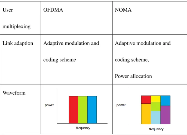
The advantage of NOMA is that it increases the spectral efficiency by superposing
multiple signals on power domain. However, the drawback of NOMA is that NOMA
should be used with SIC receiver to make it promising, and it will increase the
receiver complexity and processing delay [7]. The comparison of the differences
between OMA and NOMA is shown in table 2.1 below:
User
multiplexing
OFDMA NOMA
Link adaption Adaptive modulation and
coding scheme
Adaptive modulation and
coding scheme,
Power allocation
Waveform
Table 2.1 Comparison for OMA and NOMA
6
2.2 System model
In this study, the system includes a base station, two user equipments (UE), a
single-input single-output (SISO) forward channel, and an error-free feedback channel
between base station and UE. The UE keeps measuring the received signal-to-noise
ratio (SNR) and signal-to-interference-plus-noise ratio (SINR), and then it will report
the information back to base station with a constant feedback delay. It is assume that
the transmission power is constant, and the system is equipped with the proportional
fair scheduler, the adaptive modulation and coding scheme (AMC) mechanism and
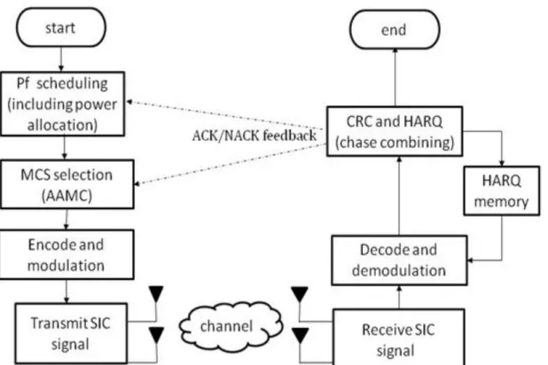
the HARQ mechanism. Fig. 2.2 is the simplified block diagram of the system
considered in this study.
Figure 2.2 System model for NOMA with AMC and HARQ mechanism
First, we assume that there are several UEs in the serving range of one beam, and
we decide the 2-UE transmission user pair from these users by a proportional fair
scheduler. During the process of scheduling, we use full search method to find the
most appropriate user pair and the power allocation for this user pair. Then we can
also decide the MCS for both users by the power allocation and the reported channel
information. In order to improve system throughput, the value of MCS threshold can
be adaptively adjusted by the adaptive threshold adjustment modulation and coding
scheme (AAMC) algorithm. After encoding and modulation, base station can
superposed the signal of both UEs and send the data packet to the SIC receiver of
each UE.
If UE receives and decodes the packet successfully, it will send an
acknowledgement (ACK) back to the base station. Otherwise, if UE failed to decode
the packet correctly, it will send a negative acknowledgement (NACK) back to the
base station and store the packet in memory. The stored packet can combine with
packets retransmitted by HARQ to get higher SNR or SINR for decoding. Both the
proportional fair scheduler and the AAMC algorithm will be affected by the
ACK/NACK signals feedback from the UE.
The basics of AMC and HARQ are introduced in Section 2.2.1and 2.2.2
respectively, the basic of proportional fair scheduler is introduced in Section 2.3.1,
8
and the exhaustive search proportional fair scheduler is introduced in Section 2.3.2.
2.2.1 Introduction to AMC Systems
In modern wireless communication, AMC systems have been widely adopted in
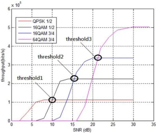
order to achieve a higher data rate or spectra efficient transmission. The concept of the
AMC mechanism is shown in Fig. 2.3.
Figure 2.3 Illustration of AMC mechanism
There are four MCSs used in the system, so there are three MCS thresholds. From
Fig. 2.3 we can know that if the transmitter switches to higher MCS when received
SNR higher than the threshold, the throughput can be improved. Even though bit error
rate (BER) might become higher when selecting the higher MCS, the system
throughput will increase and improve system performance. In practical system
implementation, the thresholds of AMC mechanism are determined by a
pre-determined lookup table for switching MCS.
2.2.2 Introduction to HARQ
Hybrid automatic repeat request (HARQ) is the joint use of automatic repeat
request (ARQ) and forward error coding (FEC) at the transmitter and receiver. Most
practical HARQ uses Cyclic Redundancy Check (CRC) code for error detection and
convolutional code or turbo codes for error correction [8].
There are 3 types of HARQ design, in this study, we will use the HARQ with
chase combining. HARQ with chase combining (HARQ-CC) is one kind of HARQ
design with soft combining, and it is better than the design which without soft
combining. When a data packet is declared in error after decoding, the receiver will
ask for its retransmission, and store the packet in the buffer instead of dropping the
packet. Despite that the packet is detected error, it still contains information, and it
will be a loss if discards the received packet. The stored packet will combine with the
retransmission packet to obtain a more reliable packet.
The example of HARQ-chase combining is shown in Fig. 2.4 below:
10
Figure 2.4 Example of chase combining [8]
In HARQ-CC, retransmissions consist of the same set of coded bits as the original
transmission, and the received SNR is increasing for each retransmission because of
obtaining diversity gain by receiving the same information in each retransmission.
After receiving retransmission packets, the receiver uses maximum-ratio combining to
combine each bit with the same bit from previous transmissions and fed to the decoder.
The combination with just the same codes is called chase combining. [9]
2.3 Proportional Fair Scheduling Algorithm
A base station can serve several users at the same time, and scheduler can assign
the resources among all users. If we use a maximum rate scheduler, the system will
only serve the user with good channel. In this study, we adopt proportional fair
scheduler as a scheduling method to achieve a good balance between system capacity
and user fairness.
However, scheduling in NOMA is more complex than in OMA. NOMA system
can serve multiple users in the same frequency band, so user pairing and power
allocation should be done by the scheduler. The basics of proportional fair scheduling
are briefly introduced in Section 2.3.1, and the scheduling method used in this study is
introduced in Section 2.3.2 respectively.
2.3.1 Introduction to Proportional Fair Scheduling
In NOMA system, the scheduler serves more than one user in each frequency band.
The user pairing significantly affects the system throughput and user fairness. Also,
the power allocation is important because it affects the
signal-to-interference-plus-noise ratio (SINR) of both users and their throughput. We
can calculate the proportional fairness metric (PF metric) and transmit the pair which
has the highest PF metric. Following is the simplified PF metric:
The term denotes the PF metric of the candidate user pair , which is the
summation of the PF metric of all users in the user pair . Term is the
instantaneous throughput of user with power ratio and MCS selection at time .
Term is the average throughput of user at time .
12
From the PF metric we can know that, if a user has transmitted more data, or a
user has lower instantaneous throughput, it will have lower priority. Thus, we can
achieve a good balance between system capacity and user fairness.
2.3.2 Exhaustive Search Proportional Fair Scheduling
User paring and power allocation are very significant but also problems in NOMA
scheduling. The power allocation for each user affects the user throughput
performance and the modulation and coding scheme (MCS) used for transmission of
each UE. There are lots of ways to decide the power allocation for the user pairs. In
order to achieve maximum rate, we can use full search power allocation to try all the
possible transmission power sets. However, full search power allocation is too
complicated and really hard to achieve.
In this study, we modified the scheduling method in [10], using exhaustive search
to try all user pairs. Even though the computation is higher, but can find the most
appropriate user pair. After deciding the user pair, we should also decide the
transmission power sets. Usually, users with lower channel gains are allocated more
transmission power than users with higher channel gains, and also with a constraint of
the total transmission power of 1. That is, the transmission power sets is ,
where is the transmission power for near user, is the transmission power for far
user, and , with the constraint that .
In order to reduce the complexity of optimal power allocation, we define 9
transmission power sets ((0.05, 0.95), (0.1, 0.9), (0.15, 0.85), (0.2, 0.8), (0.25, 0.75),
(0.3, 0.7), (0.35, 0.65), (0.4, 0.6), (0.45, 0.55)) for scheduling.
Following is the proportional fair scheduling algorithm:
Exhaustive search proportional fair scheduling algorithm
Step 1: Select a user pair and decide which user is near user and the
other is far user
We can compare the channel gain of each user to make the user with higher channel gain become near user , and another one become far user .
Step 2: Select a transmission power set
Select from the 9 transmission power sets defined above.
Step 3: Calculate the received SINR for both user by the reported CQI assuming
OMA and the transmission power set
As long as we have the information of power ratio and channel gain, which includes
AWGN channel and Rayleigh channel, then we can calculate received SINR by the
14
following sentences. Let total transmission power is channel gain of near user
is (dB), channel gain of near user is (dB), then we can get:
Where and is the received SNR of near user signal and far
user signal for near user, and is the received SNR of near
user signal and far user signal for far user.
In SIC system, near user will decode far user signal first and take near user signal as a
interference, far user will take near user signal as a interference as well. From (2.2) to
(2.5) and interference , we can calculate the received SINR of total received signal
for each user.
Where is the received SINR of total received signal for near user and
is the received SINR for far user.
Step 4: Calculate the multi-user PF metric
The term denotes the average throughput of the user . The term
denotes the instantaneous throughput of the user , where
denotes the candidate user set, equals to and denotes the expected
MCS by estimated SNR. The instantaneous throughput can be approximated by
comparing received SINR with predefined modulation and coding scheme (MCS)
threshold. The threshold of a MCS can be determined by transmitting signal with an
initial threshold and adjust the threshold to make BLER less than 1% under the MCS.
After calculating the PF metric of all users in the user pairs, we can get the multi-user
PF metric.
Step 5: Repeat Step 2-4 until all transmission power sets tried and we can get the
highest multi-user PF metric for the user pair
After Step 5, we can know the most appropriate transmission power set and MCS for
the user pair .
Step 6: Repeat Step 1-5 until all possible user pairs tried and we can get the
highest multi-user PF metric among all the user pairs and transmission power
sets
16
We choose the pair with the highest multi-user metric as the scheduled pair. If the
multi-user metric is the same among several pairs, we will choose the pair which has
the higher channel gain than other pairs on both near user and far user. If none of the
pairs is superior to other pairs on both user, then the earlier the pair is scheduled, the
higher priority it has.
After Step 6, we can get the scheduled pair with the most appropriate transmission
power set and MCS.
Step 7: From Step 6 we can get the near user and far user from the scheduled
pair which has the highest multi-user PF metric
Chap 3
New Design for HARQ in NOMA
Hybrid automatic repeat request (HARQ) plays an important role in
communication system nowadays, inaccurate channel information results in errors and
necessitates HARQ. HARQ can mitigate the errors caused by delayed and inaccurate
CQI feedback by retransmission. In OMA system, the importance of HARQ is
confirmed and the design method is well discussed. However, HARQ in NOMA
system is more complicated than in OMA and will encounter some problems such as
unsuccessful cancellation of interference and user pairing changed. User paring and
power allocation significantly affect the performance of HARQ in NOMA system [11].
In this study, we will discuss the difficulties in Section 3.1 and investigate a new
design for HARQ in NOMA to solve the problems in Section 3.2.
3.1 Difficulties of HARQ in NOMA
In OMA, after the base station transmits packets to UE, UE will send a positive
acknowledgment (ACK) or negative acknowledgment (NACK) back to base station.
The time between the base station transmitting the packet and receiving the ACK
18
signal is called ACK feedback delay. If the base station receives an ACK, it will know
the transmission successes. Otherwise, if the base station receives an NACK, it will
retransmit the same packet. HARQ in OMA has only one user in each frequency band,
so it is much simpler than in NOMA.
In NOMA, two scheduled users transmit simultaneously, the HARQ system
becomes complicated with power allocation and MCS choosing for near and far user.
Following is the example:
Figure 3.1 Decoding example for both users in NOMA system
Near user signal is transmitted by a lower power so far user can decode the packet
by regarding near user signal as interference. If the packet is declared in error, far user
can store the symbols in buffer and wait for soft combining. For near user, it must
decode far user signal first, so whether the near user can successfully decode the
packet or not is affected by not only the power and MCS of far user but also the
power and MCS itself.
If we arbitrarily pair the users or retransmit the packet, the performance of HARQ
will degrade seriously. There are several problems of HARQ need to be solved in
NOMA system, such as retransmission wasted, unsuccessful cancelation of
interference and user re-pairing.
3.1.1 Retransmission Wasted
In OMA, only one user can be scheduled in a subband. In NOMA, there are
multiple users can be scheduled in a subband. Even though one of the users received
wrong data, base station still needs to conduct retransmission. If base station
retransmits with the same user pair, it will be an unnecessary retransmission to the
user which has received the right data.
3.1.2 Unsuccessful Cancelation of Interference
Far user can decode the packet without doing interference cancellation, and near
user can subtract its component from received signal and decode it without the
interference of far user by successive interference cancelation. However, interference
may fail due to the inaccurate receiver channel information caused by CQI feedback
delay. We can store the superposed symbol in buffer because the symbol still contains
information.
20
3.1.3 User Re-pairing
In NOMA, base station serves multiple users in a subband and the user is pairing
by the scheduler and the status of the user could be changed. For instance, in the
initial transmission round, user A pairs with user B which has a worse channel than
user A. In this condition, user A is the near user in the pair. In the retransmission
round, user A may pair with user C by scheduler, where user C has a better channel
than user A. As long as the status of user A changed, some of the information saved in
the buffer in the initial transmission round becomes useless. If we use the wrong
information for chase combining, it will lead to performance degradation. The
condition of decoding symbols in initial round will affect that whether the information
stored in buffer is useful or not.
3.2 New design of HARQ
With the scheduling method introduced in section 2.3.2, we will investigate a new
HARQ design in this section. In this study, we use HARQ with chase combining, so
the MCS is the same in the initial transmission round and retransmission rounds. We
also use the technique of codeword-level SIC.
First, for the problem we mentioned in Section 3.2.1, we can solve the problem by
a simple method. Instead of retransmitting the succeeded user, we can schedule a new
user to lower the retransmission waste and improve the system performance.
To solve the problems of unsuccessful interference cancellation and user
re-pairing, we can adjust the information storing in the buffer and using for chase
combining.
For near user, it can store the symbol in buffer and waits for combining if it failed to
decode far user signal. The superposed symbols still contain information so it will be
a waste if not saving the useful symbols. In the retransmission round, if interference
cancelation successes, with codeword-level SIC, we can decode the far user signal
correctly and then encode the correct bits into symbols. The correct far symbols will
be stored in the buffer because they may be useful. If near user cancels the
interference successfully but fails to decode the signal of itself, it can memory both
the interference-free symbol and the correct symbol of far user in the buffer. With the
correct far symbols, we can ensure that interference cancelation will success if the
same packet is retransmitted. Also, with the interference-free symbol, near user can be
served as either a near user or a far user in retransmission round and mitigate the
degradation caused by user re-pairing. The HARQ in NOMA algorithm can be
summarized in Table 3 below:
22
UE Interference Cancelation Packet Decode Store in Buffer
Near Fail X Combined signal
Near Success Fail Far user signal
Near user signal
Near Success Success X
Far X Fail Combined signal
Far X Success X
Table 3.1 The information stored for HARQ chase combining
We can use the information of the symbol in buffer as good as possible to improve
system performance and mitigate the degradation caused by user re-pairing and
unsuccessful interference cancelation.
3.3 New Design of Proportional Fair Scheduling for HARQ in NOMA
From the simplified PF metric mentioned in chapter 2.3.1, we can notice that the
value of PF metric is significantly affected by average throughput of the user.
However, average throughput will increase only when the data packet is correctly
received. If the user failed to decode the data packet successfully, even though the
user still gets some information from the data packet, the average throughput will not
increase due to incorrectly decoded.
Sometimes, the user failed to decode the data packet because it is in a poor
channel condition, such as cell edge users. Although the instantaneous throughput is
low for the user poor channel condition, in order to balance the system throughput and
fairness, the user can still have high scheduling priority with a low average throughput.
These cell edge users will degrade the system performance because they need to be
served several times to achieve enough SNR by combining the retransmitted data
packet. Instead of calculating the efficient throughput in [12], when a user is served
but decode the packet unsuccessfully, we can change the calculation of average
throughput to improve system throughput.
3.3.1 Method 1: Proportional Fair Scheduling with Expected Throughput
We can use the simplest method to modify the calculation of average throughput
for PF metric. In the initial transmission round, no matter whether the data packet is
decoded successfully or not, the information bits of the data packet will be counted
into the average throughput. If the user cannot decode the data packet correctly until
the last HARQ retransmission round, the information bits which counted in the initial
transmission round will be deducted.
24
The advantage of this method is avoiding the system to serve the user in poor
channel condition. More user with better channel condition can be served and enhance
the system throughput by reducing the retransmissions cause by cell edge users. The
base station can serve the cell edge users when their channels become better so that
the cell edge throughput is not decreased.
However, average throughput used for PF metric only changes at the first
transmission round, the difference of each retransmission round is not considered with
this method.
3.3.2 Method 2: Proportional Fair Scheduling with Expected Throughput by Capacity
Different from the method mentioned in Section 3.4.1, we can measure average
throughput by SNR or SINR by channel capacity equation. By Shannon-Hartley
theorem, the channel capacity of an additive white Gaussian channel can be denoted
as
,
where is the channel capacity, is the bandwidth of the channel and is the
received SNR measured by base station. Thus, the PF metric becomes:
where is the equivalent rate calculate by (3.1).
UE reports the channel condition back to base station with a constant feedback delay
and base station will estimate how much information bits UE can receive in the
channel condition. If a data packet is combined with a retransmission packet by chase
combining, the received SNR of the packet can be regarded as the SNR summation of
both packets. Therefore, in the retransmission round, base station can measure the
amount of information bits by SNR summation in previous transmission. The
maximum of the expect throughput is equal to the information bits of the data packet.
In addition to the advantage of preventing the system from continuously serving
the cell edge users as the method mentioned in Section 3.4.1, this method can
distinguish the difference between each retransmission round. For a UE, more times a
packet is retransmitted means the UE is in a poor channel condition, so the lower
priority it will have.
3.3.3 Simulation Result of new PF Design
To compare the performance of the different PF scheduling algorithm, a
simulation was done on a NOMA with SIC based system. The simulation settings for
NOMA system are based on Table 3.2. The multiplexing technique used is NOMA,
the channel coding adopted here is turbo code (TC), and the HARQ type is chase
combining. The duration of a radio block is 1ms and the mobile speed is set to be
26
3km/hr. For the AMC system, three MCSs with nominal rates 1.0, 1.5, 2.0 are used for
far user in the system: MCS1 uses a code rate 1/2 TC with QPSK, MCS2 uses a code
rate 3/4 TC with QPSK, MCS3 uses a code rate 1/2 TC with 16QAM. For near user,
nine MCSs with nominal rates 1.0, 1.5, 2.0, 2.67, 3.0, 3.5, 4.0, 4.5, 5.0 are used in the
system: MCS1 uses a code rate 1/2 TC with QPSK, MCS2 uses a code rate 3/4 TC
with QPSK, MCS3 uses a code rate 1/2 TC with 16QAM, MCS4 uses a code rate 2/3
TC with 16QAM, MCS5 uses a code rate 3/4 TC with 16QAM, MCS6 uses a code
rate 7/8 TC with 16QAM, MCS7 uses a code rate 2/3 TC with 64QAM, MCS8 uses a
code rate 3/4 TC with 64QAM, MCS9 uses a code rate 5/6 TC with 64QAM. The
simulation result is shown in Fig. 3.2.
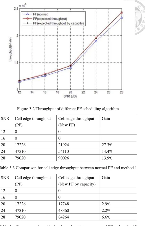
From the simulation result we can notice that both of the algorithms mentioned in
Section 3.4.1 and 3.4.2 have better performance than the original PF scheduling
algorithm on total system throughput. There is a slightly difference between the
performance method 1 and method 2. From Table 3.3 and Table 3.4, we can notice
that there is a large gain except in low SNR region which cell edge user is not
scheduled, and method 1 is better than method 2 on cell edge throughput.
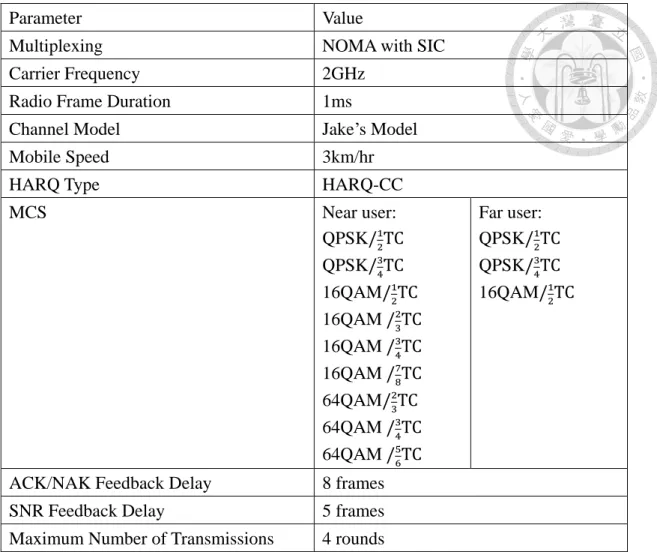
Parameter Value
Multiplexing NOMA with SIC
Carrier Frequency 2GHz
Radio Frame Duration 1ms
Channel Model Jake’s Model
Mobile Speed 3km/hr
HARQ Type HARQ-CC
MCS Near user:
QPSK QPSK 16QAM 16QAM 16QAM 16QAM 64QAM 64QAM 64QAM
Far user:
QPSK QPSK 16QAM
ACK/NAK Feedback Delay 8 frames
SNR Feedback Delay 5 frames
Maximum Number of Transmissions 4 rounds
Table 3.2 Parameters for simulation in NOMA system
28
Figure 3.2 Throughput of different PF scheduling algorithm SNR Cell edge throughput
(PF)
Cell edge throughput (New PF)
Gain
12 0 0
16 0 0
20 17226 21924 27.3%
24 47310 54110 14.4%
28 79020 90026 13.9%
Table 3.3 Comparison for cell edge throughput between normal PF and method 1 SNR Cell edge throughput
(PF)
Cell edge throughput (New PF by capacity)
Gain
12 0 0
16 0 0
20 17226 17748 2.9%
24 47310 48360 2.2%
28 79020 84264 6.6%
Table 3.4 Comparison for cell edge throughput between normal PF and method 2
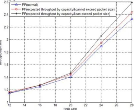
We also try the more aggressive method which makes method 2 without the constraint
of packet size. The simulation result is shown in Fig. 3.3. We can see that the system
throughput of method 2 without constraint is higher than which with constraint, but
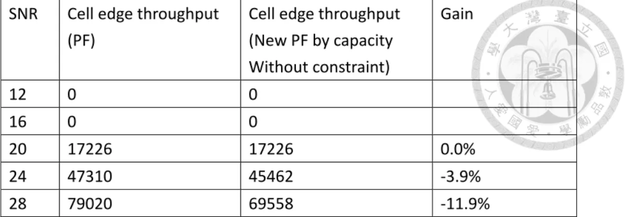
the cell edge throughput is lower. From Table 3.5, we can find that the cell edge
throughput of the new algorithm is even lower than the original PF scheduling
algorithm because the algorithm is serving less cell edge users to improve the
performance of system throughput.
Figure 3.3 Throughput of different PF scheduling algorithm
30 SNR Cell edge throughput
(PF)
Cell edge throughput (New PF by capacity Without constraint)
Gain
12 0 0
16 0 0
20 17226 17226 0.0%
24 47310 45462 -3.9%
28 79020 69558 -11.9%
Table 3.5 Comparison for cell edge throughput between normal PF and method 2 without constraint
3.4 The Comparison of Different Aggressiveness for Far User in HARQ
In this section, we discuss how the aggressiveness affects system throughput. As
we mentioned in Section 2.2.2, HARQ mitigates the errors caused by delayed and
inaccurate CQI feedback for both the near and the far UEs. With HARQ, the MCS can
be aggressively selected such that even though the error probability of the first
transmission of a packet may be high, the overall throughput can be improved. In this
case, it may be necessary to allow the UEs to be aggressive such as selecting higher
MCS according to the channel statistics. By allowing higher order MCS for the far
UE to make it aggressive, the system throughput can be improved.
The simulation parameters are mostly same as the settings of Table 3.2 except the
MCS used for far user, and the simulation result is shown in the Fig. 3.3. The blue line
is the throughput of using three MCSs for far user in the system: MCS1 uses a code
rate 1/2 TC with QPSK, MCS2 uses a code rate 3/4 TC with QPSK, MCS3 uses a
code rate 1/2 TC with 16QAM, and the red dotted line is using the MCSs above for
far user excluding MCS3.
Thus, from the simulation result, it is shown that allowing the far UE to use higher
order MCS than QPSK can achieved better system throughput.
Figure 3.4 Comparison for far user using different MCS
32
Chapter 4
Adaptive Threshold Adjustment Algorithm for HARQ in NOMA System
For practical systems, the AMC mechanism is always designed for the worst-case
channel conditions and lead to inefficient utilization of the full channel capacity [13].
So, we need an adaptive threshold adjustment algorithm for AMC systems [14]. In
this chapter, we will introduce the adaptive threshold adjustment algorithm on NOMA
system in Section 4.1 and Section 4.2, and show the simulation result in Section 4.3.
4.1 Adaptive Threshold Adjustment Algorithm
When the transmission starts, there is a data frame of information bits with
length generated from the information source block and buffered to be transmitted.
The information bits are processed by channel coding and punctured some bits to
match specific code rate afterward. After puncturing, the coded bits are modulated and
the symbols are used for transmission. Assume that information bits is encoded by
coding rate , and modulated with modulation rate , the nominal rate can be
defined as
To maximize system throughput, the transmitter must select the MCS which fit the
channel condition best. That is, the transmitter has to select an MCS such that
,
where is the instantaneous received SNR value measured and reported by the
receiver, is the MCS index and is a function of , and is the system throughput. It
is assumed that there is a set of possible MCSs, denoted as
, and MCS table contains a set of thresholds, denoted as
. The MCS selection strategy can be expressed as
From the discussion above, the purpose of the algorithm is to select an MCS which
fits current channel condition best and can adjust the MCS threshold adaptively to
maximize the system throughput. For HARQ with chase combining, the same coded
frame is transmitted at each retransmission round [9]. According to the MCS selection
policy in transmission rounds, there are two types of HARQ scheme. The first type is
called non-adaptive HARQ, and the second type is called adaptive HARQ [adapt
HARQ]. Non-adaptive HARQ means that the MCS used in retransmission round is
34
the same as the MCS used in initial transmission round. On the contrary, adaptive
HARQ means the MCS used in initial transmission round and retransmission round
can be different. For HARQ with chase combining, the MCS is decided in the initial
round, so the HARQ protocol adopted in the system in this study is non-adaptive
HARQ. The algorithm can be separated into two parts, initial transmission round and
retransmission rounds.
Initial Transmission Round
To analyze the problem, we define the event that the transmitter gets an ACK
signal when is selected. Assuming that the ACK/NACK feedback is error free,
the average throughput when with nominal rate is selected in the initial
transmission round with effective SNR is
,
where the number of times is selected in the initial transmission round, is
the number of times occurs, and is the probability the event occurs and can
be defined as
Since the optimal thresholds cannot be known before the data communication take
place, the transmitter only initializes a look up table with a pre-determined set of
thresholds . As the concept shown in Fig 2.3, the condition for the threshold to
be optimal and maximizing the throughput is that the MCS on either side of it yields
the same threshold which satisfies
.
As the method similar in [15], we define a threshold as
,
where and define the lower and upper ranges of the threshold band respectively.
To analyze the throughput around the threshold band, we define the notations
that means the probability of the event , means the event that the is
selected when the effective SNR falls in the threshold band , and means the
event that the ACK signal is received when is used in the threshold band .
If and is small enough, (4.6) can be approximated by
To simplified (4.8), we force the following assumption for each threshold band:
,
which can be achieved by alternating the MCS selection when the measured SNR
falls in a threshold band as:
36
If happens, select the next time .
If happens, select the next time .
Otherwise, when , the MCS is kept the same as the
previous transmission.
From (4.8) and (4.9), we have:
Note that when the measured SNR does not fall in any threshold band, the MCS
selection is regular, i.e., selecting when the measured SNR is
between and . Considering the problem how to adaptively adjust the thresholds,
we may adjust the threshold to be higher by when happens. This is because,
with (4.9), the formulation in (4.8) with more frequent means lower throughput
of than at . Thus, the current value is lower than its optimal value.
Similarly, we may adjust the threshold to be lower by when happens. The
MCS threshold adjustment algorithm in initial transmission round is summarized as
follows:
If happens, then update with .
If happens, then update with .
When is at its optimal value, the up-adjustment and down-adjustment should
balance up, so does not move on average. Therefore, we need
Comparing (4.10) and (4.11), the relationship for step-size values can be derived as
Retransmission Rounds
In HARQ retransmission rounds, the nominal rate and the information bits to be
transmitted were already fixed in the initial transmission round so the transmitter does
not need to decide which MCS should be used. Even if the retransmissions of a frame
use same MCS as the initial transmission, we can still adjust the threshold by the
ACK/NACK feedback information. We define the threshold band same as (4.7),
and is used in the j-th transmission round. Note that when the measured SNR
does not fall in any threshold band, the MCS selection is regular, and the adaptive
threshold value adjustment algorithm in retransmission round is:
If happens, then update with ,
If happens, then update with ,
where means the event that the is select when the measured SNR falls in
threshold band in j-th retransmission round, and are the step-size values for up
and down adjustments respectively, and the relationship between is the same as
(4.12).
38
4.2 Adaptive Threshold Adjustment Algorithm in NOMA System
For near user, it can subtract interference-free signal after SIC. For far user, it is
regarding the near user signal as interference and the interference is affected by power
allocation. Thus, regardless of the influence caused by power allocation, we can take
NOMA system as two independent systems and adaptively adjust the MCS thresholds
for each user. The system throughput is improved by the algorithm and the simulation
results are presented in Section 4.3.
4.3 Simulation Results
To verify the performance of the proposed algorithm, a simulation was done on an
NOMA based system with the setting in Table 4.1. The initial thresholds are {8.7dB,
14.2dB, 15.9dB, 16.9dB, 20.2dB, 21.1dB, 22.1dB, 23.1dB} for near user and {7.7dB,
13.3dB} for far user. For the first case, the step-size is 0.1dB and band size is 0.2dB;
for the second case, the step-size is 0.12dB and band size is 0.25dB
Parameter Value
Multiplexing NOMA with SIC
Carrier Frequency 2GHz
Radio Frame Duration 1ms
Channel Model Jake’s Model
Mobile Speed 3km/hr
HARQ Type HARQ-CC
MCS Near user:
QPSK QPSK 16QAM 16QAM 16QAM 16QAM 64QAM 64QAM 64QAM
Far user:
QPSK QPSK 16QAM
Initial Thresholds 8.7dB,14.2dB,
15.9dB,16.9dB, 20.2dB,21.1dB, 22.1dB,23.1dB
7.7dB,13.3dB
ACK/NAK Feedback Delay 8 frames
SNR Feedback Delay 5 frames
Maximum Number of Transmissions 4 rounds
Threshold Band Size 0.2dB/0.25dB
Threshold Adjustment Step-size 0.1dB/0.12dB
Table 4.1 Parameters for AAMC algorithm in NOMA system
The simulation results are shown in Fig. 4.1 and Fig. 4.2. From Fig. 4.1 and Fig.
4.2, it can be seen that the proposed method results in better throughput than the
traditional fixed threshold method due to the ability of tracking thresholds over each
transmission.
40
Figure 4.1 Comparison for fixed MCS threshold and AAMC
Figure 4.2 Comparison for fixed MCS threshold and AAMC
In the process of adjusting threshold, the thresholds varies rapidly may lead to
performance degradation. From Fig. 4.3, we used the adjusted threshold by AAMC
algorithm with the step-size is 0.1dB and band size is 0.2dB for fixed threshold and
the performance is remarkably improved.
Figure 4.3 Throughput of using adjusted threshold for fixed threshold
42
Chapter 5
Conclusions and Future Works
In this thesis, we applied the HARQ and AMC to the NOMA system with SIC
receiver. We investigated a scheduling method and new method of measuring average
throughput for PF scheduling. With the scheduling method, we can use the
information stored in buffer effectively to improve the efficiency of HARQ. The new
PF algorithm can prevent from continuously serving cell edge users and provide more
accurate measurement for average throughput. The new PF algorithm can achieve a
notable gain for either system throughput or cell edge throughput and have better
performance.
In addition, we discussed the influence of aggressiveness for MUST with HARQ.
By allowing higher order MCS for the far UE to make it aggressive, the system
throughput can be improved.
Also, we proposed an algorithm which can adaptively adjust MCS thresholds in
NOMA system. The systems usually affected by fading channel seriously and thus
systems are always designed for the worst-case channel conditions. With the adaptive
threshold adjustment algorithm, the MCS thresholds can adapt to the current channel
condition and get better system throughput. Simulation results show that the algorithm
worked successfully and achieved significant performance gain by adjusting the MCS
thresholds to better value on NOMA system.
Some directions of future works are discussed. In the work of this study, we
assume that the feedback channel between base station and UEs is ideal. Also, we
ignore the correlation between near user and far user to simplify the NOMA system
for AAMC algorithm. We might take these issues into consideration to make this task
more complete.
44
BIBLIOGRAPHY
[1] C.-X. Wang et al., “Cellular architecture and key technologies for 5G wireless communication networks,” IEEE Commun. Mag., vol. 52, no. 2, pp. 122–130, Feb.
2014
[2] Y. Saito , A. Benjebbour , Y. Kishiyama and T. Nakamura, “System level
performance evaluation of downlink non-orthogonal multiple access (NOMA) ” IEEE
VTC, June 2013
[3] Evolved Universal Terrestrial Radio Access (E-UTRA); LTE Physical
Layer-General Description (Release 8). 3GPP TSG RAN TS 36.201 Version 8.3.0,
September 2009.
[4] S. Kallel and D. Haccoun, “Generalized type II hybrid ARQ scheme using
punctured convolutional coding” IEEE Transactions on Communications, vol.38, no.
11, pp. 1938-1946, November 1990.
[5] A. Das, F. Kuan, A. Sampath, and H.-J. Su, “Adaptive asynchronous incremental
redundancy (A2IR) with fixed transmission time interval (TTI) for hsdpa,” in Proc.
2002 IEEE 13th International Symposium on Personal, Indoor and Mobile Radio
Communications (PIMRC 2002), Lisboa, Portugal, September 15-18 2002, pp.
1083-1087.
[6] A. Li, A. Benjebbour, X. Chen, H. Jiang, and H. Kayama, “Investigation on
hybrid automatic repeat request (HARQ) design for NOMA with SU-MIMO,” in Proc.
IEEE 26th Annu. Int. Symp. Pers., Indoor, Mobile Radio Commun. (PIMRC),
Aug./Sep. 2015, pp. 590–594.
[7] Y. Saito, Y. Kishiyama, A. Benjebbour, T. Nakamura, A. Li, and K. Higuchi,
“Non-orthogonal multiple access (NOMA) for future radio access,” in Proc. IEEE
VTC2013-Spring, pp. 1-5, Dresden, Germany, June 2013
[8] . Dahlman, S. Parkvall, J. Skold, and P. Beming, 3G Evolution: HSPA and LTE
For Mobile Broadband , 2nd edition. Elsevier, 2008.
[9] S. Kallel and D. Haccoun. Generalized type II hybrid ARQ scheme using
punctured convolutional coding. IEEE Trans. Commun., 38(11):1938-1946,
November 1990.
[10] 3GPP, R1-155931,NTT DOCOMO, “System-level evaluation results for downlink multiuser superposition schemes,” Malmö, Sweden, Oct. 5 – 9 2015
[11] Li, Anxin, et al. "Investigation on hybrid automatic repeat request (HARQ)
design for NOMA with SU-MIMO." Personal, Indoor, and Mobile Radio
Communications (PIMRC), 2015 IEEE 26th Annual International Symposium on.
IEEE, 2015.
[12] Zheng, Haitao, and Harish Viswanathan. "HARQ aware scheduler in downlink
46
packet data systems." Vehicular Technology Conference, 2003. VTC 2003-Fall. 2003
IEEE 58th. Vol. 3. IEEE, 2003.
[13] A. J. Goldsmith and S. G. Chua, “Adaptive coded modulation for fading channels,” IEEE Transactions on Communications, vol. 45, pp. 595-602, May 1998.
[14] Liao, Wei-Shun, and Hsuan-Jung Su. "Throughput maximization by adaptive
threshold adjustment for AMC systems." APSIPA ASC (2011).
[15] Su, Hsuan-Jung, and Li-Wei Fang. "A simple adaptive throughput
maximization algorithm for adaptive modulation and coding systems with hybrid
ARQ." Proc. International Symposium on Communications, Control, and Signal
Processing (ISCCSP), Marrakech, Morocco. 2006.
[16] Schaepperle, Joerg, and Andreas Rüegg. "Enhancement of throughput and
fairness in 4G wireless access systems by non‐orthogonal signaling." Bell Labs
Technical Journal 13.4 (2009): 59-77.
[17] Nagisa, O. T. A. O., Yoshihisa Kishiyama, and Kenichi Higuchi. "Performance
of non-orthogonal multiple access with SIC in cellular downlink using proportional
fair-based resource allocation." IEICE Transactions on Communications 98.2 (2015):
344-351.
[18] Su, Hsuan-Jung. "On adaptive threshold adjustment with error rate constraints
for adaptive modulation and coding systems with hybrid ARQ." 2005 5th
International Conference on Information Communications & Signal Processing.
IEEE, 2005.
[19] Chen, Fan, et al. "Research on threshold adjustment algorithm in adaptive
modulation and coding." 2006 IEEE 17th International Symposium on Personal,
Indoor and Mobile Radio Communications. IEEE, 2006.
[20] Tarchi, Daniele, et al. "Novel link adaptation for TETRA cellular systems."
International Journal of Communication Systems 22.4 (2009): 483-501.
[21] 3GPP, R1-157352, NTT DOCOMO, “System-level evaluation results for downlink multiuser superposition schemes,” Anaheim, USA, Nov. 5 – 9 2015
[22] 3GPP, R1- 168072, National Taiwan University, “Design issues of MUST with HARQ,” Gothenburg, Sweden, Aug. 22 – 26 2016
[23] 3GPP, R1- 168071, National Taiwan University, “Performance of MUST with
HARQ,” Gothenburg, Sweden, Aug. 22 – 26 2016
[24] Akyildiz, Ian F., David M. Gutierrez-Estevez, and Elias Chavarria Reyes. "The
evolution to 4G cellular systems: LTE-Advanced." Physical Communication 3.4
(2010): 217-244.
[25] Lan, Yang, et al. "Considerations on downlink non-orthogonal multiple access
(NOMA) combined with closed-loop SU-MIMO." Signal Processing and
Communication Systems (ICSPCS), 2014 8th International Conference on. IEEE,
48 2014.
[26] Li, A., A. Harada, and H. Kayama. "Investigation on low complexity power
assignment method and performance gain of non-orthogonal multiple access
systems." IEICE trans. commun (2014).
[27] Das, Arnab, et al. "Performance of hybrid ARQ for high speed downlink packet
access in UMTS." Vehicular Technology Conference, 2001. VTC 2001 Fall. IEEE
VTS 54th. Vol. 4. IEEE, 2001.
[28] Oviedo, Jose Armando, and Hamid R. Sadjadpour. "A New NOMA Approach for
Fair Power Allocation." arXiv preprint arXiv:1605.00390 (2016).
![Figure 2.1 Basic NOMA applying SIC receiver in downlink [7]](https://thumb-ap.123doks.com/thumbv2/9libinfo/9600287.628800/12.892.167.749.775.977/figure-basic-noma-applying-sic-receiver-downlink.webp)
![Figure 2.4 Example of chase combining [8]](https://thumb-ap.123doks.com/thumbv2/9libinfo/9600287.628800/18.892.144.775.112.451/figure-example-of-chase-combining.webp)