Feedback Decoupling and Distortion Correction Based Reactive Compensation Control for Single-phase Inverter
Jin-Wu Gong, Bai-Feng Chen, Pei Li, Fei Liu, Xiao-Ming Zha, Member, IEEE
School of Electrical Engineering Wuhan University Donghu South Road, No. 8
Wuhan, China
[email protected], [email protected] Abstract -- This paper analyzes the characteristic of single-
phase converter system and establishes the active power and reactive power model in d-q axis, which is the same with the there-phase system in d-q axis and could employ decoupling feedback control for reactive compensation and active power control. For realizing d-q transformation in single-phase system, a new orthogonal decomposition method with sliding window filter (SWF) is presented. While, for the sake of SWF, the coupling between active power and reactive power could not be eliminated completely, which leads to poor dynamic process in control system and significant distortion in compensation current. For overcoming these shortages, this paper presents a distortion correction based control strategy, which not only could improve the control system dynamic characteristics, but also eliminate compensation current’s distortion. At last, simulations with different control strategies demonstrate the validity and superiority of proposed control strategy.
Index Terms--single-phase inverter; reactive compensation;
distortion correction; sliding-window filter.
I. INTRODUCTION
Single-phase grid-connected voltage-source converter is widely used in power distribution system and other power equipments, such as hybrid cars, Distributed Generation (DG) and rectifier [1]-[3]. In some condition, single-phase converter serves as compensator, such as active power filter (APF), Distribution Static Synchronous Compensator (D- STATCOM). Single-phase converter serves as an interface between system and loads, and provides efficient and reliable AC source or DC source. All this applications require a high performance controller for converter system. Advanced controllers should not only have superior transient response, but also provides zero steady-state error as well as low output current or voltage THD (total harmonic distortion).
Much has been done for the model and control of single- phase converter in the past years; some literature present success applications in special condition [4]-[5], however, some restrictions let some controllers have poor performance.
On example is d-q transformation for three-phase converters could get active and reactive components instantaneously, which make it easier to analyze and design controllers in DQ rotating frame because all time-varying state variables of the converter become DC time-invariant. While in single-phase converter, active and reactive components couldn’t be got instantaneously though d-q transformation, which at least
needs two independent phases.
This paper presents distortion correction based reactive compensation strategy for single-phase converter in d-q axis.
The d-q transformation loop, which has a relative small delay, is realized through orthogonal decomposition. The organization of this paper is as follows: Part II analyzes the characteristic of single-phase power circuit and adopts decoupling feedback control for active and reactive power control in d-q axis; Part III presents the single-phase d-q transformation, which is realized through orthogonal decomposition; Part IV analyzes the control system and puts forward distortion correction based reactive compensation control strategy, which not only could improve the control system dynamic characteristics, but also eliminate compensation current’s distortion; Part V presents different simulation results, which demonstrate the superiority of proposed control system.
II. SINGLE-PHASE D-QMODEL AND DECOUPLING CONTROL A. Single Power Model in d-q Axis
In three-phase power system, the active power and reactive power could be got through a d-q transformation, which also enables a decoupling feedback control for active and reactive currents. The feedback control adopts a PI controller for both active and reactive current control loops, and reduces the control system to a first-order transfer function. The PI gains could be arbitrarily designed to meet the required response [6]. For power control of single-phase converter, it is necessary to establish the active power and reactive power model in d-q axis.
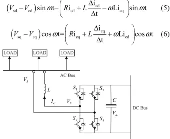
Fig.1 shows the system configuration of single-phase inverter system, V is system voltage of connection s point,V is output voltage of converter, c i is output current, c they are represented in (1),(2),(3) respectively, LandRare total ac inductance and resistance of interface inductor coupling the inverter to system, and the relationship between system voltage and output voltage of converter is shown in (4):
( ) sd sq
sin t+ sin t+ cos t
S S
V =V ω ϕ =V ω V ω (1)
( )
csin t+ cdsin t+ cqcos t
VC =V ω θ =V ω V ω (2) PEDS2009
( )
c c cd cq
i =i sin ω φt+ =i sin t+i cos tω ω (3)
c c
i i
S C t
V −V =LΔ +R
Δ (4) Through (1) to (4), the relationship between active power and reactive power could be deduced in (5) to (6). (5) and (6) indicate the single-phase system has coupling between active power and reactive power, and the power model is the same with there-phase system. So a decoupling feedback control could be also used for the reactive and active control. The power model of single-phase system is presented in Fig.4.
(Vsd−Vcd)sin t=ω ⎛⎜⎝Ricd+LΔΔicdt −ωLicq⎞⎟⎠sin tω (5)
(Vsq−Vcq)cos t=ω ⎛⎜⎝Ricq+LΔΔicqt +ωLicd⎞⎟⎠cos tω (6)
S1
S2
S3
S4
VS
L
Ic VC C
Vdc
Fig. 1. Configuration of single-phase converter system
ωL
R sL +
1
cd +
V Vsd
Vsq
Vcq
icd
icq
−
R sL +
1
−
ωL
+
Fig. 2. Power model in d-q axis
B. Decoupling Feedback Control for Single-phase Inverter Couple between active power and reactive power could be decoupled through a decoupling feedforward control, which needs to know the source voltage and exact parameters of the total resistance and inductance of interface inductor. While, it is often impossible to precisely know parameters.
Uncertainties in parameters would deteriorate the dynamic response and steady-state errors of control. A complete decouple could be achieved through decoupling feedback control, which uses PI controller for both active and reactive current control loops. In three-phase converter system, the controlled system is reduced to a first-order transfer function,
which let control system could have fast response [6]. The decoupling feedback control system diagram for single-phase inverter is presented in Fig.3.
I P
K K +s
ωL ωL + −
+
+
+
−
−−
−
P I
K K
+ s Vcd∗
Vcq∗
icd∗
icq∗
icd
icq
Vsq
Vsd
Vcd
Vcq
+
cq cq)
V =V∗
cd cd
V =V∗
Fig. 3. Decoupling feedback control system
III. SINGLE-PHASE D-Q TRANSFORMATION
For control system realization, signal detection is an important loop; the performance of detection loop would decide the all control system performance. In three-phase inverter system, with information of three-phases, the active and reactive components could be got instantaneously through d-q transformation, which has no time delay theoretically. While, due to only one phase’s information exists in single-phase inverter system, the active and reactive could not be got instantaneously, although some literatures introduce imaginary orthogonal circuits to realize d-q transformation. One method to create imaginary orthogonal circuit is to shift real circuit state variables by 90 degree [7].
this method introduces a delay of a quarter of a cycle, which means the controller can not respond to any changes in the system immediately and would impact the performance of the converter. Another method to construct orthogonal imaginary circuit is by differentiating the state variables of the real circuit [5]. This method could construct imaginary circuit theoretically, but differential is unreliable and hard to realize in digital controller.
VS sinωt cos tω
I
−+ id
iq f
I Ih id
iq C−1
Fig. 4. Block diagram of single-phase d-q transformation
0
1 n
i i
n∑= x
1, ...2 n
x x x
xin xout
Fig. 5. Block diagram of sliding-window filter
PEDS2009
In this paper, d-q transformation of single-phase current is realized through orthogonal decomposition and sliding- window filter (SWF). The block diagram of SWF is presented in Fig.5. With orthogonal decomposition, the active and reactive components could be got as a single-phase d-q transformation. Compared with the three phase system d-q transformation, SWF would bring a delay in orthogonal decomposition to get DC components [8]-[9].
The proposed orthogonal decomposition is presented in Fig.4. The phase angle ( tω ) is detected through a phase- locked loop (PLL), which provides sin tω and cos tω . Multiplying with sin tω and cos tω respectively, current is decomposed into AC signals and DC signals, which contains the active component and reactive component. Through the SWF, the AC signals could be eliminated and DC signals are remained. The Arithmetic process of orthogonal decomposition is shown in (7) and (8):
( )
c cd cq cd
i sin ω φt+ ⋅2sin t iω = +i sin 2 t-i cos 2 tω ω (7)
( )
c cq cd cq
i sin ω φt+ ⋅2cos t iω = +i sin 2 t+i cos 2 tω ω (8) Traditional SWF would add the signals of a cycle (0.02s), while, (7) and (8) mean the SWF could let the width of sliding-widow be 0.01s. Suppose the A/D sample speed is 100 KHz, and the sampler could sample 2000 points in a cycle. The transfer function of traditional sliding-window filter is
2000
1 1
( ) 1 1
( ) ( ) 2000 1
y n z
H z x n z
−
−
= = ⋅ −
−
( ) ( 1) ( 2) ( 1999)
2000
x n +x n− +x n− ⋅⋅⋅ +x n−
= (9)
The transfer function of proposed sliding-window filter is given by
1000
2 1
( ) 1 1
( ) ( ) 1000 1
y n z
H z x n z
−
−
= = ⋅ −
−
( ) ( 1) ( 2) ( 999)
1000
x n +x n− +x n− ⋅⋅⋅+x n−
= (10)
The bode plots of above two sliding-window filter is present in the Fig.6 and Fig.7, which show traditional SWF have good filtering effect for more harmonic signals. While, proposed SWF would have smaller time delay in low- frequency band when they are just used for 2nd harmonic.
Fig. 6. Block diagram of traditional SWF
Fig. 7. Block diagram of proposed SWF
I P
K K + s
ωL ωL
R sL+
1
R sL+
1
ωL ωL + −
+
+ +
+ +
−
−
−−
−
P I
K K
+ s Vcd∗
Vcq∗
Vsd
Vsq
icd∗
icq∗
icd
icd
icq
icq
Vsq
Vsd
+
Vcd
Vcq
+
−
−
cq cq)
V =V∗
cd cd
V =V ∗
Vdc∗ +
V−dc
VS sinωt cos tω
Ic icd
icq
Fig. 8. Block diagram of feedback decoupling based control system
PEDS2009
IV. PROPOSED CONTROL STRATEGY
A. Analysis and Simulation of Decoupling Feedback Control
The proposed control strategy is presented in Fig.8, which attains the active and reactive current components in d-q axis through orthogonal decomposition, and controls the inverter to inject desired current into electric system through decoupling feedback control
In three-phase inverter system, the control system of i and cd icq is reduced to a first-order transfer function. While in single-phase inverter system, the SWF would bring time delay and make coupling between active power and reactive power couldn’t be eliminated completely. The simplified block diagram of control system is shown in Fig.9.
In Fig.5 and (10), the transfer function of SWF is
2 5 10
10
1
1000 (1 )
s
SWP s
G e
e
−
−
−
−
= −
⋅ −
i
i (11) Suppose the PI controller is same for both the active current and reactive current, the two current control loops have similar transfer function. The open-loop transfer function of active current is given by
2 2
1 (1 )
PI SWP LR o Icd
LR SWP
G G G
G− = G G
+ − (12)
And the all transfer function of i is cd
*
2 2
1 (1 )
PI SWP LR
cd cd
LR SWP PI SWP LR
G G G
I I
G G G G G
= ⋅
+ − +
2
*
2 2
(1 )
(1 ) (1 (1 ) )
PI SWP SWP LR
cq
PI SWP LR SWP LR
G G G G
G G G G G I
+ − ⋅
+ ⋅ + − (13)
The open-loop transfer function of reactive current is
2 2
1 (1 )
PI SWP LR o Icq
LR SWP
G G G
G− = G G
+ − (14)
And the all transfer function of i is cq
*
2 2
1 (1 )
PI SWP LR
cq cq
LR SWP PI SWP LR
G G G
I I
G G G G G
= ⋅
+ − +
2
*
2 2
(1 )
(1 ) (1 (1 ) )
PI SWP SWP LR
cd
PI SWP LR SWP LR
G G G G
G G G G G I
− − ⋅
+ ⋅ + − (15)
Equations (11), (13) and (15) present that: (1) SWF brings time delay for control system; (2) the coupling between active control loop and reactive control loop couldn’t be decoupled completely. Equations (12) and (14) could be used to design the controller. However the transfer function of SWF is nonlinear, which brings difficulties for controller design. Although certain nonlinear control theory could provide some methods for PI controller design, this paper establishes a model on MATLAB/simulink for control parameters design. The model would be detailed in part V.
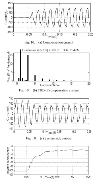
the simulation results is presents in the Fig.10.
Fig. 10. (a) Compensation current
Fig. 10. (b) THD of compensation current
Fig. 10. (c) System side current
Fig. 10. (d) Reactive component at system side +
icq∗
−
I P
K K +s
+ −
R sL+
1
+
I P
K K +s +
− sL+R
1 icd
icq
icd∗
GSWF GPI
1−GSWF
GLR
Fig. 9. Simplified block diagram of control system
PEDS2009
B. Distortion Correction Based Control Strategy
The simulation results in Fig.10 presents the decoupling feedback control has a poor dynamic response, which is brought by SWF. The first reason for poor dynamic response is that SWF brings time delay and make the dynamic process has oscillations, which is presented in Fig.10 (d); the second reason is that SWF is nonlinear and cause the output voltage and current of inverter to have distortion, which let the output current have harmonics. Fig.10 (a) and Fig.10 (b) show that the output current has a THD of 15.42% and has significant low-order harmonics.
In order to overcome these shortages, this paper presents a distortion correction based control strategy, which is based on the theory of active power filter (APF) [10]. In other words, A distortion correction loop to could be designed to eliminate harmonic current to make the inverter only output fundamental current. If the output harmonic current could be eliminated completely, the control system could just deal with fundamental signals, the oscillation caused by harmonics would also be reduced. Besides, compared with APF system, distortion correction controller aims to regulate the modulation signal (Vc∗) and make no harmonic current flow into system.
The realization of distortion correction system is through a feedback control of output harmonic current. The output harmonic current (I ) could be detected through orthogonal ch decomposition, which is already presented in Fig.4.
Orthogonal decomposition could the harmonic componentI . ch And the controller for I is just Proportional control. The ch distortion correction based reactive compensation strategy for single-phase converter is presented in Fig.11. The input signals of control system are load side current, inverter output current, voltage of connection, DC voltage of inverter.
TABLE I. SYSTEM PARAMETERS
System side value Converter value
system voltage 220V L 0.2mH
f 50Hz R 0.01Ω
ILq 103A
Vdc 600V
V. COMPUTER SIMULATION
To verify the proposed control strategy, a simulation of reactive compensation system with single-phase inverter is carried out on MATLAB/simulink. The single-phase inverter system configuration is shown in the Fig.12; the system parameters are presented in Table. I.
The load side has 103A reactive current. Without distortion correction loop, the simulation results are already presented in Fig.10, and the controller parameters are
P 0.05
K = ,KI = . The response time of controller is about 2 0.1s and the dynamic process has oscillation. Besides, the THD of output current is about 15.42%.
The simulation results of distortion correction based control strategy are shown in Fig.13; the Proportional coefficient for distortion correction loop are 2, the controller
I P
K K + s
ωL
ωL + −
+
+ +
−
−−
−
I P
K K + s
Vcd∗
Vcq∗
icd∗
icq∗
icd
icq
Vsq
Vsd
+ Vdc∗ +
V−dc
VS sinωt cos tω
Ic
icq
icd icd
icq C−1
−+ icf
ich Vch∗
Vcf∗
+ +
+ + c
V∗ Vc
c c )
V =V∗
Fig. 11. Block diagram of proposed control system
S1
S2
S3
S4
VS
L
Ic VC C
Vdc
L Lp Lq
I =I +I
S Sp Sq
I =I +I
Fig. 12. Single-phase reactive compensation system
PEDS2009
parameters are KP = ,1 KI = . The response time of 5 controller is about 0.04s. Besides, the THD of output current is only about 1.44%. So distortion correction control loop not only reduce the THD of compensation current but also improve the control system dynamic characteristics, which is reflected in the faster response time and bigger PI parameters.
VI. CONCLUSION
This paper establishes the active power and reactive power model for single-phase inverter in d-q axis and adopts decoupling feedback control for reactive compensation. The realization of single-phase d-q transformation is through orthogonal decomposition and a new SWF, which has time- delay and non-linear characteristics. In order to overcome these shortages, a distortion correction based control strategy is presented in this paper. Proposed distortion correction loop not only improves the control system dynamic characteristics,
but also eliminates the current distortion. Simulations under different control strategies demonstrate the validity and superiority of proposed control strategy. Proposed control strategy could also be adopted for single-phase PWM rectifier, APF; cascaded multilevel inverter based D- STATCOM etc.
REFERENCES
[1] B. Singh, B. N. Singh, A. Chandra, K. Al-Haddad, A. Pandey, and D.
P. Kothari. “A review of single-phase improved power quality ac-dc converters.” IEEE Transactions on Industrial Electronics, 50(5): pp.
962–981, October 2003.
[2] K. P. Louganski, and J. S. Lai, “Reactive Power Control Realization in Single-Phase Active Front End Converters,” in Proceedings of IEEE APEC, Anaheim. USA, pp. 797-803, Feb 2007.
[3] Y. Xue, L. Chang, S.B. Kjaer, J. Bordonau and T. Shimizu,
"Topologies of single-phase inverters for small distributed power generators: an overview" IEEE Transactions on Power Electronics, Vol. 19, Issue 5, Page(s):1305 – 1314, Sept. 2004.
[4] M. J. Ryan, W. E. Brumsickle, R. D. Lorenz, "Control topology options for single-phase UPS inverters", IEEE Transactions on Industry Applications, Vol. 33, Issue 2,Page(s):493-501, March-April 1997.
[5] R. Arman, B. Rolando, and A. C. Baisden, “A d-q frame controller for a full-bridge single-phase inverter used in small distributed power generation systems,” in Proceedings of IEEE APEC, Anaheim. USA, pp. 641-647, February 2007.
[6] F. Z. Peng and J. S. Lai, “Dynamic Performance and Control of a Static Var Generator Using Cascade Multilevel Inverters,” IEEE Transactions on Industry Applications, Vol. 33, No.3, pp. 748 -755, May/June 1997.
[7] R. Zhang, M. Cardinal, P. Szczesny, M. Dame, “A grid simulator with control of single-phase power converters in D-Q rotating frame”, in Proceedings of IEEE 33th PESC, Vol. 3, 23-27. pp. 1431- 1436, Jun.
2002.
[8] U. A. Miranda, L. G. B. Rolim, and M. Aredes, “A DQ synchronous reference frame current control for single-phase converters,” in Proceedings of IEEE 36th PESC, pp. 1377–1381, Jun. 2005.
[9] J. Salaet, S. Alepuz, A. Gilabert, and J. Bordonau, “Comparison between two methods of DQ transformation for single-phase converters control. Application to a 3-level boost rectifier,” in Proceedings of IEEE 35th PESC, vol. 1, pp. 214–220, Jun. 2004.
[10] K. Smedley, L. Zhou, and C. Qiao, “Unified constant-frequency integration control of single-phase active power filter,” IEEE Transactions on Power Electronics, vol. 16, pp. 428-36, May 2001.
Fig. 13. (a) Compensation current
Fig. 13. (b) THD of compensation current
Fig. 13. (c) System side current
Fig. 13. (d) Reactive component at system side
PEDS2009