Transverse Flux Machines
with Distributed Windings for In-Wheel Applications
Salwa Baserrah * , Keno Rixen, Bernd Orlik *
*Institute for Electrical Drives, Power Electronics and Devices University of Bremen
Bremen, Germany
Abstract — Transverse flux machine (TFM) useful for in-wheel motor applications is presented. This transverse flux permanent magnet motor is designed to achieve high torque-to-weight ratio and is suitable for direct-drive wheel applications. As in conventional TFM, the phases are located under each other, which will increase the axial length of the machine. The idea of this design is to reduce the axial length of TFM, by placing the windings around the stator and by shifting those from each other by electrically 120 o or 90 o , for three- or two-phase machine, respectively. Therefore, a remarkable reduction on the total axial length of the machine will be achieved while keeping the torque density high. This TFM is compared to another similar TFM, in which the three phases have been divided into two halves and placed opposite each other to ensure the mechanical balance and stability of the stator. The corresponding mechanical phase shifts between the phases have accordingly been taken into account.
The motors are modelled in finite-element method (FEM) program, Flux3D, and designed to meet the specifications of an optimisation scheme, subject to certain constraints, such as construction dimensions, electric and magnetic loading. Based on this comparison study, many recommendations have been suggested to achieve optimum results.
Keywords- Transverse flux; in-wheel motor; distributed windings; flux-concentrated; surface permanent magnet
I. INTRODUCTION
Direct-driven motors are the new trend of the electric motors, which are considered to improve the efficiency of the electric vehicle (EV) drive system. This type of motors is directly mounted inside the wheel, called also in-wheel or hub motor. Such motor will eliminate transmission gears or mechanical differentials with their associated energy loss; and this is the main reason behind the improvement in efficiency.
Various comparison surveys of merits and demerits have been already reported the types of electric motors that are suitable for EV. Induction motor drives are preferred for EV propulsion purpose in [1]. Alternatively, permanent magnet brushless dc motor featured compactness, low weight and high efficiency. DC, induction, permanent magnet synchronous, switched reluctance and brushless DC are compared in [2] and it is concluded that among these motors, PM and brushless DC motors are attractive choice for EV applications.
Different compact constructions of different electric motors, such as synchronous, PM and switched reluctance motors, of relatively high torque density and achieving improvements on the overall efficiency of the electric vehicle are constructed in [3-5] and still there are more electric motor design optimisation schemes appearing in electric vehicle research.
In comparison with conventional radial-flux machines, axial-flux permanent magnet (AFPM) machines will allow exploitation of a higher percentage of stator winding for torque production [6-7]. Several AFPM wheel motors designed for electric cars are compared in [8] and multi-stage AFPM constructed in [9], and concluded that machines of interior PM give the best compromise in terms of power density, efficiency, compactness and long-term overload capability characteristics. Permanent magnet (PM) motor for solar-powered in-wheel motor is demonstrated and examined in [10], where an axial field air gap winding is utilized.
TFM with flux concentrated configuration is designed for in-wheel applications and reported in [11]; however, only one phase has been constructed and tested. The idea of TFM with two-phase windings located around the stator for small power range is patented in [12] with axial permanent magnet (PM), however, no thorough study or design improving investigations have been carried out. Nevertheless, a comparison study of power density for axial flux machines with various topologies have been conducted in [13], where general purpose sizing and power density equations are being presented. A sector-wise, three phase surface PM-TFM with distributed windings as an inner rotor machine is described and analytically modelled in [14]. Although the power factor is stated to be improved to 0.7; the torque density is reduced.
Following the suggestions of previous experiences, a novel design methodology on permanent magnet transverse flux for in-wheel motor applications will be presented, where compact design of small axial length and maximum exploitation of radial space with high torque density is the design target.
II. STRUCTURE OF NEW DESIGN
Transverse flux machine underlines the high torque
motors, which can be classified as surface permanent magnet
1.a. 1.b.
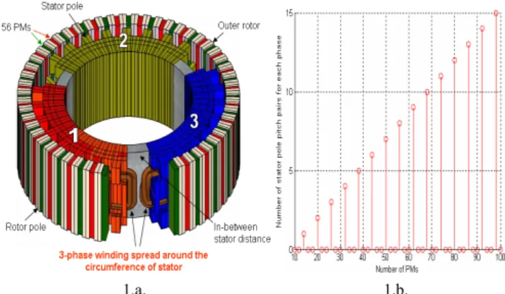
Figure 1. Three-phase FC-TFM with full distributed windings 1.a. Machine structure 1.b. PMs number selection TFM (SPM-TFM) and flux concentrated TFM (FC-TFM).
Permanent magnets in SPM-TFM are magnetised in direction perpendicular to the direction of rotation, whereas the permanent magnets in FC-TFM are of parallel magnetisation direction to the rotation. Since the torque density achieved by FC-TFM is higher than the SPM-TFM, it is preferred to use FC topology for constructing in-wheel motors, though it is mechanically difficult in construction. In this description, flux concentrated configurations will be considered in details, other constructions for SPM-TFM will be pointed out too.
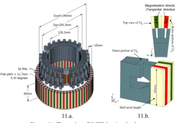
In order to locate the windings around the stator, certain steps should be managed so that the mechanical shift of the windings with respect to the rotor will coop with the phase of the electric loading. Specifying the number of poles in the stator for each phase is the starting step and it should be selected as an even number, on each layer of the stator, so that the winding can be wounded feasibly around them. Fig. 1.a shows the 3-phase FC-TFM of 56 poles with distributed three full phases. The pole number represents the number of the PMs or the rotor poles. The pole pitch, τ p is defined in millimetres as the air gap diameter times 3.141 divided by the pole number or simply 360 o divided by the number of poles, which is equal to 6.43 o , expressed in mechanical degrees. The PMs are marked with different colours indicating opposite tangential magnetisation direction. Each stator phase has sixteen pole pitches, 16τ p . Each two complete stator poles correspond to 2τ p . The stator poles are divided into two parts, one is located in the centre of the stator axial length, and the other part consists of stator poles that are shifted by 1 τ p and are divided and placed in top and bottom layers so that each side of the winding will be sandwiched by the stator poles.
As the pole pitch pair number for each phase is specified for this machine to be 8, the corresponding number of rotor poles for each phase is sixteen, since each 1 τ p is equivalent to the mean distance between two rotor poles. By placing the first phase of the stator and its corresponding rotor phase span;
the first step of the design will be accomplished. In the same way, the second stator phase which is identical to the first phase but displaced by a mechanical shift that corresponds to 120 o electrically is added. The mechanical shift, θ 3 φ , is equivalent to 2/3 τ p and calculated by (1).
o 3
θ 120 × 2
φ = P (1)
where P = number of poles
In order to achieve sufficient areas between the phases around the stator, a quantity of multiple of τ p will be added to
θ 3 φ . Therefore; the mechanical displacement between the stator phases for full winding arrangement, δ 3 - φ F , can be calculated as in (2).
3 - 3 p
δ φ F = θ + φ q × (2) τ
where q = 0, 2, 4, 6, ..., P
The machine is designed for q = 2, consequently, the number of rotor poles for the two phases can be easily deducted as 16 poles (i.e. phase 1) + 2 poles (i.e. 2τ p ) + mechanical shift + 16 (i.e. phase 2), this will result in 34 rotor poles and a fraction that corresponds to 2/3 τ p . Following the same manner, the third phase of the stator will be placed, which will lag phase one by 4/3 τ p i.e., 240 electrical degrees.
The resulting number of rotor poles for the whole machine will result in: 3×16 poles (i.e. 3 phases) + 3×2 (i.e. 2τ p ) + 2 poles (i.e. 3× θ 3 φ = 3× (2/3 τ p )) = 56 rotor poles. As a matter of fact each stator phase corresponds to 120 mechanical degrees i.e., 1×16 (i.e. phase1) + 1(i.e. 2τ p ) +1(i.e. θ 3 φ = 2/3 τ p ). Thus, 18τ p + 2/3 × τ p = (56/3) × τ p = (56/3) × 6.43 o = 120 o .
The mechanical phase span, Θ 3 -F φ , can be calculated by (3).
3 - 3 -
360 -3 δ
3
o F
F φ
φ
Θ = × (3)
By setting q = 1 and considering only one-half of the mechanical shift in (2), the inner distances between the phases can be reduced and it is calculated to be 1×τ p + 0.5× θ 3 φ . This will require reversing the winding terminals. As reducing the distance between the phases will be superior to the interaction torque, the effect of interaction mutual flux between the phases will rise and considering the phases to behave independently, will not be to a certain aspect correct.
TFM with distributed windings around the circumference can be constructed only with a certain number of poles in the rotor in order to confirm the mechanical shift with the balance of the construction. The great advance in power electronic devices technology and control schemes allow us to design efficient power supplies with different phase shifts e.g., of 30 o or 60 o , thus makes the construction of TFM with distributed windings with mechanical shift other than 120 o possible. Fig.
1.b shows the allowable number of poles suitable for building
TFM with distributed windings around the circumference in
relation to number of stator pole number on each layer for
each phase. This figure has been conducting with considering
the mechanical distances between phases for q = 2.
3.a. 3.b.
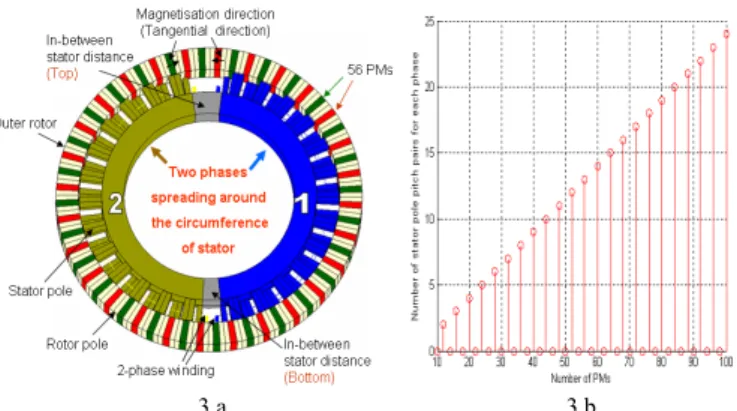
Figure 3. Two-phase FC-TFM with full distributed windings 3.a. Machine structure 3.b. PMs number selection
2.a. 2.b.
Figure 2. Three-phase FC-TFM with split distributed windings 2.a. Machine structure 2.b. PMs number selection
In order to consider the mechanical balance of the machine, each stator phase has been divided into two parts and placed opposite each other so that when one part of phase is feeding the machine, its facing part will also be on operation, therefore, this will emphasise the axial mechanical stress balance symmetrically. This scheme for locating split phases around the stator is shown in Fig. 2.a for TFM with 56 poles.
The same method that was carried out with full winding distribution, through placing the windings around the stator, is applied here with taking into consideration a distance of 4/3 τ p
between the split phases, i.e., half the distance of distributed full winding structure as shown in (4).
3 -S 3 p
1 2
δ = θ + τ
q q
φ φ
⎛ ⎞ ⎛ ⎞
× ×
⎜ ⎟ ⎜ ⎟
⎝ ⎠ ⎝ ⎠ (4)
where q = 2, 4, 6, ..., P
The mechanical shift is considered to be half that of the full three-phase windings, i.e., 1/3 τ p . In this way, the phases can be supplied with reverse currents. Therefore, the phase sequence will be as each phase lags the other by 120 o for full distributed winding machine, while reverse order of phases will be expected for the split phase TFM. This can definitely be explained in terms of the mechanical shift, since 1τ p + 1/3 τ p corresponds to electrically 240 o and similarly 2τ p + 2/3 τ p
corresponds to electrically 120 o i.e., the phase shift is of 120 electrical degrees. The suitable pole number for split phase three-phase FC-TFM is shown in Fig. 2.b where each phase is divided into two equal parts.
The actual mechanical phase span for each phase part can be calculated by (5).
3 - 3 -
360 -3 δ 3
o S S
q q
φ φ
Θ = × (5)
The same rotor is used for two different stator structures with full distributed and split distributed windings. The most difficult part to be constructed is the rotor since the permanent magnets are difficult to be fixed around the frame. However, the construction of stator is simplified by making use of SMC material, which permits flexible machine design and features additionally, very low eddy current loss and possibilities to improve thermal characteristics. Despite the low permeability of the SMC material, it is considered to be most appropriate
for PM-machines as the magnetic reluctance of the magnet dominates the magnetic circuit; hence, the motor will be insensitive to the permeability of the core [15].
III. OTHER POSSIBLE ALTERNATIVE STRUCTURES Two-phase TFM can as well be constructed with distributed full and split windings around the stator. Fig. 3.a shows two-phase TFMs with full windings of 56 poles viewed as a top section. Apparently, the two-phase TFM with full windings distribution will exhibit additional noise problems since there is mechanical instability, due to unequal mechanical distance between the two phases for any choice of P. The mechanical shift for 2-phase winding is 50% τ p and can be calculated by (6).
o 2
θ 90 × 2
φ = P (6)
The unequal mechanical distances between the phases can be calculated by using (7) and (8).
2 -F
12 p
δ φ = θ + φ q × (7) τ
2 -F
2p 2
δ φ = τ θ q × − (8) φ
where q = 0, 1, 2,..., P
The mechanical phase span, Θ 2 -F φ , can be obtained from (9).
( 2 -F
12 -F
2)
2 -
360 - δ +δ 2
o F
φ φ
Θ φ = (9)
In Fig. 3.b, the possible number of stator pole pitch pairs for each phase has been calculated for different pole numbers.
By comparing Fig. 1.b and Fig. 3.b, the suitable rotor pole number for 3-phase and 2-phase windings configuration, respectively, are not the same. Obviously, the pole number arrangement, which has been applied for 2-phase machine can not be applied for the 3-phase machine and vice versa.
Dividing the two phases into parts will eliminate the
mechanical instability and insure equal distances between all
Figure 6. Three-phase FC-TFM with full distributed windings 5.a. 5.b.
Figure 5. Three-phase SPM-TFM with full and split distributed windings 5.a. Full winding 5.b. Split winding
Figure 7. Three-phase FC-TFM with split distributed windings the phases’ divisions. The split 2-phase distributed windings
construction is shown as top view of 58 poles in Fig. 4.a, where each phase is divided into two parts. The suitable number of PMs for this construction is shown in Fig. 4.b
The distances between the phases have been chosen to allow feasible spaces between the windings as found by (10).
2 -S 2 p
δ = θ + φ φ q × (10) τ
where q = 0, 1, 2,..., P
The phase span for each part of 2-phase machine can be found out by applying (11). This equation assumes that each phase of the two phases has been divided into two parts.
2 - 2 -
360 - 4 δ 4
o S
S φ
φ
Θ = × (11)
SPM-TFM can as well be constructed with distributed windings. Fig. 5 shows 3-phase SPM-TFM with full and split distributed windings. The end-windings will add a significant effect to the leakage inductance of SPM-TFM.
Note that the red and green parts on the rotor represent the PMs, of opposite magnetisation direction, which are placed next to each other in a circle. The magnetisation direction of the PMs in SPM-TFM is in axial direction, while in FC-TFM is in tangential direction. Rotating magnets can be modelled with a complex current sheet and using the convective- diffusion equation for the translation motion, through which a fast steady-state model is obtained [16].
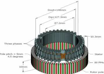
IV. CONSTRUCTION OF SMALL FC-TFM A. Test Operation
In order to insure the operation of the machine, two small FC-TFM machines have been simulated with number of poles of 80. The best selection of the number of poles will be stated through running several finite element (FE) simulations and examining the torque density productivity through calculating the torque constant [13].
In order to achieve strong magnetic fields for small machine volume and weight, rare earth permanent magnets are used (e.g. NdFeB) in the designs. Fig. 6 and Fig. 7 show two
different FC-TFMs with full and split distributed windings, respectively.
B. FEM Investigation
The two motors undergo 3D magnetostatic simulations.
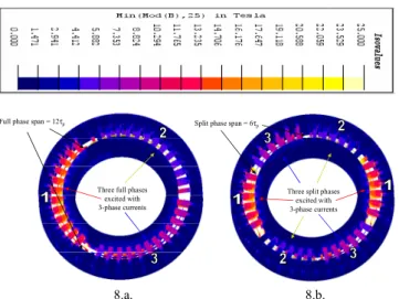
Flux density distributions are displayed in Fig. 8 for both the machines, while the rotor at a mechanical position of 50% of τ p . The phases are excited with 3-phase currents in each motor.
4.a. 4.b.
Figure 4. Two-phase FC-TFM with split distributed windings
4.a. Machine structure 4.b. PMs number selection
Average Torque
9.a. 9.b.
Figure 9. Torque components of 3-phase FC-TFM with full and split distributed windings
9.a. Full winding 9.b. Split winding
10.b.
Figure 10. FE- simulation of three phases individually including in- between distances of FC-TFM with full distributed 3-phase windings 10.a. Output torques obtained directly from Flux3D simulations 10.b. Output torques derived after mathematical manipulations
10.a.
Three full phases excited with 3-phase currents
Full phase span = 12τp Split phase span = 6τp
Three split phases excited with 3-phase currents
8.a. 8.b.
Figure 8. FE-simulation of three-Phase FC-TFM with full and split distributed windings
8.a. Full winding 8.b. Split winding
The split phase construction operated with the same electric loading that is applied to full winding machine. Fig.8.a shows flux density for full winding variant and Fig.8.b for split winding case. The flux density of the stator poles in one phase will be of a higher value than those of the other two phases since the peak value of the magnetic field of the current for this phase that supports the magnetic field of the PMs presents at the mechanical position of 0.5τ p .
Cogging torque due to attraction forces between active PMs and iron parts in the stator, reluctance torque, due to saliency facing the air gap, interaction torque due to interaction between the magnetic fields of PMs and armature current are the torque components of the TFM, which are shown in Fig.9. Fig. 9.a shows the average torque for full winding structure is almost the same as its corresponding value for split phase structure (22.75 Nm), which is demonstrated in Fig. 9.b. This is obviously the result, because the same electric loading of full winding case is applied in split winding case study.
Other simulations have been carried out for only 2 τ p for each phase with Flux3D Software from Cedrat [17]. Since the software will calculate the torque for only 2τ p and then it will apply a factor of periodicity, it is possible then to divide the
output torque from simulation by number of pole pairs to get a resultant torque for only 2 τ p . Fig.10.a. plots the torque components over 1τ p of one phase for complete 80 poles as the machine has no distances between the phases. Since each phase in full winding structure covers 24τ p , therefore, the torque produced from simulating a periodical TFM of 2τ p will be scaled by a factor of 12/40 to get the torque for each phase.
This process is repeated for each phase, taking into account the mechanical phase shift between the phases. The simulations of in-between distances have also been taken into account and plotted in Fig.10.a; however, it should be scaled.
Adding the torques for the three phases including the torques due to distances between the phases after scaling gives average torque of ≈23.5 Nm, which appears to be similar to that generated for the whole machine simulation as shown in Fig. 9. It is worth to be mentioned here that the distances between the phases have no big influence on the generated output torque, which can be clearly deduced from Fig.10.b.
The effect of these distances on the torque is only addition of
40mm
Half axial length Stator portion of 2τp
Rotor portion of 2τp
Top view of 2τp
Magnetisation direction (Tangential direction)