國立臺灣大學電機資訊學院電子工程學研究所 碩士論文
Graduate Institute of Electronics Engineering College of Electrical Engineering and Computer Science
National Taiwan University Master Thesis
適用於溫度感知三維晶片內網路之傳輸層協助路由演 算法和架構
Transport-layer Assisted Routing Algorithm and Architectures for Thermal-Aware 3D NoC
銀子駒 Yin Tzu-Chu
指導教授:吳安宇博士 Advisor: AN-YEU WU, Ph.D.
中華民國一百年六月
June, 2011
誌謝
兩年的研究生活終告結束,此時我即將步出校門,走完最後一段校園路程。
回想這段時光,滿是歡笑與汗水,以及成長的喜悅。從進入 Access 實驗室到今
日的點點滴滴,都是我這一路上最珍貴的回憶。
感謝我的指導教授吳安宇老師,您教導我身為一個研究生的自覺,開啟我 對研究題目的興趣,也在研究過程中不斷給予建議與激勵,讓我瞭解做研究的 態度與方法。感謝我的口試委員:呂學坤老師、李進福老師和李建模老師,謝 謝您們能蒞臨指導以及給予我建議和修正方向。
感謝實驗室每一位學長同學學弟妹。謝謝 Foster 在我剛進入實驗室時帶領
我。謝謝小昊在我論文陷入瓶頸時給予指導。林彥、thinking、yagaru、阿 ben、詹公、坤志跟恩瑞,你們總能在我報告陷入盲點時適時的糾正以及親切指 導。謝謝賢楷、郁豪、紹維、朝陽,你們陪我一起撐過各個艱苦時光,以及一 起享樂。謝謝輝舜、明翰、姿伶、冠宇、怡萱和寬育,能當你們學長是我的榮 幸。謝謝玉霜等助理幫忙了許多事務。我永遠記得這兩年中,大家一起打牌、
打電動、唱歌、看電影的時光。我永遠懷念大家一起出遊、聚餐、打球的歡樂。
謝謝你們的陪伴,以及教導我的一切。希望你們都能順利畢業,都能有個璀璨 的未來。
最後,謝謝爸爸,雖然你無法看到我順利完成碩士學歷,但你能參加到我 的碩士畢業典禮,對我是莫大的安慰跟鼓勵。爸媽和弟弟,謝謝你們給予我最 溫暖的親情和信任,有你們的陪伴是我人生中最大的福氣。祝媽媽跟弟弟能身 體健康,快樂生活以及萬事如意。
謹以這篇論文,獻給每位家人朋友。
銀子駒 謹誌 於台大電子所Access IC 實驗室 中華民國一百年七月二十五日
中文摘要
本文針對熱感知三維晶片內網路設計的效能降低問題做出演算法和架構設 計。傳統上為了確保溫度上安全以及避免效能被溫度限制大幅縮減,我們需要 及時溫度控制機制。若我們因為及時溫度控制機制,而針對快超過臨界溫度的 路由器來啟動壓制以便降溫,卻會造成系統拓撲變成非穩態不規則狀網狀拓撲。
為了在非穩態不規則狀網狀拓撲下讓封包能成功地傳送,我們為熱感知三維晶 片網路下,提出一個傳輸層協助路由演算法。根據實驗結果,我們提出的演算 法能有效地增加效能,以及使交通負擔量更加平衡。我們基於低成本實現技術,
提出記憶體降低技術,只需多 11.1%得實現成本,可獲得 1.7x 的吞吐量提升。
Abstract
In this thesis, we proposed algorithm and architecture design for performance reduction in thermal-aware 3D network-on-chip (NoC). To ensure thermal safety and avoid huge performance back-off from the temperature constraint, run time thermal management is required. However the regulation of temperature requires throttling of the near-overheated router, which makes the topology become Non-Stationary Irregular Mesh (NSI-mesh). To successfully deliver packet in NSI-mesh, we propose a Transport Layer Assisted Routing (TLAR) secheme for thermal-aware 3D NoC.
Based on the experimental results, the proposed routing scheme can significantly improve the performance and balance traffic load. For low cost implementation, we also propose memory reduction techniques, and we gain 1.7x throughput improvement for only 11.1% area overhead.
i
Contents
List of Figures ... iii
List of Tables ………vi
Chapter 1
Introduction ... 1
1.1 Motivation and Goal ... 1
1.1.1 3D IC and 3D Network-on-Chip ... 1
1.1.2 Thermal Issue for 3D Network-on-Chip ... 4
1.1.3 Goal and Contribution ... 6
1.2 Thesis Organization ... 8
Chapter 2
Related Works and Problem Description9
2.1 Run-Time Thermal Management for 3D NoC System ... 9
2.2 Definition of Non-Stationary Irregular Mesh 3D NoC ... 10
2.3 Related Works of Reactive Routing for Thermal-Aware 3D NoC 12 2.4 Problem of Data Delivery in Non-Stationary Irregular Mesh 3D NoC ... 13
2.5 Summary ... 20
Chapter 3
Transport-Layer Assisted Routing ... 21
3.1 Operation Flow of Transport-Layer ... 21
3.2 Proposed Framework of Transport Layer Assisted Routing ... 26
3.3 Proposed Algorithm: Downward-Lateral Deterministic Routing (DLDR) ... 28
3.4 Summary ... 29
Chapter 4
Performance Evaluation ... 30
4.1 Setting of Simulation Environmentst ... 30
4.2 Traffic balance and rate of transmitting packet under different routings ... 33
4.2.1 Network Sustainability and Degree of Graceful Degradation... ... 37
4.2.2 Run-Time Temperature and Throughput ... 38
4.3 Summary ... 42
ii
Chapter 5
Architecture Design for Transport-Layer
Assisted Routing ... 43
5.1 Traditional Architecture and Dataflow ... 43
5.2 Network Interface Design ... 45
5.2.1 Control Logic and FSM ... 45
5.2.2 Techniques of Memory Reduction ... 47
5.3 Dual-Mode Router Design ... 50
5.4 Implementation Results and Comparison ... 52
5.5 Summary ... 55
Chapter 6
Conclusion ... 56
References 57
iii
List of Figures
Fig. 1-1 On-chip communication trend [3]. ... 1
Fig. 1-2 Structure of Through Silicon Via (TSV)[14] ... 2
Fig. 1-3 (a) Topologies of 2-D and 3D NoC (b) Comparison of longest distance between 2D and 3D topologies (c) Comparison of path diversity between 2D and 3D topologies. ... 4
Fig. 1-4 Heat dissipation of 3D IC ... 5
Fig. 1-5 The growth of cooling cost. [20] ... 6
Fig. 1-6 Optimize performance under thermal limit ... 6
Fig. 2-1 Vertical throttling at different emergency level.[22] ... 10
Fig. 2-2 An example of Non-Stationary Irregular Mesh (NSI-Mesh) network. The topology changes in online operation because of the throttling in RTM ... 11
Fig. 2-3 Downward routing is applied to detour throttled routers [22] ... 12
Fig. 2-4 NoC composed by five layers ... 13
Fig. 2-5 Problem of usual reactive routing: (a) Source router is not serving (b) Destination router is not serving (c) Any router on selected path is not serving (d) Head of line Blocking ... 16
Fig. 2-6 (a) (iii) situation cannot guarantee routing path which router choose is routable. (b) Block other packet, which is same as (iv). ... 17
Fig. 2-7 Transport layer and network layer operation ... 19
Fig. 3-1 Network states and operation stages in transforming topology for run-time thermal management ... 22
Fig. 3-2 Block diagram of transport layer in the tile of thermal-aware 3D NoC. ... 23
iv
Fig. 3-3 Required time of transmitting throttling information ... 25
Fig. 3-4 Framework of proposed transport layer assisted routing scheme. The determination of lateral routable relies on the throttling information in transport layer. ... 26
Fig. 3-5 Path selection of proposed transport layer assisted routing scheme. ... 27
Fig. 3-6 (a) TLAR examples, and (b) checking dependency. ... 28
Fig. 4-1 Framework of co-simulation platform ... 31
Fig. 4-2 Construction of the model of a 4x4x4 3D NoC with simplified tile model from [30]. ... 31
Fig. 4-3 Throttling cases: (a) 1 router (b) 2 2*2*3 routers ... 32
Fig. 4-4 (a) Statistical traffic load distribution (STLD) of conventional design; (b) STLD of proposed TLAR framework with DLDR algorithm; (c) latency vs. network injection rate. ... 34
Fig. 4-5 (a) Statistical traffic load distribution (STLD) of conventional design; (b) STLD of proposed TLAR framework with DLDR algorithm; (c) latency vs. network injection rate. ... 35
Fig. 4-6 Average latency vs injection rate with (a) one router throttled and (b) two 2x2x3 pillars throttled. ... 36
Fig. 4-7 Different throttling cases ... 37
Fig. 4-8 Network sustainability of NSI-mesh 3D NoC, uniform traffic offered. ... 38
Fig. 4-9 Mutual-coupling co-simulation for throughput and temperature evaluation ... 39
Fig. 4-10 (a) Temperature and numbers of throttled routers of downward routing. (b) Throughput of downward routing. (c) Statistics of downward routing. ... 40
v
Fig. 4-11 (a) Temperature and numbers of throttled routers of TLAR (b) Throughput
of TLAR. (c) Statistics of TLAR. ... 41
Fig. 5-1 Architecture of network interface and router in the traditional 3D NoC ... 44
Fig. 5-2 Data flow between application layer, transport layer and network layer... 45
Fig. 5-3 Proposed architecture of TLAR ... 46
Fig. 5-7 (a) Reduce the size of topology table by storing the first non-throttled layer for each XY location. (b) Direct implementation. (c) Implementation with proposed TT reduction technique ... 48
Fig. 5-8 (a) The source destination pairs (s,d0), (s,d1), (s,d2), (s,d3) has the same source layer for lateral-first path, so their routing modes are identical. (b) For an X-Y-Z network, the size of RMM is XY bits. ... 49
Fig. 5-9 Our proposed 3D router architecture. ... 51
Fig. 5-10 Architecture of dual-mode routing computation ... 52
Fig. 5-11 Synthesis area (μm2) of TLAR NI. ... 54
vi
List of Tables
Table 4-1 Statistics of statistical traffic load distribution. ... 36
Table 5-1 Topology table comparison ... 48
Table 5-2 Routing mode memory comparison ... 50
Table 5-3 Design parameters ... 53
Table 5-4 Synthesis Area of NI and Router (μm2) ... 55
1
Chapter 1
Introduction
1.1 Motivation and Goal
1.1.1 3D IC and 3D Network-on-Chip
With the advances of the semiconductor technology, it is possible to integrate a large number of Intellectual Properties (IPs) on a single chip. However, the complexity of on-chip communication increases rapidly in the advanced VLSI technology, which impacts the performance and design complexity of SoC dramatically [1]-[4].
Fig. 1-1 shows the trend of the on-chip interconnections [3]. As the increases of IPs, the complexity of on-chip interconnections increases rapidly. Traditional methods, such as point-to-point interconnection and shared bus, are not enough to handle this problem. In order to provide more efficient interconnections and accommodate communication requirements, Network-on-Chip (NoC) has been proposed to as a novel and practical solution [5].
Fig. 1-1 On-chip communication trend [3].
2
Reduce system form factor by technology scale down in the planar IC becomes more difficult. Technology scaling has enabled an increase in integration density and a decrease in gate delay. However, higher integration densities require both a greater number of interconnects and longer interconnects. As the device delay reducing, performance is now dominated by the interconnect delay. In addition, power consumption and signal integrity have become more pronounced with technology scaling.
Three-dimensional (3D) integration is an effective design paradigm to manage the limitation of conventional two-dimensional IC [6]-[12]. 3D chip technology reduces interconnect delays by stacking multiple layer on top of each other, and by providing shorter vertical connections [13]. One of the most attractive technologies for 3D integration is based on Through Silicon Vias (TSVs), which cut across thinned silicon substrates to establish inter-die connectivity after die bonding [14], which is shown in Fig. 1-2. TSV based 3D IC has matured and motivated the combining of vertical interconnects with a NoC fabric, i.e., 3D NoC system.
Fig. 1-2 Structure of Through Silicon Via (TSV) [14].
3
Mesh-based NoC provides simple interconnection model for inter-IPs communication with the scalable and regular network architecture [2]. However, the intrinsic delay of IP and router cannot be reduced by network interconnection.
Besides, the wire length between routers is dominated by the area of IP. The long wires lead to a considerable propagation delay. To solve these problems, 3D NoC is capable to provide several features:
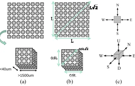
Higher IPs mapping density in the network: With vertical stacking, we can place more IPs in same area. The system form factor can be reduced.
As shown in Fig. 1-3(a), for 2D NoC we only have one plant placing IP.
However, we can stack more layers for 3D NOC, and the vertical distance is much smaller than horizontal distance, which we can ignore.
Lower connection cost and lower network power consumption:
The global net-length distribution scales in length as the square root of the number of strata [16]. For example as Fig. 1-3 (b), assume the number of strata is four, the net-length will be reduced by half. Besides, implementing the router hardware with 3D architecture can reduce the router area and inter-router wire length [17]. As the reduction of interconnection cost, the power consumption can also be reduced.
Higher network bandwidth: The router of 3D NoC provides vertical dimension comparing to 2 D router, as shown in Fig. 1-3 (c). This increases the routing path diversity of routing and prevents congestion of network, and increases the network bandwidth. Besides, the vertical interconnection
4
has a negligible propagation delay since the short distance of TSV. This feature can speed up the vertical data transmission of 3D NoC.
2D NoC
3D NoC
2D router
3D router
<40um
>1500um
Fig. 1-3 (a) Topologies of 2-D and 3D NoC (b) Comparison of longest distance between 2D and 3D topologies (c) Comparison of path diversity between 2D and 3D topologies.
1.1.2 Thermal Issue for 3D Network-on-Chip
Thermal issues are the main challenges of 3D-IC. 3D integration results in power density increasing linearly in the number of vertically-stacked active layers.
More-over, systems in the layers closer to the heat sink have higher cooling efficien- cies than those farther from the heat sink [18], which is shown in Fig. 1-4. For NoC- based 2D-IC, power consumption of routers will increase system temperature and make the thermal issues be a large and growing concern [18]. Therefore, the tempe- rature generated from NoC cannot be neglected. The networks consume a significant portion of the chip power budget [20][21], and hence having a substantial thermal impact. Therefore, understanding the joint thermal behavior of both processors and networks is the key to achieving efficient thermal design. There is an experimental
5
result from [19], by studying the thermal impact of the on-chip networks in the MIT Raw CMP [22].
Fig. 1-4 Heat dissipation of 3D IC.
For 3D NoC, thermal problem becomes more serious [23][24], as shown in Fig.
1-4. Because the 3D NoC heat dissipation path is longer than 2D NoC, it needs long cooling time to cool the tile. Since many dies stacking vertically in 3D IC, there are more systems and communication networks over same area. This will make the power density increase dramatically. Besides, 3D IC has heterogeneous thermal characteristics. Systems in the layers closer to the heat sink have higher cooling efficiencies than those farther from the heat sink [25].
The straightforward way to deal with thermal issue is using better heat sink.
However the cost of the heat sink grows exponentially with the power dissipation [20], as shown in Fig. 1-5. The more appropriate and cost effective method is using cheaper cooling device and applying thermal-aware design techniques [21]-[22].
6
Fig. 1-5 The growth of cooling cost. [20]
1.1.3 Goal and Contribution
In this thesis, we focus on Transient-State Temperature impact, which will trigger run time thermal management (RTM) to block input packets to router for cooling down temperature. However, because RTM will throttled routers and let them not service, the performance will degrade. We want to reduce the impact to optimize performance, and don’t let temperature increase above the thermal limit, as shown in Fig. 1-6.
Fig. 1-6 Optimize performance under thermal limit.
7
Base on above design issues, we have some features to achieve:
Provide algorithm to maximum throughput for NSI-mesh: Because the performance will degrade by using run-time thermal management (throttling), we should maximum performance under this constraint. 3D NoC suffers from thermal impact and we can’t increase thermal limit. We should provide algorithm to maximum performance under run-time thermal management.
Reduce area overhead: Because we will provide algorithm to maximum performance under RTM, the cost will increase due to proposed algorithm.
We should not increase cost too much, and maximum the performance effective.
Based on above design goal, we have to mitigate the performance degradation of thermal-aware designs for 3D NoC, and minimize the cost increase. A Transport Layer Assisted Routing (TLAR) scheme is proposed, and the architecture design is also proposed for estimating cost. Our contribution is listed as follow:
Transport-Later Assisted Routing Schemes for Vertical Throttling-
Based Thermal-Aware 3D NoC: Because of traffic congestion by
throttling, we propose Transport Later Assisted Routing Schemes to improve network performance. For this algorithm, we need transport-layer to solve the problem. Before transmitting packet to network layer, we should collect some simple information about network traffic situation and throttling information. After receive the information, we can arrange some routing paths to destination router, and choose the suitable paths to detour
8
throttled routers and make traffic load in network balance in order to make temperature more balance.
Architecture Design for Dual-Mode Router and Network Interference Because the laboratory focused on algorithm before, we need consider implement for the future research. So we can implement on three dimensional routers to consider cost and save area for future 3D router for simulation before three dimensional processes emerging.
1.2 Thesis Organization
The rest of this thesis is organized as follows: Chapter 2 introduces related works and introduces problems and solution of NSI-mesh. Chapter 3 presents proposed Transport-Layer Assisted Routing algorithm. Chapter 4 shows the experimental results of proposed techniques. Chapter 5 introduces proposed network interface and router architecture design, and compares area of synthesis results with proposed memory reduction techniques. Chapter 6, we conclude the work of this thesis and points out other potential future research direction.
9
Chapter 2
Related Works and Problem Description
The related and prior works about 3D thermal management and reactive routing for thermal-aware 3D NoC are introduced in this chapter. In order to utilize the interconnection advantage of 3D NoC, the related architecture designs are referred as our basic design. We evaluate the prior works of the thermal management and reactive routing to analyze the pros and cons of them. Finally, we discover problem and provide solution to solve these problem.
2.1 Run-Time Thermal Management for 3D NoC System
Since the thermal issue becomes more serious in 3D chips, Chao et al. proposed a thermal management for 3D NoC in [22], which is based on ThermalHerd [19]. The following techniques are proposed to control temperature:
Considering the heat flow in the 3D ICs, the author proposed a throttling scheme that shut down the routers along a vertical pillar, called the Vertical Throttling.
Because we want to cool efficiently, we should throttle a vertical path to let heat conduct to heat sink, which is like a cooling channel. When throttling the routers, system performance greatly degrades. To prevent the performance degradation, the Vertical Throttling determinates different throttling ratio based on the temperature of routers, as shown in Fig. 2-1. The experimental results show that the Vertical
10
Throttling provides an efficient way to cool the NoC, comparing to the conventional distributed throttling [19].
Fig. 2-1 Vertical throttling at different emergency level.[22]
2.2 Definition of Non-Stationary Irregular Mesh 3D NoC
Before describing the detail of problem of related work, we define a new term:
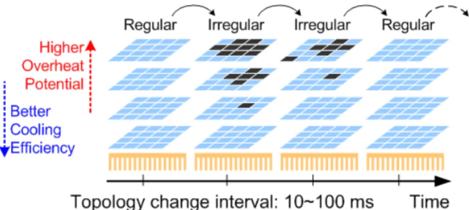
Non-stationary irregular mesh (NSI-mesh). First, irregular mesh means that there are routers or links removed in the network, which means the topology is not regular. We define the time-varying irregular-mesh topology as a Non-Stationary Irregular Mesh (NSI-mesh). A mesh-based thermal-aware 3D NoC adopting vertical throttling can be categorized in NSI-mesh topology. In NSI-mesh, the distributed thermal sensors detect temperature and trigger throttling. Throttling will cause topology changing during the online operation. The topology changing in thermal-aware 3D NoC results in the problem of packet delivery. For faster cooling, the traffic quota of the near- overheat router has to be very small and even zero. When the router reaches the limit of quota, it has to fully block the input packets. This behavior results in that the topology becomes a Non-Stationary Irregular Mesh (NSI-mesh), as shown in Fig. 2-2.
11
Although we do not know which router will throttled or not, but we know the present topology change by 107 cycles, and is different form fault tolerant NoC, which change topology by cycle.
Fig. 2-2 An example of Non-Stationary Irregular Mesh (NSI-Mesh) network. The topology changes in online operation because of the throttling in RTM.
The key characteristics of the NSI-mesh of Thermal-Aware Vertical Throttling (TAVT) based 3D NoC are: (i) if a router is throttled, all the routers above it are throttled, and (ii) if a router is not throttled, all the routers below it are not throttled.
As shown in Fig. 2-2. , the topology in offline stage and starting time of online stage is a traditional mesh. As temperature arises, near-overheat routers will be throttled, and the topology turns into irregular-mesh. Owing to the accuracy of temperature sensing, we can view that the network changes its topology at ms interval, which means 10 or 100 of millions cycles (107~108 cycles) if the NoC is operating at 1GHz.
12
2.3 Related Works of Reactive Routing for Thermal-Aware 3D NoC
To prevent the packet congested because of throttled tiles, we need reactive routing to detour throttled routers or prevent throttled paths. A downward routing algorithm [22] is proposed to migrate the horizontal routing to bottom layer. Besides, a traffic-aware downward level selection scheme is proposed to prevent network saturation. It compares the features of different downward levels. It also specifies the spatial thermal distribution in the 3D NoC system is non-uniform, while the traffic load is balanced. In order to balance the spatial thermal distribution, downward routing provides different downward levels for balancing thermal distribution, and the maximum network throughput improvement is shown under normal thermal limit.
The reactive routing is simply the extension of Downward Routing. While the Vertical Throttling guarantees the layer close to the heat sink always available, the reactive routing detours packets from throttled routers by different downward levels.
In the worse case, all the packets are transported at the layer close to the heat sink, as shown in Fig. 2-3.
Fig. 2-3 Downward routing is applied to detour throttled routers. [22]
13
2.4 Problem of Data Delivery in Non-Stationary Irregular Mesh 3D NoC
Downward routing can detour throttled routers successfully, and guarantee the routing path to destination router. However, if we use downward routing vertically to detour throttled router, all packet will congest around throttled router and the bottom layer, and the traffic become unbalance and performance will degrade soon. This is not algorithm we think as high performance based on throttling. We should consider reasons for packets being blocked in 3D NoC, and know how to solve them by our proposed algorithm.
Before describing reasons for fail delivery, we know NoC can be divided to five layers [33]: Application layer, Transport layer, Network layer, Data link layer and Physic layer, shown in Fig. 2-4
Fig. 2-4 NoC composed by five layers.
14
And we can define five layers as:
Application layer: Network architectures and control algorithms constitute the infrastructure and provide communication services to the end nodes, which are programmable in most cases.
Transport layer: Atop the network layer, the transport layer decomposes messages into packets at the source. It also resequences and reassembles the messages at the destination. Packetization granularity presents a critical design decision because most network-control algorithms are highly sensitive to packet size.
Network layer: This layer implements end-to-end delivery control in network architectures with many communication channels.
Data link layer: Data-link protocols increase the reliability of the link, up to a minimum required level, under the assumption that the physical layer by itself is not sufficiently reliable.
Physical layer: The physical layer is an unreliable digital link in which the probability of bit upsets is non-null. And it composed the basic physical connection between any nodes.
We know the routing and throttling occur in network layer. In [22], when the temperature of router surpasses the thermal limit, we should trigger throttling to prevent overheat, which makes system unstable or break. To efficiently cool down overheated tiles, the Vertical Throttling in [22] shuts down the overheat tile and the tiles below it, except at the bottom layer. However, when triggering throttling (no
15
matter single or pillar routers), the performance degrade. Since the throttled tiles are unavailable, network packets cannot directly go through but take a turn to detour them. Consequently, routers neighboring to the throttled tiles become more congested, and more seriously, the throttled routers make the packet in network layer with no routing paths to destination.
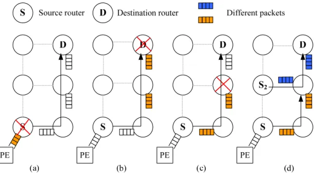
To ensure the success of packet delivery in a NSI-mesh network, we should prevent the occurrence of all the following four cases:
(i). Source router is not serving
(ii). Destination router is not serving
(iii).Any router on selected path is not serving
(iv).Any required channel on the selected path is occupied (Head-of-
Line, HoL blocking)
The first one, as shown in Fig. 2-5(a), the source router is fully throttled. The second one, as shown in Fig. 2-5(b), the destination router is fully throttled. The third case, as shown in Fig. 2-5(c), some of the router on the routing path is fully throttled.
The last one is shown in Fig. 2-5(d), where the channels on the routing path are blocked by other blocked packets, and we take vertical dimension as example. (iv) is also emerges in the horizontal dimension, and we call (iv) as Head of Line Blocking (HoL).
16
Fig. 2-5 Problem of usual reactive routing: (a) Source router is not serving. (b) Destination router is not serving. (c) Any router on selected path is not serving. (d) Head of line Blocking.
We know routing emerges in network layer, and the congestion also emerges in network layer. We should try to solve the problems (i)-(iv) by considering applying layers of NoC. We know about throttling influences performance and should minimize the influence of throttling, but we cannot solve the problem caused by run- time thermal management only by network layer. We should consider other layers to help solve our problem. For problem (iv), we can solve in flow control layer (data link layer), like virtual channel or increasing buffer or link, to prevent packet block by other packet. And we know if we solve other three problems, we can eliminate this HoL blocking problem. If we eliminate other three problems, HoL blocking will sometimes emerge, and it block for up to hundreds of cycles, which is different to 107 cycles caused by run-time thermal management. If we block for 107 cycles, it will decrease our performance a lot. (i) to (iii) is our consideration, because it influences our performance more than (iv).
17
For application layer, it consider all the system and algorithm what it should execute. It does not need to consider these detail problems, so we exclude it. For physical layer, it is too detailed for use to consider this problem, so we still exclude it.
For transport layer, we can solve tow problems (i) and (ii). For transport layer, if we have source router and destination router status, we can understand source or destination router is serving or not. However, we can determine transmit packet to network layer or not in transport layer. We can eliminate these two problems in transport layer.
For the rest problem (iii), we know throttling problem emerge in network layer, so we consider solving this problem in network layer previously. Nevertheless, we cannot solve it only in network layer. Because we cannot predict next router routing path with no throttled router, we cannot guarantee that the routing path has no throttled routers. Additionally, we cannot see all NoC buffer and router status to determine which routing path is routable, because it is source routing, and it differs from our constraints and goal. We can take Fig. 2-6 as an example.
Fig. 2-6 (a) (iii) situation cannot guarantee routing path which router choose is routable. (b) Block other packet, which is same as (iv).
18
In Fig. 2-6(a), from source router, we know the router in east is not throttled, so we may go eastern router. But after we arrive at eastern router, we only have northern router to route, and it is throttled. So packet is blocked by throttled router, and it will be block for 107 cycles, and the other packet is blocked by this packet. As shown in Fig. 2-6(b), the packet blocked by throttled routers will block other packets, and the congestion tree will grow soon to whole network.
To completely remove the case of (iii), we have to jointly consider the available information of the network layer and transport layer. Here we choose the style of distributed routing instead of source routing for performance consideration. Although traditional source routing can be applied in this scheme, the computation overhead of source routing for optimizing performance of NSI-mesh is too high. Besides source routing cannot balance the loading of the network by adapting the network information as adaptive routing. If the topology of the network is far from regular mesh, it would be difficult to use source routing. The small changing interval and large range of inactive number characteristics of throttled NSI-mesh make conventional routing algorithms infeasible. The routing algorithms for irregular-mesh [34] are not feasible owing to the non-stationary characteristics. Besides, the regulations of the location of oversized-IP make the conventional algorithms infeasible because throttling may be required for all the upper layer routers. Moreover, the offline optimization effort for routing in irregular-mesh is not affordable for the online computation of the throttled NSI-mesh. The fault-tolerant routing algorithms those detour packets from faulty routers could be candidates. However, the characteristics of faulty NSI-mesh and throttled NSI-mesh are very different. The
19
number of faulty router is non-decreasing but usually small. Besides, the interval of topology transformation in faulty NSI-mesh is much longer and unpredictable. The topology changing of faulty NSI-mesh is occurred after detection, testing, and reconfiguration of the system. Usually the latter two operations are even done in the reboot sequence, which makes the problem going back to traditional offline irregular- mesh. Similarly the regulations of the location of faulty routers make the conventional fault-tolerant routing algorithms infeasible because throttling may be required for all the upper layer routers.
If we use transport layer to solve (iii), it still not work. If we know status of source and destination router, we still cannot guarantee the packet can route to destination router successfully. When a packet inject form transport layer to network layer, we think it can transmit to destination router in previous knowledge, excluding congestion or head–of–line blocking. It can work in normal NoC, but it fail in throttled NoC.
We can conclude throttling problem emerge in network layer, but we cannot solve (iii) only in network layer or transport layer. If we cannot solve (iii) situation, the whole network will stop for a period of time. Therefore, we should combine these two layers to solve the (iii). See in Fig. 2-7.
Fig. 2-7 Transport layer and network layer operation.
20
2.5 Summary
We reference related works for thermal-aware 3D NoC, and discover a new problem: Non-Stationary Irregular Mesh (NSI-Mesh). We find four problems of delivery packets, and also show how to solve them by using transport layer and network layer. Finally, we conclude that we need to joint transport layer and network layer to solve the problems caused by NSI-Mesh.
21
Chapter 3
Transport-Layer Assisted Routing
Transport-layer assisted routing is composed of the transport layer assisted routing schemes and the dual-mode routing algorithms. Transport layer shares topology information with network layer for high performance in NSI-mesh. Network layer follows the initial routing decision provided by transport layer, and tries to balance the lateral traffic loading. In this chapter, we introduce the proposed Transport-Layer Assisted Routing (TLAR) schemes and algorithms.
3.1 Operation Flow of Transport-Layer
The proposed operation flow of Transport-layer assisted routing is shown as following.
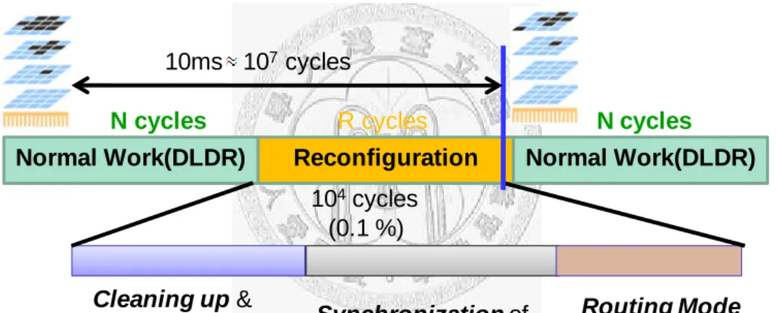
The system of 3D NoC is switching between the normal stage and the reconfiguration stage. In normal stage the 3D NoC works as usual irregular or regular mesh network. In this stage, we assume distributed thermal sensing mechanism is embedded in the network for each router to obtain its own temperature, and each router has a timer for synchronizing their operation stages. After N-cycle normal stage, the network enters the R-cycle reconfiguration stage. The reconfiguration stage means that we should prepare some management and controller, which let 3D NoC remains execution in normal work. In comparison with the cycle number in normal operation stage, the cycle number required for reconfiguration is very small. Here we
22
assume the network is operated at 1GHz. In each 10ms interval, 104 cycles is absolutely sufficient for each tile to reconfigure, and N is around 107. The reconfiguration stage only occupies 0.1% of the total available time, so the overhead of reconfiguration is negligible. If the interval is 100ms, the overhead is 0.01%, which is more negligible. The reconfiguration stage, shown in Fig. 3-1, consists of three sub-stage: (i) cleaning up and policy determination; (ii) synchronization of topology information; (iii) routing mode checking and throttling. The detail is described as following:
Normal Work(DLDR) Reconfiguration Normal Work(DLDR) N cycles R cycles
N cycles
Cleaning up &
Policy
Determination
Synchronization of Topology Information
Routing Mode Determination
& Throttling 10ms 107 cycles
104cycles (0.1 %)
Fig. 3-1 Network states and operation stages in transforming topology for run-time thermal management.
(i) Cleaning up and policy determination: In order to make sure packet
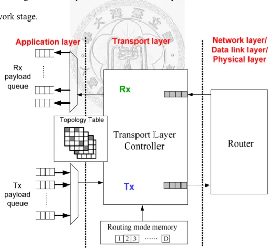
transport t0 destination router successfully in next normal work, the network has to be cleaned up before topology changing. In this stage, the packetization of the payloads from transport layer to network layer is paused. As shown in Fig. 3-2, the payloads stay in the transmitter payload queue. In this stage, we should not only stop transmitting packet form transport layer to network layer,
23
but also deal with the rest packet still in network layer. It means transmitter packet queue will become empty after a small period of time. In the meanwhile, the distributed thermal-aware controller in each tile should determine the throttling of the router within the tile for the next normal stage.
The implementation of thermal-aware management can be in the transport layer controller or in the application layer as a software routine. No matter which layer the policy is determined, the application layer and transport layer share the information of control policy of this tile. The important thing for us is that the new throttling emerges for the next normal work stage, and we should guarantee no packet still in network layer is blocked in next normal work stage.
Fig. 3-2 Block diagram of transport layer in the tile of thermal-aware 3D NoC.
24
(ii) Synchronization of topology information: If we trigger throttling, we
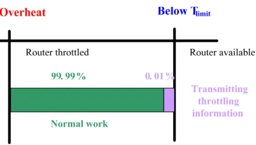
should let every router in 3D NoC know which router is throttled and how the topology change in next normal work. In this stage, all routers have to transmit packets containing their throttling information to all their upstream and downstream routers. No matter in current normal stage the router is fully throttled or not, it is not throttled in this sub-stage. Because all the routers are not throttled in this sub-stage, the network is regular mesh in each layer. We can see topology table in Fig. 3-2 which is shared by application layer and transport layer. In this topology table, each router requires one bit for representing the state of each router in the next normal stage. If a router is fully throttled in the next normal stage, the corresponding bit will be toggled to inactive. Otherwise the bit will be active. Then the information of topology is synchronized to each tile. The technology of transmitting throttling information is not our consideration. Because the throttling is triggered by 10ms, the transmission of throttling information is just up to hundreds of cycles, and it is just 0.1% of 10ms. We have 99.99% time of normal work, and we collect correct throttling information and make correct routing selection. We can see in Fig. 3-3, so the transmission of throttling information is not our problem in NSI-mesh.
25
Fig. 3-3 Required time of transmitting throttling information.
(iii) Decisions of routing mode and throttling: In this stage, the throttling of
router is applied now. If all routers in 3D NoC are not throttled, the routing is just like in regular mesh. But when throttling is trigger, we need determine routing mode for transmission toward each destination router in the transport layer. If the source router is throttled, the payload will stay in the transmitter payload queue. If the source router is not throttled, we should execute transport-layer assisted routing (TLAR) to check all routing mode of destination router for ensuring no packet is blocked by run-time thermal management. After executing TLAR, network goes back to the normal stage, and the packet injection continues for the tile where the router is not throttled.
26
3.2 Proposed Framework of Transport Layer Assisted Routing
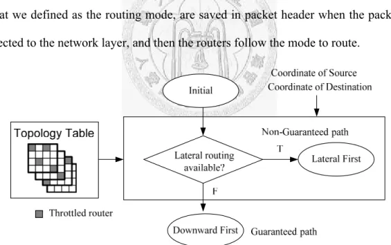
To correctly select a path that makes packet delivery success, we propose the Transport Layer Assisted Routing Scheme (TLAR) for packets with non-fully throttled source and destination routers. The routing in TLAR is based on our previously proposed downward routing, which is a combination of vertical routing and lateral routing. The key idea of TLAR is that the throttling information in transport layer is used to assist the selection of layer for lateral routing and the decision of routing algorithm in network layer. The selection and decision results, what we defined as the routing mode, are saved in packet header when the packet is injected to the network layer, and then the routers follow the mode to route.
Fig. 3-4 Framework of proposed transport layer assisted routing scheme. The determination of lateral routable relies on the throttling information in transport layer.
Fig. 3-4 shows the flow chart of path selection in TLAR. The checking of lateral path is done during the reconfiguration stage for each destination in the transport
27
layer above the source router. For the packet which is going to a lateral routable destination, it is routed first laterally. Otherwise downward path is selected because it is guaranteed routable. As shown in Fig. 3-2, the overhead of TLAR is the small memory for storing the checking results as the routing modes. In normal operation, the transport layer controller reads the routing mode from the memory and set the packetizer. Then the payload is packetized with the routing mode specified in header..
Fig. 3-5 Path selection of proposed transport layer assisted routing scheme.
In TLAR, packets change their z-location only when it is at the source or the destination xy-location, and the selection of routing path is dependent on the relative vertical location of source and destination, as shown in Fig. 3-5. As mentioned before, the routers in the bottom layer are never throttled. Therefore if source and destination routers are not fully throttled, the vertical path and lateral path through bottom layer will be guaranteed routable. If there is no fully throttled router on the non-guaranteed path, TLAR chooses this path for lateral routing. Owing to the bandwidth required for downward routing, TLAR prevents to choose layers below source router and above the bottom layer for lateral routing. Checking if the lateral path is routable for these layers also multiples of the computation overhead for path selection. Any lateral path locates above source router is forbidden owning to the limitation of turn model. As the proof in our previous works [33], the combined routing is deadlock-free if the lateral routing is deadlock-free and we remove the {UN, UE, US, UW} turns.
28
3.3 Proposed Algorithm: Downward-Lateral Deterministic Routing (DLDR)
The proposed 3D routing algorithm in TLAR is the combination of downward routing and a deterministic routing (DLDR). The downward routing is used for moving packets up and down in the vertical direction. The lateral deterministic routing is used for routing packets in the lateral direction. The path diversity is two because we can select to route in the source layer or the bottom layer. For reducing the computational complexity of checking rout ability, we adapt XY routing, a dimension-ordered routing (DOR), as the deterministic routing.
Fig. 3-6 (a) TLAR examples, and (b) checking dependency.
An example of routability is shown in Fig. 3-6(a). There are three kinds of destination routers. First, the gray blocks are throttled destinations. The messages toward these destinations are kept in message queue until destinations are routable.
Otherwise, the packets will be blocked in the network because the destination router is not active. Second, the white blocks are routable destinations with XY routing; an example path is shown by the green line. Third, the pale blue blocks are destinations
29
those are only downward-routable. An example of the path of downward routing is shown by the dotted line. Conclusively, if the path is lateral-first routable, the packet first traverses through the lateral path in the source layer. Then, the packet goes up or down to the destination router. Otherwise, the downward path is the only path, so the packet first traverses to the bottom layer and is routed laterally in the bottom layer.
Then, the packet goes up to the destination router.
When topology is changed, the routing mode must be decided again for each destination, and the decisions are saved in the network interface. The controller in transport layer checks if there is any fully-throttled router on the paths based on the topology table. The checking of the routability of all destinations in the source layer can be done by using the incremental breadth-first search (BFS) style, as shown in Fig. 3-6(b). The dependency is based on XY-routing, and the prerequisites that a node routable is its previous node also routable. For an 8x8x4 network, the operation is completed in 63 cycles.
3.4 Summary
In this chapter, we propose the Transport-Layer Assisted Routing (TLAR) scheme. TLAR can make sure the delivery packets can reach destination router successfully, and the operation flow and checking of TLAR is also described here.
Based on TLAR, we propose DLDR for sending packets with XYZ routing or downward routing.
30
Chapter 4
Performance Evaluation
4.1 Setting of Simulation Environmentst
Currently there is no real chip implementation of 3D NoC systems, so we start from modeling the 2D NoC system implemented in [30] and stack it to multiple layers. For network simulation, we start from Noxim [28], and we extend it to the third dimension. For temperature simulation, we use Hotspot [29], and We adopt the tile geometry and power model of Intel’s 80-core processor [30]. We first add the model of basic 3D router and the Dimensionally-Decomposed (DimDe) router [23], and modified Noxim to generate the 3D-NoC architecture and the floorplan based on user-defined parameters of dimension. During network traffic simulation, a power trace is generated based on the power model of the NoC. The power trace and physical floorplan are input to the thermal model. In the proposed simulator, the tile geometry and power model are based on Intel’s 80-core chip. Fig. 4-1 shows the construction of the co-simulation model and Fig. 4-2 shows the floor plan as we used.
We adopt the basic wormhole flow control and use random arbitration for switch allocation
We construct 3D 8×8×4 NoC, and the packet length is randomly from 2 to 10 flits. The queue depth of each input channel is 16 flits, and the link level flow control protocol is full hand-shake request and ack. Because TSVs generally have high bandwidth, a crossbar-based vertical connection is assumed in our 3D router [10]. For each tile in the NoC, the tile area is 2.0mm × 1.5mm and the router area is 0.65mm ×
31
0.53mm.
Fig. 4-1 Framework of co-simulation platform.
Fig. 4-2 Construction of the model of a 4x4x4 3D NoC with simplified tile model from. [30]
To keep the performance indices representative and comparison as fair as possible, several modifications of the simulator are required for modeling the TLAR.
In Noxim[28], the statistics of received packet number, packet latency, and network throughput are based on the received packets during the simulation period while the network is assumed stable. The payloads toward the fully throttled destinations are hold in the transport layer and not packetized, and only the deliverable payloads are packetized and injected to the network. Originally the injection rate is simulated by
Network Model Noxim (3D)
Power Model Intel 80‐core NoC
Thermal Model HotSpot (3D) Traffic Activity
Power trace
Temperature
32
generating Poisson arrived packets of given traffic distribution of destinations over the network. The network injection rate of the active routers follows the index by escaping the packets to the throttled destinations and regenerating more packets toward non-throttled destinations. Because we assume application layer and transport layer share the topology information, the packet injection process of the throttled router is paused until it is not throttled. In this setting, the total injection rate of the network can be obtained by multiplying injection rate and the number of the active routers, and the statistics of performance indices are not affected by throttling.
In this chapter we show the performance of the proposed TLAR algorithms.
We use two throttling cases of vertical throttling: (a) 1 throttled router, and (b) 2 2x2 throttled region. In case (a), the one throttled routers is located in the center of the most top layer of the 8x8x4 network. In case (b), 8 1x1x3 pillars are throttled on the diagonal line of the upper three layers of the 8x8x4 network. And they are shown in Fig. 4-3.
Fig. 4-3 Throttling cases: (a) 1 router (b) 2 2*2*3 routers.
33
4.2 Traffic balance and rate of transmitting packet under different routings
First we use statistical traffic load distribution (STLD) [34] and decision distribution to show the network loading. All the experiment in Fig. 4-4 and Fig. 4-5 use the same injection rate that makes average latency of TLAR-DLDR twice the zero load latency.
Fig. 4-4(a) shows the STLD of the baseline downward routing and Fig. 4-4(b) shows the TLAR-DLDR algorithm, which is the combination of downward routing and TLAR. Though there is only one router throttled in the network, some packets have to be routed downward through the bottom layer. The congestion degree of DLDR in the bottom layer is reduced and the loading of the work is more balanced by using proposed DLDR. The packets in the upper layers are more balanced, because the congestion in the bottom layer is relaxed. We use Fig. 4-4(c) to show distribution of the routing mode decision. In DLDR scheme, 80% packets are determined to route on the deterministic paths in the source layers and 20% packets are routed in the downward mode. We can prove we decrease the rate of downward routing by proposed DLDR.
34
0%
20%
40%
60%
80%
100%
XY (Lateral‐FIRST) Downward (Z‐First)
0
(a) (b) (c)
Downward TLAR-DLDR
Fig. 4-4 (a) Statistical traffic load distribution (STLD) of conventional design; (b) STLD of proposed TLAR framework with DLDR algorithm; (c) latency vs. network injection rate.
Fig. 4-5 shows similar results when we increase the number of disconnected throttled routers and the size of the region. We increase the number of throttled routers from 1 router to 24 routers. The congestion degree of downward in the bottom layer is still larger than DLDR, because downward cannot balance the loading of the bottom layer. The packets the upper layers are more because the congestion in the bottom layer is relaxed by using of our proposed DLDR algorithm. We use Fig. 4-5(c) to show distribution of the routing mode decision. In DLDR scheme, 40% packets are determined to route on the deterministic paths in the source layers, and 60% packets are routed in the downward mode. The DLDR algorithm has fewer packets choosing the downward mode, so DLDR is more vertical balanced than downward routing.
35
0%
20%
40%
60%
80%
100%
XY (Lateral‐FIRST) Downward (Z‐First)
Fig. 4-5 (a) Statistical traffic load distribution (STLD) of conventional design; (b) STLD of proposed TLAR framework with DLDR algorithm; (c) latency vs. network injection rate.
We use Table 4-1 to show the statistics of the statistical traffic load distribution (STLD). As we can see, the mean packet number is increased by adopting the TLAR scheme and both total and inter-layer standard deviations are reduced by applying DLDR algorithm. The statistics is corresponded to the performance simulations, which are shown in Fig. 4-6. In the case of 1 throttled router, there are 255 active routers injecting packets to the network. For the case in Fig .4-3(b), only 232 routers are active. These active routers can transmit (receive) the packets to(from) the network. Because of the more balanced loading of the network, the DLDR has better performance than the baseline algorithm downward routing in both 1 and 2 2x2x3 throttling cases. The throughput in Fig. 4-6(a) is improved by 95% by adopting the
36
DLDR algorithms. In Fig. 4-6(b), the throughput is improved by 70%. We can see our proposed algorithm DLDR is outperforming than downward routing.
Table 4-1 Statistics of statistical traffic load distribution.
One Throttled router Two 2x2x3 Throttled Pillars
Downward TLAR-DLDR Downward TLAR-DLDR
Mean
L1 330.75 798.6 149.7 1113.5
L2 403.05 1598.6 147.4 1100.7
L3 546 2004.2 148.2 1110.4
L4 6495.24 5208.84 4960.8 3280.9
Total 2372.55 2633.76 1476.0 1707.6
Stdv.
L1 27.9 11.85 12.8 74.9
L2 31.2 15.3 12.0 70.8
L3 44.85 98.1 12.2 97.3
L4 2067.6 1446 280.2 185.3
Total 3097.44 2190.84 2160.5 980.4
Inter-Layer 2821.28 2002.88 2406.2 1086.4
0 50 100 150 200 250 300
0 5 10 15 20 25
Downward TLAR‐DLDR
0 50 100 150 200 250 300
0 5 10 15 20 25
Downward TLAR‐DLDR
Fig. 4-6 Average latency vs injection rate with (a) one router throttled and (b) two 2x2x3 pillars throttled.
37
4.2.1 Network Sustainability and Degree of Graceful Degradation
Here we show the network sustainability and the degree of graceful degradation.
Network sustainability describes the total throughput provided by the network while some parts of the network are not working. If a router is throttled, it cannot provide the bandwidth for packet delivery. With higher network sustainability, the 3D NoC can provide larger throughput when there are routers fully throttled. Because we cannot simulate all throttling cases, we simulate extreme cases from on throttled routers to 7x7x3 throttled routers, as shown in Fig. 4-7. As shown in Fig. 4-8, all algorithms degrade as the size of throttled region increases. Here we want to observe the throughput degradation in the different case of vertical load balancing of different irregular topologies occurred in NSI-mesh. We start from the 1x1x1 throttling case and then extend to the 7x7x3 throttling case. All the throttled regions are located in the center of the xy-plane. In all cases, the DLDR algorithms have better performance the conventional reactive downward routing. In comparison with conventional reactive downward routing, the proposed TLAR-DLDR can averagely improve the sustainable throughput from 85.5% to 48%.
1x1x1 1x1x2 1x1x3 2x2x3 4x4x3 6x6x3 7x7x3
Fig. 4-7 Different throttling cases.
38
0 5 10 15 20 25 30 35 40 45
1x1x1 1x1x2 1x1x3 2x2x3 4x4x3 6x6x3 7x7x3 Network Throughput (Flits/Cycles)
Size of throttled region
Downward TLAR‐DLDR
Fig. 4-8 Network sustainability of NSI-mesh 3D NoC, uniform traffic offered.
4.2.2 Run-Time Temperature and Throughput
Here we show the real case for simulating TLAR in run-time thermal management. The simulation setup is as same, and the only difference is that we do not fixe location of throttled routers in simulation. Thermal-Aware Vertical Throttling (TAVT) is adopted in RTM to throttle overheat routers, and TLAR will detect throttled routers and detour them. As shown in Fig. 4-9, the total simulation cycle in network simulator is M+1000K cycles. The total simulation time for temperature is 10 seconds, and is divided into 1000 10ms intervals for observing the transient-state temperature. For each 10ms interval, our network simulator uses K cycles to evaluate the transient power. The network simulator first runs for M cycles to warm up the network, and the thermal simulator setups the ambient temperature Tamb and initializes the temperature distribution T0. For each 10ms interval, the network simulator uses K cycles to estimate the power distribution, which is denoted as P(t ,t+10). Then the thermal simulator is called to estimate the transient-state temperature Tt+10 based on given short-term power distribution P(t ,t+10) and the
39
beginning temperature distribution Tt. In this simulation, K=50000 cycles for reaching steady state of traffic between thermal checking, and we focus on transient temperature and throughput of each interval.
Fig. 4-9 Mutual-coupling co-simulation for throughput and temperature evaluation.
We show the temperature and numbers of throttled routers from 7.1s to 7.6s.
As shown in Fig. 4-10(a), the transient temperature is below thermal limit, because TAVT effectively controls the temperature. The number of throttled routers means the changing of topology, from regular to irregular and back to regular. The throughput of downward routing is shown in Fig. 4-10(b), and the average throughput between 7.1s to 7.6s is 15.4 (Flits/Cycles).
Fig. 4-11(a) shows the temperature and throughput of TLAR with same simulation setup. The average temperature of TLAR is 0.15°C more than downward routing, which is relatively small to changing of temperature. However, as shown in Fig. 4-11(b), average throughput of TLAR is 25.4 (Flits/Cycles), which is improved 66% in comparison with downward routing. The temperature of TLAR is a little
40
higher than traditional downward results from the larger throughput. TLAR delivery more packets, so the power is higher. Therefore the transient temperature is high, too.
0 10 20 30 40 50
92 94 96 98 100 102
7.1 7.2 7.3 7.4 7.5
# of throttled routers
Temperature(°C)
Time(s)
Downward_temp Downward_throttling
0 10 20 30 40 50
7.1 7.2 7.3 7.4 7.5
Throughput(Flits/Cycles)
Time(S) (a)
(b)
(c)
Downward Routing
Avg. Temp.(°C) 99.35
Avg. # of Throttling 9.5
Avg. Throughput 15.3
Fig. 4-10 (a) Temperature and numbers of throttled routers of downward routing. (b) Throughput of downward routing. (c) Statistics of downward routing.
41
0 10 20 30 40 50
92 94 96 98 100 102
7.1 7.2 7.3 7.4 7.5
# of throttled routers
Temperature(°C)
Time(S)
TLAR_temp TLAR_throttling
0 10 20 30 40 50
7.1 7.2 7.3 7.4 7.5
Throughput(Flits/Cycles)
Time(S)
TLAR
Avg. Temp.(°C) 99.5
Avg. # of Throttling 7.6
Avg. Throughput 25.4
Fig. 4-11 (a) Temperature and numbers of throttled routers of TLAR (b) Throughput of TLAR. (c) Statistics of TLAR.
42
4.3 Summary
In this chapter, we see the performance results of TLAR. For traffic loading distribution, the proposed TLAR can balance vertical loading than downward routing because of more lateral packets used for routing. The throughput is also higher than downward routing for fixed or non-fixed throttled region of routers. Finally, we simulate TLAR on real case. Although TLAR has a little higher temperature, the throughput result is better than downward routing.
43
Chapter 5 Architecture Design for
Transport-Layer Assisted Routing
For successful data delivery and performance consideration, we propose transport layer assisted routing (TLAR) scheme. Here we propose a low cost and low latency architecture of TLAR.
5.1 Traditional Architecture and Dataflow
NoC is composed of five layers [33]: Application layer, Transport layer, Network layer, Data link layer and Physic layer. For architecture design, we focus on transport layer and network layer, because we use transport layer to assist network layer for routing decision, and we should consider are overhead comparing to traditional design. The implementation is composed of a router, which transfer hop by hop, and a network interface (NI), which implements the interface to the IP modules.
The traditional architecture is show in Fig. 5-1.
Network interface is allocated in transport layer, as shown in Fig. 5-2.
Network interface (NI) is the component that provides the conversion of the packet- based communication of the NoC to the higher-level, which communicate between application layer and network layer. Ni packetize message from application layer to packet transmitting to network layer. In Fig. 5-1, this is the traditional NI + router, and it can maintain traditional function of network interface, but cannot maintain the transport-layer assisted routing.
44
Fig. 5-1 Architecture of network interface and router in the traditional 3D NoC.
Routers deal with packet form network interface, and choose routing path to route packet to destination router, which transmit flits rather than packets, as shown in Fig. 5-2. Because the transport layer provides packets to network layer, routers should find routing path to destination hop by hop. Because traditional NI and router cannot maintain TLAR scheme, we propose TLAR network interface and dual mode router architecture for TLAR scheme, and we discuss them in following sub-chapter.
45
Fig. 5-2 Data flow between application layer, transport layer and network layer.
5.2 Network Interface Design
5.2.1 Control Logic and FSM
We know network interface is established in transport layer, and we should maintain original function of network interface and our proposed transport-layer assisted routing. Because traditional network interface cannot maintain TLAR scheme, we propose TLAR network interface, as shown in Fig. 5-3. We can divide our network interface to four major parts:
Baseline Datapath and Tx/Rx Queues (Tx/Rx): Tx deals with the message from application layer and packetize the payloads in to packets to network layer. In contrast, Rx receives packet from network layer, de-packetizes, and combines to message to application layer. Tx and Rx require data queue for storing payloads and packets respectively.
Topology Table (TT): This table stores 1-bit throttling information of each destination, and updates on each topology change. Application layer and
46
transport layer share this information. TT is required for all NSI-mesh networks to solve the problem of (i) Source router is not serving and (ii).
Destination router is not serving. Direct implementation of TT requires XYZ bits for an X-by-Y-by-Z 3D NoC.
Routing Mode Memory (RMM): RMM is required to reduce the timing overhead of checking routing mode for each packet. The mode for each destination is checked once as topology changing and stored in RMM. Before injecting a packet to network layer, the correspond routing mode is queried from RMM. Direct implementation of RMM also requires XYZ bits for an X- by-Y-by-Z 3D NoC.
Control Logic (CL): In baseline NI, CL controls the functionality of Tx/Rx.
For TLAR network interface, CL also includes the TLAR routing mode checking, and controllers for reconfiguring the topology table. Finite-State Machines (FSMs) are to implement in CL for timing and signal controls.
Fig. 5-3 Proposed architecture of TLAR.
47
5.2.2 Techniques of Memory Reduction
To prevent area overhead, we propose two memory reduction techniques to reduce area. The proposed memory reduction techniques are based on the three characteristics of NSI-mesh of TAVT-RTM: 1) TAVT never throttles the router in the bottom layer; 2) if a router is throttled, all the routers above it are throttled; 3) if a router is not throttled, all the routers below it are not throttled.
For topology table (TT), if the throttling can be applied to all routers, 1-bit information is required for each destination in TT. Because of the throttling characteristics (2) and (3), we only need to store which layer is the top of the non- throttled routers, as the green nodes shown in Fig. 5-4(a). Therefore, the number of bits can be reduced from XYZ to XY log2(Z) , as shown in Fig. 5-4(b) and Fig. 5-4 (c). For example, for (x,y,z) direction = (N,M,K) of 3D NoC, we originally need N*M*K bits to store topology table(only one bit to indicate throttling or not). By introducing the characteristic of throttling, we only need N*M*log2(K) bits. There are some examples shown in Table 5-1.
48
Fig. 5-4 (a) Reduce the size of topology table by storing the first non-throttled layer for each XY location. (b) Direct implementation. (c) Implementation with proposed TT reduction technique.
Table 5-1 Topology table comparison.
For NxMxK 3D NoC
Original topology table (N*M*K)
Improved topology table (N*M*(log2k))
Reduction
8x8x2 3D NoC 128 64 50%
8x8x4 3D NoC 256 128 50%
8x8x8 3D NoC 512 192 62.5%
The other memory reduction is about routing mode memory. For routing mode memory (RMM), TLAR only requires bits to store the routing modes for all
![Fig. 1-1 shows the trend of the on-chip interconnections [3]. As the increases of IPs, the complexity of on-chip interconnections increases rapidly](https://thumb-ap.123doks.com/thumbv2/9libinfo/9607707.633407/13.892.141.723.829.1046/shows-trend-interconnections-increases-complexity-interconnections-increases-rapidly.webp)

![Fig. 1-5 The growth of cooling cost. [20]](https://thumb-ap.123doks.com/thumbv2/9libinfo/9607707.633407/18.892.261.643.131.378/fig-growth-cooling-cost.webp)