A - 1
SAFETY PRECAUTIONS
(Always read these instructions before using this equipment.)
Before using this product, please read this manual and the relevant manuals introduced in this manual carefully and pay full attention to safety to handle the product correctly.
The instructions given in this manual are concerned with this product. For the safety instructions of the programmable controller system, please read the CPU module user's manual.
In this manual, the safety instructions are ranked as "DANGER" and "CAUTION".
Note that the CAUTION level may lead to a serious consequence according to the circumstances.
Always follow the instructions of both levels because they are important to personal safety.
Please save this manual to make it accessible when required and always forward it to the end user.
[Design Precautions]]
DANGER
Some failures of the GOT, communication unit, communication board or cable may keep the outputs on or off.
An external monitoring circuit should be provided to check for output signals which may lead to a serious accident.
Not doing so can cause an accident due to false output or malfunction.
If a communication fault (including cable disconnection) occurs during monitoring on the GOT, communication between the GOT and PLC CPU is suspended and the GOT becomes inoperative.
For bus connection : The CPU becomes faulty and the GOT becomes inoperative.
For other than bus connection : The GOT becomes inoperative.
A system where the GOT is used should be configured to perform any significant operation to the system by using the switches of a device other than the GOT on the assumption that a GOT communication fault will occur.
Not doing so can cause an accident due to false output or malfunction.
Do not use the GOT as the warning device that may cause a serious accident.
An independent and redundant hardware or mechanical interlock is required to configure the device that displays and outputs serious warning.
Failure to observe this instruction may result in an accident due to incorrect output or malfunction.
DANGER Indicates that incorrect handling may cause hazardous conditions, resulting in death or severe injury.
Indicates that incorrect handling may cause hazardous conditions, resulting in medium or slight personal injury or physical damage.
CAUTION
A - 2
[Design Precautions]
[Mounting Precautions]]
DANGER
Incorrect operation of the touch switch(s) may lead to a serious accident if the GOT backlight is gone out.
When the GOT backlight goes out, the display section turns black and causes the monitor screen to appear blank, while the input of the touch switch(s) still remains active.
This may confuse an operator in thinking that the GOT is in “screensaver” mode, who then tries to release the GOT from this mode by touching the display section, which may cause a touch switch to operate.
Note that the following occurs on the GOT when the backlight goes out.
The monitor screen disappears even when the screensaver is not set.
The monitor screen will not come back on by touching the display section, even if the screensaver is set.
CAUTION
Do not bundle the control and communication cables with main-circuit, power or other wiring.
Run the above cables separately from such wiring and keep them a minimum of 100mm apart.
Not doing so noise can cause a malfunction.
DANGER
Before installing or removing the GOT to or from the control panel, always switch off the GOT power externally in all phases.
Not doing so can cause the GOT to fail or malfunction.
Before loading or unloading the communication board, communication unit or memory board to or from the GOT, always switch off the GOT power externally in all phases.
Not doing so can cause the unit to fail or malfunction.
CAUTION
The GOT should be used in the environment given in the general specifications of the GOT user's manual.
Not doing so can cause an electric shock, fire, malfunction or product damage or deterioration.
When mounting the GOT to the control panel, tighten the mounting screws in the specified torque range.
Undertightening can cause the GOT to drop, short circuit or malfunction.
Overtightening can cause a drop, short circuit or malfunction due to the damage of the screws or
the GOT.
A - 3
[Mounting Precautions]
[Wiring Precautions]
CAUTION
When loading the communication board or communication unit to the GOT, fit it to the connection interface of the GOT and tighten the mounting screws in the specified torque range.
Undertightening can cause a drop, failure or malfunction.
Overtightening can cause a drop, failure or malfunction due to the damage of the screws or unit.
When loading the memory board into the GOT, load it into its corresponding GOT slot and tighten the mounting screws in the specified torque range.
Undertightening can cause a malfunction due to a poor contact.
Overtightening can cause a malfunction due to the damage of the screws or the GOT.
When loading the PC card into the GOT, insert and push it into its corresponding GOT slot until the PC card eject button comes up.
Not doing so can cause a malfunction due to a poor contact.
Before loading or unloading the PC card to or from the GOT, set the memory card access switch to the OFF position.
Not doing so can cause the PC card data to be corrupted.
When taking out the PC card, hold it with one hand and remove.
If removed without a hand support, the PC card may drop, resulting in breakage or damage.
DANGER
Before starting wiring, always switch off the GOT power externally in all phases.
Not doing so may cause an electric shock, product damage or malfunction.
CAUTION
Please make sure to ground FG terminal, LG terminal, and protective ground terminal of the GOT power supply section by applying Class D Grounding (Class 3 Grounding Method) or higher which is used exclusively for the GOT.
Not doing so may cause an electric shock or malfunction.
Correctly wire the GOT power supply section after confirming the rated voltage and terminal arrangement of the product.
Not doing so can cause a fire or failure.
Tighten the terminal screws of the GOT power supply section in the specified torque range.
Undertightening can cause a short circuit or malfunction.
Overtightening can cause a short circuit or malfunction due to the damage of the screws or the GOT.
Exercise care to avoid foreign matter such as chips and wire offcuts entering the GOT.
Not doing so can cause a fire, failure or malfunction.
A - 4
[Wiring Precautions]
[Test Operation Precautions]
[Startup/Maintenance Precautions]
CAUTION
Plug the bus connection cable by inserting it into the connector of the connected unit until it
"clicks".
After plugging, check that it has been inserted snugly.
Not doing so can cause a malfunction due to a contact fault.
Plug the communication cable into the connector of the connected unit and tighten the mounting and terminal screws in the specified torque range.
Undertightening can cause a short circuit or malfunction.
Overtightening can cause a short circuit or malfunction due to the damage of the screws or unit.
DANGER
Before performing test operation (bit device on/off, word device's present value changing, timer/
counter's set value and present value changing, buffer memory's present value changing) for a user-created monitor screen, system monitoring, special module monitoring or ladder monitoring, read the manual carefully to fully understand how to operate the equipment.
During test operation, never change the data of the devices which are used to perform significant operation for the system.
False output or malfunction can cause an accident.
DANGER
When power is on, do not touch the terminals.
Doing so can cause an electric shock or malfunction.
Before starting cleaning or terminal screw retightening, always switch off the power externally in all phases.
Not switching the power off in all phases can cause a unit failure or malfunction.
Undertightening can cause a short circuit or malfunction.
Overtightening can cause a short circuit or malfunction due to the damage of the screws or unit.
CAUTION
Do not disassemble or modify the unit.
Doing so can cause a failure, malfunction, injury or fire.
Do not touch the conductive and electronic parts of the unit directly.
Doing so can cause a unit malfunction or failure.
A - 5
[Startup/Maintenance Precautions]
[Backlight Changing Precautions]
[Disposal Precautions]
CAUTION
The cables connected to the unit must be run in ducts or clamped.
Not doing so can cause the unit or cable to be damaged due to the dangling, motion or accidental pulling of the cables or can cause a malfunction due to a cable connection fault.
When unplugging the cable connected to the unit, do not hold and pull the cable portion.
Doing so can cause the unit or cable to be damaged or can cause a malfunction due to a cable connection fault.
DANGER
Before changing the backlight, always switch off the GOT power externally in all phases (when the GOT is connected to the bus, the PLC CPU power must also be switched off externally in all phases) and remove the GOT from the control panel.
Not switching the power off in all phases may cause an electric shock.
Not removing the unit from the control panel can cause injury due to a drop.
CAUTION
When replacing the backlight, use the gloves.
Otherwise, it may cause you to be injured.
If you should directly touch the plated area of the main unit case with hand, be sure to wipe off the fingerprint and so on, and install the main unit case.
Otherwise, it may cause a trouble or malfunction.
Start changing the backlight more than 5 minutes after switching the GOT power off.
Not doing so can cause a burn due to the heat of the backlight.
CAUTION
When disposing of the product, handle it as industrial waste.
A - 6 REVISIONS
*The manual number is given on the bottom left of the back cover.
Print Date * Manual Number Revision
Sep., 1998 SH(NA)-4005-A First edition Feb., 1999 SH(NA)-4005-B
Section 1.1, 2.1, 2.2, 3.2, 3.3, 4.1, 4.2, 6.1, 6.3, 6.10, 6.11, 6.12, 6.13, 7.4, Appendix 1,2
A985GOT-TBA/TBD Apr., 1999 SH(NA)-4005-C
Section 1.2, 1.3, 2.2, 3.2, 3.3, 6.1, 6.5, 7.4, 8.2, INDEX A975GOT-TBA-B/TBD-B, A970GOT-TBA-B/TBD-B
A975GOT-TBA-EU, A970GOT-TBA-EU/SBA-EU, A960GOT-EBA-EU Mar., 2000 SH(NA)-4005-D
Section 2.1, 3.1, 6.1, 6.3, 6.5, 6.12, 7.4, Appendix 1, 2, 3
Section 2.2, 3.2, 3.3, 6.4, 6.6, 6.7
Section 2.3, 2.4, 6.14, 8.5
A985GOT-TBA-EU, A970GOT-LBA/LBD Dec., 2000 SH(NA)-4005-E
Chapter 5, Section 2.1, 2.3, 6.5, 6.7, 6.8, 6.9, 6.11, 6.12, 8.3
Chapter 1, Section 1.1, 2.2, 2.4, 3.2, 3.3, 4.1, 6.1, 6.3, 6.4, 6.6, 6.10, 7.4, 8.2, Appendix 1,2
Section 6.1.6, 6.1.7, 6.15, A985GOT-TBA-V, A985GOT-TBD-V Jun., 2001 SH(NA)-4005-F
Section 1.2.1, 2.3
Section 1.1, 1.2.2, 2.2, 3.2.1, 3.2.2, 3.2.3, 3.3.1,3.3.2, 4.2, 6.1.2, 6.1.3, 6.1.4, 6.5.3, 6.7.1, 6.14.2, 8.2, Appendix 2
Section 2.3.1, 2.3.2, 2.3.3, 2.3.4, 2.3.5 Feb., 2002 SH(NA)-4005-G
SAFETY PRECAUTIONS Apr., 2002 SH(NA)-4005-H
Section 2.3.3
Section 2.3.4, 2.3.5, 6.1.4, 8.2 Jul., 2002 SH(NA)-4005-I
Section 2.1, 3.2.1, 6.1.6, 6.1.7, 6.4.2, 6.12.2, 6.15
Section 2.2, Appendix 2
AdditionAddition
Partial correction
Partial addition
Addition
Partial correction
Partial addition
Addition
Partial correction
Partial addition
Addition
Partial correction
Partial correction
Partial addition
Partial correction
Partial addition
A - 7 Japanese Manual Version SH-3311-Q
1998 Mitsubishi Electric Corporation
Dec., 2003 SH(NA)-4005-J
Section 1.1, 1.2, 1.2.1, 1.2.2, 1.2.3, 1.3.1, 1.3.3, 1.3.5, 2.1, 2.2, 2.3.2, 3.1, 3.2.1, 3.2.2, Chapter 5, Section 6.1.1, 6.1.2, 6.1.3, 6.1.5, 6.1.6, 6.1.7, 6.4.2, 6.5.1, 6.5.2, 6.6, 6.7, 6.8, 6.9, 6.11, 6.12, 6.14, 6.15, Chapter 8, Section 8.3, 8.6
Section 2.3, 2.3.1, 2.3.3, 2.3.4, 2.3.5, 2.4, 2.6, 6.1.4, 6.5.3, 7.4 Feb., 2004 SH(NA)-4005-K
Chapter 1, Section 2.2, 3.2.2, 3.2.3, 6.4.2, 6.6.2, 6.7.2, 6.12.2, 6.15.2, 7.4, Appendix 2
Section 2.3.2, 3.2.1, 6.7.1
Appendix 4, 4.1 Jun., 2004 SH(NA)-4005-L
Section 2.3.1, 2.3.3, 3.2.1, 3.2.3, 6.4.2, 6.5.1, 7.4, Appendix 1, WARRANTY
Section 2.2, 3.3.1, 6.1.2, 6.1.4, 7.4.1 Sep., 2004 SH(NA)-4005-M
Section 6.1.3
Changed from 13JL70 to 1DM099 Dec., 2005 SH(NA)-4005-N
Section 6.1.1, 7.4.1, Appendix 3, Appendix 4
Section 3.2.1, 3.2.2, 6.4.2, 6.6.2, 8.2 May., 2006 SH(NA)-4005-O
Section 2.2, 6.5.1 Nov., 2006 SH(NA)-4005-P
Layouts were revised.
This manual does not warrant or license any industrial property rights and other rights. Under no circumstances will Mitsubishi Electric be liable or responsible for any consequential problems involving the industrial property rights which may arise as a result of the use of this equipment described in this manual.
Print Date * Manual Number Revision
Partial correction
Partial addition
Partial correction
Partial addition
Addition
Partial correction
Partial addition
Partial correction
MODEL CODE change
Partial correction
Partial addition
Partial correction
Partial correction
A - 8
SAFETY PRECAUTIONS ...A - 1 About the manuals ...A - 11 Abbreviations and generic terms in this manual ...A - 12 Packing list ...A - 15
1 OVERVIEW 1 - 1 to 1 - 9
1.1 Features 1 - 2
1.2 Requirements to meet EMC Directive 1 - 4
1.2.1 EMC Directive... 1 - 4 1.2.2 Installation inside Control Panel ... 1 - 5 1.2.3 Noise filter (power supply line filter)... 1 - 6
1.3 Requirements for compliance with the Low Voltage Directive 1 - 7
1.3.1 Standard subject to for GOT... 1 - 7 1.3.2 Power supply ... 1 - 7 1.3.3 Control Panel ... 1 - 8 1.3.4 Grounding ... 1 - 8 1.3.5 External wiring ... 1 - 9
2 SYSTEM CONFIGURATION 2 - 1 to 2 - 11
2.1 Overall Configuration 2 - 1
2.2 Component List 2 - 2
2.3 Cautions on use of EMC command-and low voltage command-compliant products 2 - 6 2.3.1 Cautions when using PC card/Flash PC card... 2 - 6 2.3.2 EMC Directive-incompliant communication boards/units... 2 - 6 2.3.3 Connection Method... 2 - 7 2.3.4 When the communication unit/board is used... 2 - 8 2.3.5 About the Cable Used... 2 - 9
2.4 Software packages to be used 2 - 10
2.5 Unusable Conventional Products 2 - 10
2.6 Notes on Q4ARCPU Duplex System 2 - 11
3 PERFORMANCE 3 - 1 to 3 - 11
3.1 General Specifications 3 - 1
3.2 Performance specifications 3 - 2
3.2.1 Performance specifications of the A985GOT(-V) ... 3 - 2 3.2.2 Performance specifications of the A975GOT/A970GOT/A960GOT ... 3 - 7 3.2.3 Power supply specifications... 3 - 10 3.3 Power Supply Power Consumed when Communication Board or Communication Unit Is Fitted 3 - 11
INTRODUCTION
Thank you for choosing the Mitsubishi Graphic Operation Terminal.
Before using the equipment, please read this manual carefully to use the equipment to its optimum.
A copy of this manual should be forwarded to the end user.
CONTENTS
A - 9 3.3.1 GOT with AC type input power supply... 3 - 11 3.3.2 GOT with DC type input power supply ... 3 - 11
4 PART NAMES AND SETTINGS 4 - 1 to 4 - 11
4.1 Part Names And Settings of the A985GOT(-V) 4 - 1
4.2 Part Names And Settings of the A975GOT/A970GOT/A960GOT 4 - 3
5 ROUGH PRE-OPERATION PROCEDURE 5 - 1 to 5 - 2
6 HANDLING 6 - 1 to 6 - 48
6.1 GOT Main Unit 6 - 1
6.1.1 Handling instructions ... 6 - 1 6.1.2 Installation method ... 6 - 3 6.1.3 Wiring method ... 6 - 5 6.1.4 Precautions on wiring the part which matches the EMC Directives... 6 - 12 6.1.5 Human sensor (specific to A985GOT (-V))... 6 - 23 6.1.6 Video input function (specific to A985GOT-V) ... 6 - 24 6.1.7 RGB input function (specific to A985GOT-V) ... 6 - 25
6.2 Slot Cover 6 - 26
6.2.1 Mounting and dismounting procedures ... 6 - 26
6.3 Protective Sheet 6 - 27
6.3.1 Protective sheet types ... 6 - 27 6.3.2 Mounting procedure... 6 - 27
6.4 Memory Board 6 - 28
6.4.1 Memory board types... 6 - 28 6.4.2 Mounting procedure... 6 - 28
6.5 PC Card 6 - 31
6.5.1 PC card types ... 6 - 31 6.5.2 Battery replacement timing and method ... 6 - 33 6.5.3 Loading and unloading procedures ... 6 - 34
6.6 Communication Board 6 - 36
6.6.1 Connection board types... 6 - 36 6.6.2 Mounting procedure... 6 - 36
6.7 Communication Unit 6 - 38
6.7.1 Connection unit types ... 6 - 38 6.7.2 Mounting procedure... 6 - 38
6.8 Printer 6 - 40
6.8.1 Printer types ... 6 - 40 6.8.2 Connection procedure ... 6 - 40
6.9 Speech Output Device 6 - 41
6.9.1 Speech output device type ... 6 - 41 6.9.2 Connection procedure ... 6 - 41
6.10 Debug Stand 6 - 42
6.10.1 Debug stand types... 6 - 42 6.10.2 Mounting procedure... 6 - 42
6.11 Bar Code Reader 6 - 43
6.11.1 Bar code reader types ... 6 - 43
6.11.2 Connecting procedure ... 6 - 43
A - 10
6.12 External I/O Interface unit 6 - 44
6.12.1 External I/O Interface unit type ... 6 - 44 6.12.2 Mounting procedure... 6 - 44
6.13 CRT Display, TFT Display (specific to A985GOT) 6 - 45
6.13.1 CRT Display, TFT Display types... 6 - 45 6.13.2 Connecting procedure ... 6 - 45
6.14 Attachment 6 - 46
6.14.1 Attachment types ... 6 - 46 6.14.2 Mounting procedure... 6 - 46
6.15 Video/RGB Input Interface Unit (specific to A985GOT-V) 6 - 47
6.15.1 Video/RGB input interface unit types... 6 - 47 6.15.2 Mounting procedure... 6 - 47
7 MAINTENANCE AND INSPECTION 7 - 1 to 7 - 10
7.1 Instructions for Maintenance and Inspection 7 - 1
7.2 Daily Inspection 7 - 2
7.3 Periodic Inspection 7 - 2
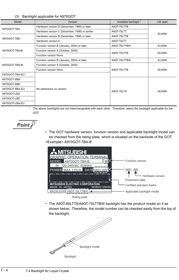
7.4 Backlight for Liquid Crystal 7 - 3
7.4.1 How to change the backlight for liquid crystal... 7 - 5
8 ERROR CODES AND ERROR MESSAGES 8 - 1 to 8 - 15
8.1 Definition of the Error Codes and Messages Displayed 8 - 1
8.2 Error Code and Error Message List 8 - 2
8.3 Precautions for use of flash PC card 8 - 6
8.4 Precautions for installation of ROM_BIOS 8 - 7
8.5 Troubleshooting in bus connection 8 - 8
8.5.1 Locating error positions ... 8 - 8 8.5.2 Further locating error positions ... 8 - 13 8.5.3 Specific example of troubleshooting ... 8 - 14
8.6 Troubleshooting for monitoring 8 - 15
APPENDICES App - 1 to App - 11
Appendix.1 External Dimensions App - 1
Appendix.2 Depth at the Time of Communication Board/Communication Unit Loading App - 4
Appendix.3 External Dimensions of Bus Connection Cables App - 8
Appendix.4 Specifications of former models App - 10
Appendix.4.1 Performance specifications of the A975GOT-TBA/TBD, A970GOT-TBA/TBD ...App - 10
INDEX Index - 1 to Index - 2
A - 11 ABOUT THE MANUALS
For details of the manuals relevant to this product, refer to the PDF manual stored within the drawing software
used.
A - 12
ABBREVIATIONS AND GENERIC TERMS IN THIS MANUAL
Abbreviations and generic terms used in this manual are described as follows
:
Abbreviations and generic terms Description
GOT
A985GOT-V Generic term of A985GOT-TBA-V and A985GOT-TBD-V
A985GOT Generic term of A985GOT-TBA, A985GOT-TBD and A985GOT-TBA-EU
A975GOT Generic term of A975GOT-TBA-B, A975GOT-TBD-B, A975GOT-TBA, A975GOT-TBD and A975GOT-TBA-EU
A970GOT
Generic term of A970GOT-TBA-B A970GOT-TBD-B, A970GOT-TBA, A970GOT-TBD, A970GOT- SBA, A970GOT-SBD, A970GOT-LBA, A970GOT-LBD, A970GOT-TBA-EU, A970GOT-SBA-EU and A970GOT-LBA-EU
A97 GOT Generic term of A975GOT and A970GOT
A960GOT Generic term of A960GOT-EBA, A960GOT-EBD and A960GOT-EBA-EU Communica-
tion board
Bus connection board Generic term of A9GT-QBUSS, A9GT-QBUS2S, A9GT-BUSS and A9GT-BUS2S Serial communica-
tion board Generic term of A9GT-RS4, A9GT-RS2 and A9GT-RS2T
Communica- tion unit
Bus connection unit Generic term of A9GT-BUSSU and A9GT-BUS2SU
Data link unit Generic term of A7GT-J71AP23, A7GT-J71AR23 and A7GT-J71AT23B
Network unit Generic term of A9GT-QJ71LP23, A9GT-QJ71BR13, A7GT-J71LP23 and A7GT-J71BR13 CC-Link communica-
tion unit Generic term of A8GT-J61BT13 and A8GT-J61BT15 Ethernet communica-
tion unit Abbreviation of A9GT-J71E71-T
Option unit
External I/O interface
unit Abbreviation of A9GT-70KBF type external I/O interface unit Video/RGB hybrid
interface unit Abbreviation of A9GT-80V4R1 type Video/RGB hybrid interface unit Video input interface
unit Abbreviation of A9GT-80V4 type Video input interface unit RGB input interface
unit Abbreviation of A9GT-80R1 type RGB input interface unit
Option
Backlight Abbreviation of A9GT-80LTT, A9GT-70LTTBW, A9GT-70LTTB, A9GT-70LTT and A9GT-70LTS type backlights
Debug stand Abbreviation of A9GT-80STAND and A9GT-70STAND type debug stand
Memory board Abbreviation of A9GT-FNB, A9GT-FNB1M, A9GT-FNB2M, A9GT-FNB4M, A9GT-FNB8M, A9GT- QFNB, A9GT-QFNB4M, A9GT-QFNB8M type option function memory board
Ten-key Panel Abbreviation of A8GT-TK ten-key Panel
A7GT-CNB Abbreviation of A7GT-CNB bus connector conversion box A9GT-QCNB Abbreviation of A9GT-QCNB bus connector conversion box
Protection sheet Abbreviation of A9GT-80PSC, A9GT-70PSC and A9GT-60PSC type transparent protection sheets Attachment Generic term of A77GT-96ATT/A87GT-96ATT/A87GT-97ATT attachments
PC card (memory
card) Abbreviation of PC card with PCMCIA Ver.2.1
Flash PC card Generic term of A9GTMEM-10MF, A9GTMEM-20MF and A9GTMEM-40MF Compact flash PC
card Compact flash PC card compliant with Compact FlashTM
A - 13
Software
GT Works Version5 Abbreviation of SW5D5C-GTWORKS-E(-V) software GT Designer Version5 Abbreviation of SW5D5C-GOTR-PACKE(V) software GT Works2 Version1 Abbreviation of SW1D5C-GTWK2-E software GT Designer2
Version1 Abbreviation of SW1D5C-GTD2-E software
GT Designer Abbreviation of image creation software GT Designer for GOT900 GT Designer2 Abbreviation of image creation software GT Designer2 for GOT900 GT Simulator Abbreviation of GT Simulator screen simulator GOT900
GT Simulator2 Abbreviation of GT Simulator2 screen simulator GOT900
GT Converter Abbreviation of data conversion software GT Converter for GOT900 GT Debugger Abbreviation of debugging software GT Debugger
GT Manager Abbreviation of GT Manager data editing software for GOT900 GT SoftGOT Abbreviation of GT SoftGOT monitoring software
GT SoftGOT2 Abbreviation of GT SoftGOT2 monitoring software
GX Developer Generic term of SW D5C-GPPW-E/SW D5F-GPPW-E software packages
GX Simulator Generic term of SW D5C-LLT-E ladder logic test tool function software package (SW5D5C-LLT-E or later)
CPU
QCPU (Q Mode) Generic term of Q00JCPU, Q00CPU, Q01CPU,Q02CPU, Q02HCPU, Q06HCPU, Q12HCPU, Q25HCPU, Q12PHCPU and Q25PHCPU CPU
QCPU (A Mode) Generic term of Q02CPU-A, Q02HCPU-A and Q06HCPU-A CPU QCPU Generic term of QCPU (Q Mode) and QCPU (A Mode)
QnACPU Type Generic term of Q2ACPU, Q2ACPU-S1, Q2AHCPU, Q2AHCPU-S1, Q3ACPU, Q4ACPU and Q4ARCPU CPU
QnASCPU Type Generic term of Q2ASCPU, Q2ASCPU-S1, Q2ASHCPU and Q2ASHCPU-S1 CPU QnACPU Generic term of QnACPU Type and QnASCPU Type
AnUCPU Generic term of A2UCPU, A2UCPU-S1, A3UCPU and A4UCPU CPU AnACPU Generic term of A2ACPU, A2ACPU-S1 and A3ACPU CPU
AnNCPU Generic term of A1NCPU, A2NCPU, A2NCPU-S1 and A3NCPU CPU AnCPU Type Generic term of AnUCPU, AnACPU and AnNCPU CPU
AnUS(H)CPU Generic term of A2USCPU, A2USCPU-S1 and A2USHCPU-S1 CPU
AnS(H)CPU Generic term of A1SCPU, A1SCPUC24-R2, A2SCPU, A2SCPU-S1, A1SHCPU, A2SHCPU and A2SHCPU-S1 CPU
A1SJ(H)CPU Generic term of A1SJCPU, A1SJCPU-S3 and A1SJHCPU CPU AnSCPU Type Generic term of A2US(H)CPU, AnS(H)CPU and A1SJ(H)CPU CPU
ACPU Generic term of AnCPU Type, AnSCPU Type, A1FXCPU, A0J2HCPU, A2CCPU, A2CCPU24 and A2CJCPU CPU
FXCPU Generic term of FX0 series, FX0N series, FX0S series, FX1 series, FX1N series, FX1S series, FX2 series, FX2C series, FX2N series, FXINS series and FX2NC series CPU
Motion controller CPU
Generic term of A273UCPU, A273UHCPU, A273UHCPU-S3, A373CPU, A373UCPU, A373UCPU-S3, A171SCPU, A171SCPU-S3, A171SCPU-S3N, A171SHCPU, A171SHCPUN, A172SHCPU, A172SHCPUN, A173UHCPU, A173UHCPU-S1 CPU
FA controller Generic term of LM610, LM7600, LM8000 CPU Peripheral
connection module
G4 Abbreviation of AJ65BT-G4-S3
Ethernet module
E71
Generic term of AJ71E71-S3, AJ71E71N-T, AJ71E71N-B2, AJ71E71N-B5, AJ71E71N-B5T, A1SJ71E71-B2-S3, A1SJ71E71-B5-S3, A1SJ71E71N-T, A1SJ71E71N-B2, A1SJ71E71N-B5 and A1SJ71E71N-B5T
QE71
Generic term of AJ71QE71, AJ71QE71-B5, AJ71QE71N-T, AJ71QE71N-B2, AJ71QE71N-B5, AJ71QE71N-B5T, A1SJ71QE71-B2, A1SJ71QE71-B5, A1SJ71QE71N-T, A1SJ71QE71N-B2, A1SJ71QE71N-B5 and A1SJ71QE71N-B5T
Q series-compatible
E71 Generic term of QJ71E71, QJ71E71-B2, QJ71E71-B5, QJ71E71-100
Abbreviations and generic terms Description
A - 14
Other PLC
Omron PLC
Generic term of C200HS, C200H, C200H series(C200HX, C200HG, C200HE), CQM1, C1000H,C2000H,CV500, CV1000, CV2000, CVM1-CPU11, CVM1-CPU21, CS1, CS1D, CJ1M, CPM1, CPM1A, CPM2A, CPM2C CPU, CQM1H
Yaskawa PLC Generic term of GL60S, GL60H, GL70H, GL120, GL130, CP-9200SH, CP-9300MS, MP-920, MP-930, MP-940, CP-9200(H) and PROGIC-8 CPU
SLC500 Series Generic term of SLC500-20, SLC500-30, SLC500-40, SLC5/01 SLC5/02, SLC5/03, SLC5/04 SLC5/05
MicroLogix1000 Series
Generic term of 1761-L10BWA, 1761-L10BWB, 1761-L16AWA, 1761-L16BWA, 1761-L16BWB, 1761-L16BBB, 1761-L32AWA, 1761-L32BWA, 1761-L32BWB, 1761-L32BBB, 1761-L32AAA, 1761-L20AWA-5A, 1761-L20BWA-5A, 1761-L20BWB-5A
MicroLogix1500
Series Abbreviation of 1764-LSP
Allen-Bradley PLC Generic term of SLC 500 Series, MicroLogix1000 Series, MicroLogix1500 Series Sharp PLC Generic term of JW-21CU, JW-22CU, JW-31CUH, JW-32CUH, JW-33CUH, JW-50CUH,
JW-70CUH, JW-100CUH, JW-100CU, Z-512J CPU PROSEC T Series Generic term of T2(PU224 type), T2E, T2N, T3, T3H CPU PROSEC V Series Generic term of S2T and Model3000(S3) CPU
Toshiba PLC Generic term of PROSEC T Series and PROSEC V Series
SIEMENS PLC Generic term of SIMATIC S7-300 Series and SIMATIC S7-400 Series CPU
Large type H series Generic term of H-302(CPU2-03H), H-702(CPU2-07H), H-1002(CPU2-10H), H-2002(CPU2-20H), H-4010(CPU3-40H),.J-300(CPU-03Ha), H-700(CPU-07Ha), H-2000(CPU-20Ha)
H200 to 252 Series Generic term of H-200(CPU-02H, CPE-02H), H-250(CPU21-02H), H-252(CPU22-02H), H-252B(CPU22-02HB), H-252C(CPU22-02HC, CPE22-02HC)
H Series board type Generic term of H-20DR, H-28DR, H-40DR, H-64DR, H-20DT, H-28DT, H-40DT, H-64DT, HL-40DR, HL-64DR
EH-150 Series Generic term of EH-CPU104, EH-CPU208, EH-CPU308, EH-CPU316 HITACHI PLC
(HIDIC H Series) Generic term of large type H series, H-200 to 252 Series H Series board type, EH-150 Series Matsushita Electric
Works PLC
Generic term of FP0-C16CT, FP0-C32CT, FP1-C24C, FP1-C40C, FP2, FP2SH, FP3, FP5, FP10(S), FP10SH, FP-M(C20TC) and FP-M(C32TC)
Others
Memory abbreviation of memory (flash memory) in the GOT
OS Abbreviation of GOT system software
Object Setting data for dynamic image
Personal Computer Personal computer where the corresponding software package is installed Servo amplifier Generic term of the MR-J2S-οA, MR-J2S-οCP and MR-J2M A series MELDAS C6/C64 Generic term of the FCA C6, FCA C64
Abbreviations and generic terms Description
A - 15 PACKING LIST
After unpacking, confirm that the following parts are included.
*1 Affix a caution plate in a conspicuous position such as memory card interface part.
(Affix a caution plate on a communication unit during its use.) The caution plate is included only in the following GOT models.
A97* GOT (except -EU): Hardware version L (Jun., 2001) or later.
A960GOT (except -EU): Hardware version H (Jun., 2001) or later.
*2 Changes with the GOT you purchased.
Product Quantity
GOT main unit 1
Mounting fixture 4
Communication unit secur-
ing fixture 3
Caution plate (seal)*1 1
A975GOT-TBA/TBD(-B), A970GOT-TBA/TBD(-B), A970GOT-SBA/SBD, A970GOT-LBA/LBD, A960GOT-EBA/EBD User's Manual (Hardware) *
2A985GOT-TBA-EU, A975GOT-TBA-EU, A970GOT-TBA-EU,
1A970GOT-SBA-EU, A970GOT-LBA-EU, A960GOT-EBA-EU User's Manual (Hardware) *
2A985GOT-TBA/TBD(-V) User's Manual (Hardware) *
2When affixing a caution plate on the memory card interface
Caution plate Caution plate
When affixing a caution plate on the communication unit
1 - 1
1 OVERVIEW
This user's manual explains the specifications, handling and other information of the GOT-A900 series graphic operation terminal (abbreviated to the GOT).
The GOT can be used as an electronic operator panel which has achieved on its monitor screen the switch operation, lamp indication, data display, message display and other operations which were previously per- formed on an operator panel.
The following GOT types are available.
Type Rough Specifications
Power supply type Display color [Color] Display section Resolution [Dots] Screen size [cm]
A985GOT-TBA- V 100 to 240VAC 256
(During image display: 65536)
TFT color liquid crystal
800 600 31 (12inch)
A985GOT-TBD- V 24VDC
A985GOT-TBA 100 to 240VAC
256
A985GOT-TBD 24VDC
A985GOT-TBA-EU 100 to 240VAC A975GOT-TBA 100 to 240VAC
640 480 26 (10inch)
A975GOT-TBD 24VDC
A975GOT-TBA-B 100 to 240VAC
A975GOT-TBD-B 24VDC
A975GOT-TBA-EU 100 to 240VAC A970GOT-TBA 100 to 240VAC
16
A970GOT-TBD 24VDC
A970GOT-TBA-B 100 to 240VAC
A970GOT-TBD-B 24VDC
A970GOT-TBA-EU 100 to 240VAC A970GOT-SBA 100 to 240VAC
8 D-STN color liquid crystal
A970GOT-SBD 24VDC
A970GOT-SBA-EU 100 to 240VAC A970GOT-LBA 100 to 240VAC
2
(Monochrome) STN monochrome liquid crystal
A970GOT-LBD 24VDC
A970GOT-LBA-EU 100 to 240VAC
A960GOT-EBA 100 to 240VAC 2
(Yellow orange, black)
EL 640 400 23 (9inch)
A960GOT-EBD 24VDC
A960GOT-EBA-EU 100 to 240VAC
1.1 Features 1 - 2
1
OVERVIEW
2
SYSTEM CONFIGURATION
3
PERFORMANCE
4
PART NAMES AND SETTINGS
5
ROUGH PRE-OPER- ATION PROCEDURE
6
HANDLING
7
MAINTENANCE AND INSPECTION
8
ERROR CODES AND ERROR MESSAGES
1.1 Features
(1) Compact display device in pursuit of mounting, external dimensions and thinness
With the display screen size identical to that of the conventional type, the external dimensions and depth are substantially reduced to achieve a compact size and thin design.
The GOT is designed to connect cables at its bottom to ensure that extra space is not needed for the connectors and bending of the cables when the GOT is mounted on a control panel or the like.
(2) User-friendly multimedia display device
Clear, high-grade display has been achieved by 256-color representation. (A975GOT, A985GOT (-V) only)
Ear-appealing information transmission has also been achieved by supporting speech output using the Windows WAV file.
(3) Fast data transfer of OS and screen data by memory card
The PC card for OS and screen data can be created easily on a personal computer. By loading the created card into the GOT, you can exchange the OS and screen data rapidly. (RS-232C data transfer can also be made as conventionally.)
A870GOT
A970GOT A870GOT
A970GOT
Line 1 stopped!
Commercially available PC card (Compliant with PCMCIA Ver.2.1)
1 - 3 1.1 Features
(4) Compatible with a wide variety of connection forms
The GOT is compatible with various connection forms such as the MELSEC and computer link connections, including the bus connection which permits fast communication. You can choose the connection form matching the system.
(5) Heavy-duty body usable in rigorous environment and operation
The display section of the GOT complies with the IP65f, IP67f and NEMA4 Waterproof, Dustproof Standard and is usable in a wide range of environment.
(6) Maintenance function further enhanced in affinity with PLC
• Supporting the factor search mode which searches for the contact of a failure factor at the device search time in the ladder monitoring function, the GOT has shortened the failure factor analysis time.
• Upgraded alarm history function
The GOT can support the failure occurrence counting function, cumulative failure time totalizing function and history printing function, and start ladder monitoring with the corresponding device searched with a single keystroke at the failure detail display time.
(7) Improvement of safety by upgraded security function
• Supporting the operation protective function using up to 16 levels of passwords, the GOT can hide the display or disable input operation according to the password level. You can achieve hidden screens and hidden operations and easily change the display data per GOT used.
• You can specify the time delay function (ON delay/OFF delay) of the touch switches, double- pushing switches and interlock conditions to reduce malfunctions due to wrong key pushing.
(8) Energy saving mode using human sensor (A985GOT(-V) only)
• The human sensor detects operators in the sensor detection area and turns the backlight ON/
OFF automatically.
The backlight can be turned off automatically if no operator motions are not detected for a given
period of time. (This time can be set by the user.)
1.2 Requirements to meet EMC Directive
1.2.1 EMC Directive 1 - 4
1
OVERVIEW
2
SYSTEM CONFIGURATION
3
PERFORMANCE
4
PART NAMES AND SETTINGS
5
ROUGH PRE-OPER- ATION PROCEDURE
6
HANDLING
7
MAINTENANCE AND INSPECTION
8
ERROR CODES AND ERROR MESSAGES
1.2 Requirements to meet EMC Directive
EMC Directives which are among European Directives become forced.
EMC Directives are those which require "any strong electromagnetic force is not output to the external.:
Emission (electromagnetic interference)" and "It is influenced by the electromagnetic wave from the external.: Immunity (electromagnetic sensitivity)".
Items 1.2.1 thru 1.2.3 summarize the precautions to use GOT and configure the mechanical unit in order to match the EMC directives.
Though the data described herein are produced with our best on the basis of the requirement items and standards of the restrictions gathered by Mitsubishi, they do not completely guaranteed that all mechanical unit manufactured according to the data do not always match the above directives. The manufacturer itself which manufactures the mechanical unit must finally judge the method and others to match the EMC directives.
1.2.1 EMC Directive
The standards of the EMC Directive are shown below.
*1 QP: Quasi-peak value, Mean: Average value
*2 The GOT is an open type device (device installed to another device) and must be installed in a conductive control panel.
The above test items are conducted in the condition where the GOT is installed on the conductive control panel and combined with the Mitsubishi PLC.
Specification Test item Test details Standard value
EN61000-6-4 : 2001
EN55011 Radiated noise*2
Electromagnetic emissions from the product are mea- sured.
30 M-230 MHz QP:
30 dB V/m (30 m in measurement range) *1 230 M-1000 MHz QP:
37 dB V/m (30 m in measurement range)
EN55011 Conducted noise*2
Electromagnetic emissions from the product to the power line is measured.
150 k-500 kHz QP:
79 dB, Mean: 66 dB*1 500 k-30 MHz QP:
3 dB, Mean: 60 dB
EN61131-2 : 1994/A12 (2000)
EN61000-4-2
Electrostatic immunity*2
Immunity test in which static electricity is applied to the cabinet of the equip- ment.
15kV Aerial discharge
EN61000-4-4 Fast transient burst noise*2
Immunity test in which burst noise is applied to the power line and signal lines.
Power line: 2kV
Digital I/O (24V or higher): 1kV (Digital I/O (24V or less) 250V (Analog I/O, signal lines) 250V EN61000-4-3
Radiated field AM modu- lation*2
Immunity test in which field is irradiated to the product.
10V/m, 26-1000 MHz, 80%AM modulation@1 kHz
EN61000-4-12
Damped oscillatory wave immunity*2
Immunity test in which a damped oscillatory wave is superimposed on the power line.
Power line: 1kV
Digital I/O (24V or higher): 1 kV
1 - 5 1.2 Requirements to meet EMC Directive 1.2.2 Installation inside Control Panel
1.2.2 Installation inside Control Panel
The GOT is an open type device (device installed to another device) and must be installed in a conductive control panel.
It not only assure the safety but also has a large effect to shut down the noise generated from GOT, on the control panel.
(1) Control panel
(a) The control panel must be conductive.
(b) When fixing a top or bottom plate of the control panel with bolts, do not coat the plate and bolt surfaces so that they will come into contact.
And connect the door and box using a thick grounding cable in order to ensure the low impedance under high frequency.
(c) When using an inner plate to ensure electric conductivity with the control panel, do not coat the fixing bolt area of the inner plate and control panel to ensure conductivity in the largest area as possible.
(d) Ground the control panel using a thick grounding cable in order to ensure the low impedance under high frequency.
(e) The diameter of cable holes in the control panel must be 10cm (3.94in.). In order to reduce the chance of radio waves leaking out, ensure that the space between the control panel and its door is small as possible.
Attach some EMI gaskets to fill up the space and suppress the leakage of radio waves.
Our test have been carried out on a panel having the damping characteristics of 37 dB max.
and 30 dB mean (measured by 3m method with 30 to 300 MHz).
(2) Connection of power and ground wires
Ground and power supply wires for the GOT must be connected as described below.
(a) Provide an earthing point near the GOT. Earth the power supply's LG and FG terminals (LG : Line Ground, FG : Frame Ground) with the thickest and shortest wire possible. (The wire length must be 30cm (11.18in.) or shorter.) The LG and FG terminals function is to pass the noise generated in the PLC system to the ground, so an impedance that is as low as possible must be ensured. As the wires are used to relieve the noise, the wire itself carries a large noise content and thus short wiring means that the wire is prevented from acting as an antenna.
Note) A long conductor will become a more efficient antenna at high frequency.
(b) The earth wire led from the earthing point must be twisted with the power supply wires. By
twisting with the earthing wire, noise flowing from the power supply wires can be relieved to the
earthing. However, if a filter is installed on the power supply wires, the wires and the earthing
wire may not need to be twisted.
1.2 Requirements to meet EMC Directive
1.2.3 Noise filter (power supply line filter) 1 - 6
1
OVERVIEW
2
SYSTEM CONFIGURATION
3
PERFORMANCE
4
PART NAMES AND SETTINGS
5
ROUGH PRE-OPER- ATION PROCEDURE
6
HANDLING
7
MAINTENANCE AND INSPECTION
8
ERROR CODES AND ERROR MESSAGES
1.2.3 Noise filter (power supply line filter)
The noise filter (power supply line filter) is a device effective to reduce conducted noise. Except some models, installation of a noise filter onto the power supply lines is not necessary. However conducted noise can be reduced if it is installed. (The noise filter is generally effective for reducing conducted noise in the band of 10MHz or less.) Usage of the following filters is recommended.
The precautions required when installing a noise filter are described below.
(1) Do not install the input and output cables of the noise filter together to prevent the output side noise will be inducted into the input side cable where noise has been eliminated by the noise filer
(2) Connect the noise filter's ground terminal to the control panel with the shortest cable as possible (approx. 10cm (3.94in) or less).
Model name FN343-3/01 FN660-6/06 ZHC2203-11
Manufacturer SCHAFFNER SCHAFFNER TDK
Rated current 3A 6A 3A
Rated voltage 250V
a) Installing the input and output cables together will
cause noise induction. b) Cable from the output cable.
Filter
Induction
Output side (device side) Input side (power supply side)
Filter
Output side (device side) Input side
(power supply side)
1 - 7 1.3 Requirements for compliance with the Low Voltage Directive 1.3.1 Standard subject to for GOT
1.3 Requirements for compliance with the Low Voltage Directive
The Low Voltage Directive is mandatory within Europe, effective 1st January 1997.
The Low Voltage Directive requires each device which operates with power supply ranging from 50VAC to 1000V and 75VDC to 1500V to satisfy necessary safety items.
In the Sections from 1.3.1 to 1.3.5, cautions on installation and wiring of the GOT to conform to the Low Voltage Directive requires are described.
We have put the maximum effort to develop this material based on the requirements and standards of the Directive that we have collected. However, compatibility of the devices which are fabricated according to the contents of this manual to the above Directive is not guaranteed. Each manufacturer who fabricates such device should make the final judgement about the application method of the Low Voltage Directive and the product compatibility.
1.3.1 Standard subject to for GOT
The standard subject to for GOT is EN61010-1 safety of devices used in measurement rooms, control rooms, or laboratories.
1.3.2 Power supply
The insulation specification of the GOT was designed assuming installation category II. Be sure to use the installation category II power supply to the GOT.
The installation category indicates the durability level against surge voltage generated by lightning strike.
Category I has the lowest durability; category IV has the highest durability.
Category II indicates a power supply whose voltage has been reduced by two or more levels of isolating transformers from the public power distribution.
Installation Category
Category I Category II
Category III Category IV
1.3 Requirements for compliance with the Low Voltage Directive
1.3.3 Control Panel 1 - 8
1
OVERVIEW
2
SYSTEM CONFIGURATION
3
PERFORMANCE
4
PART NAMES AND SETTINGS
5
ROUGH PRE-OPER- ATION PROCEDURE
6
HANDLING
7
MAINTENANCE AND INSPECTION
8
ERROR CODES AND ERROR MESSAGES
1.3.3 Control Panel
Because the GOT is open type equipment (device designed to be stored within another device), be sure to use it only when installed in a control panel.
(1) Shock protection
In order to prevent those who are unfamiliar with power facility, e.g., an operator, from getting a shock, make sure to take the following measures on the control panel.
(a) Store the GOT within the control panel locked, and allow only those who are familiar with power facility to unlock the panel.
(b) Build the structure in order that the power supply will be shut off when the control panel is opened.
(2) Dustproof and waterproof features
The control panel also provides protection from dust, water and ether substances. Insufficient ingression protection may lower the insulation withstand voltage, resulting in insulation destruction.
The insulation in the GOT is designed to cope with the pollution level 2, so use in an environment with pollution level 2 or higher.
1.3.4 Grounding
There are two kinds of grounding terminals as shown below. Both terminals must be grounded.
Be sure to ground the grounding for the safety reasons and EMC Directives.
Pollution level 1 : An environment where the air is dry and conductive dust does not exist.
Pollution level 2 : An environment where conductive dust does not usually exist, but occasional temporary conductivity occurs due to the accumulated dust.
Generally, this is the level for inside the control panel equivalent a control room or on the floor of a typical factory.
Pollution level 3 : An environment where conductive dust exits and conductivity may be generated due to the accumulated dust.
An environment for a typical factory floor.
Pollution level 4 : Continuous conductivity may occur due to rain, snow, etc.
An outdoor environment.
Protective grounding : Maintains the safety of the GOT and improves the noise resistance.
Functional grounding : Improves the noise resistance.
1 - 9 1.3 Requirements for compliance with the Low Voltage Directive 1.3.5 External wiring
1.3.5 External wiring
(1) External devices
When a device with a hazardous voltage circuit is externally connected to the PLC, select a model which complies with the Low Voltage Directive's requirements for isolation between the primary and secondary circuits.
(2) Insulation requirements
Dielectric withstand voltages are shown in the following table.
Reinforced Insulation Withstand Voltage (Installation Category II, source : IEC664)
Rated voltage of hazardous voltage area Surge withstand voltage (1.2/50 µs)
150 VAC or below 2500V
300 VAC or below 4000V
2.1 Overall Configuration 2 - 1
1
OVERVIEW
2
SYSTEM CONFIGURATION
3
PERFORMANCE
4
PART NAMES AND SETTINGS
5
ROUGH PRE-OPER- ATION PROCEDURE
6
HANDLING
7
MAINTENANCE AND INSPECTION
8
ERROR CODES AND ERROR MESSAGES
2 SYSTEM CONFIGURATION
This chapter explains the system configuration of the GOT.
2.1 Overall Configuration
The overall configuration of the GOT is shown below.
*1 For details of the system configuration, refer to the [GOT-A900 Series User's Manual (Connection System Manual)].
*2 Only the A985GOT may be connected to the CRT. (A985GOT-V can not be used.) PC card (Memory card) Memory board
e.g. A9GT-FNB
Protective sheet
e.g. A9GT-70PSC
Debug stand
e.g. A9GT-70STAND
Personal computer
Commercially available GOT
A985GOT(-V)/A97 GOT/A960GOT
Bar code reader Speech output device
Commercially available (Compatible with stereo
mini-jack) Communication unit
e.g. A7GT-J71AP23 Commercially available Based on JEIDA Ver4.2 (Based on PCMCIA2.1)
Printer
Commercially available Window compatible printer
CRT
Commercially available e.g. A9GT-70KBF
e.g. A9GT-BUSS
Option unit 1
1
Communication board 1
1 2
1
Commercially available
2 - 2 2.2 Component List
2.2 Component List
Component Type Description
A985GOT-V A985GOT-TBA-V 31cm (12inch), 256 color display, TFT color liquid crystal, 100 to 240VAC, Video/RGB display supports A985GOT-TBD-V 31cm (12inch), 256 color display, TFT color liquid crystal, 24VDC, Video/RGB display supports
A985GOT
A985GOT-TBA 31cm (12inch), 256 color display, TFT color liquid crystal, 100 to 240VAC, built-in CRT interface A985GOT-TBD 31cm (12inch), 256 color display, TFT color liquid crystal, 24VDC, built-in CRT interface
A985GOT-TBA-EU 31cm (12inch), 256 color display, TFT color liquid crystal, 100 to 240VAC, built-in CRT interface, EMC Directive and Low Voltage Directive compliant product
A975GOT
A975GOT-TBA 26cm (10inch), 256 color display, TFT color liquid crystal, 100 to 240VAC A975GOT-TBD 26cm (10inch), 256 color display, TFT color liquid crystal, 24VDC A975GOT-TBA-B 26cm (10inch), 256 color display, TFT color liquid crystal, 100 to 240VAC A975GOT-TBD-B 26cm (10inch), 256 color display, TFT color liquid crystal, 24VDC A975GOT-TBA-EU 26cm (10inch), 256 color display, TFT color liquid crystal, 100 to 240VAC,
EMC Directive and Low Voltage Directive compliant product
A970GOT
A970GOT-TBA 26cm (10inch), 16 color display, TFT color liquid crystal, 100 to 240VAC A970GOT-TBD 26cm (10inch), 16 color display, TFT color liquid crystal, 24VDC A970GOT-TBA-B 26cm (10inch), 16 color display, TFT color liquid crystal, 100 to 240VAC A970GOT-TBD-B 26cm (10inch), 16 color display, TFT color liquid crystal, 24VDC A970GOT-TBA-EU 26cm (10inch), 16 color display, TFT color liquid crystal, 100 to 240VAC,
EMC Directive and Low Voltage Directive compliant product
A970GOT-SBA 26cm (10inch), 8 color display, D-STN color liquid crystal, 100 to 240VAC A970GOT-SBD 26cm (10inch), 8 color display, D-STN color liquid crystal, 24VDC A970GOT-SBA-EU 26cm (10inch), 8 color display, D-STN color liquid crystal, 100 to 240VAC,
EMC Directive and Low Voltage Directive compliant product A970GOT-LBA 26cm (10inch), STN monochrome liquid crystal, 100 to 240VAC A970GOT-LBD 26cm (10inch), STN monochrome liquid crystal, 24VDC A970GOT-LBA-EU 26cm (10inch), STN monochrome liquid crystal, 100 to 240VAC,
EMC Directive and Low Voltage Directive compliant product
A960GOT
A960GOT-EBA 23cm (9inch), 2 color display, EL, 100 to 240VAC A960GOT-EBD 23cm (9inch), 2 color display, EL, 24VDC A960GOT-EBA-EU 23cm (9inch), 2 color display, EL, 100 to 240VAC,
EMC Directive and Low Voltage Directive compliant product Bus connection
board
A9GT-QBUSS For bus connection, small connector type (For QCPU (Q mode)) A9GT-BUSS
For bus connection, small connector type (For A/QnA/Motion controller CPU) Bus connection
unit A9GT-BUSSU
Multidrop bus connection board
A9GT-QBUS2S For multidrop bus connection, small connector type (For QCPU (Q mode)) A9GT-BUS2S
For multidrop bus connection, small connector type (For A/QnA/Motion controller CPU) Multidrop bus
connection unit A9GT-BUS2SU
Serial communication board
A9GT-RS4 For Direct connection to CPU/Computer link connection/Microcomputer connection and RS-422 connection (Without clock function)
A9GT-RS2 For Direct connection to CPU/Computer link connection/Microcomputer connection and RS-232C connection (Without clock function)
A9GT-RS2T For Direct connection to CPU/Computer link connection/Microcomputer connection and RS-232C connection (Incorporating clock function)
Data link unit
A7GT-J71AP23 For MELSECNET(II) optical link connection, for use as local station A7GT-J71AR23 For MELSECNET(II) coaxial link connection, for use as local station A7GT-J71AT23B For MELSECNET/B connection, for use as local station
Network unit
A9GT-QJ71LP23 For MELSECNET/10 optical loop network connection, for use as normal station*1 A9GT-QJ71BR13 For MELSECNET/10 coaxial bus network connection, for use as normal station*1 A7GT-J71LP23 For MELSECNET/10 optical loop network connection, for use as normal station*1 A7GT-J71BR13 For MELSECNET/10 coaxial bus network connection, for use as normal station*1 CC-Link
communication unit
A8GT-J61BT13 For CC-Link connection, for use as intelligent device station A8GT-J61BT15 For CC-Link connection, for use as remote device station Ethernet
communication unit
A9GT-J71E71-T For Ethernet connection
Protective sheet
A9GT-80PSC Transparent protective sheet for A985GOT(-V), MITSUBISHI logotype can be removed.
A9GT-70PSC Transparent protective sheet for A975/970GOT, MITSUBISHI logotype can be removed.
A9GT-60PSC Transparent protective sheet for A960GOT, MITSUBISHI logotype can be removed.
2.2 Component List 2 - 3
1
OVERVIEW
2
SYSTEM CONFIGURATION
3
PERFORMANCE
4
PART NAMES AND SETTINGS
5
ROUGH PRE-OPER- ATION PROCEDURE
6
HANDLING
7
MAINTENANCE AND INSPECTION
8
ERROR CODES AND ERROR MESSAGES Backlight
A9GT-80LLT
Backlight for A985GOT(-V)*2 A9GT-80LTTA
A9GT-70LTT
Backlight for A975/970GOT TFT color liquid crystal type*2 A9GT-70LTTB
A9GT-70LTTBW
A9GT-70LTS Backlight for A970GOT D-STN color/monochrome liquid crystal type Debug stand A9GT-80STAND Debug stand for A985GOT(-V)
A9GT-70STAND Debug stand for A975/970/960GOT
Attachment
A77GT-96ATT Attachment used for replacement from A77GOT to A960GOT A87GT-96ATT Attachment used for replacement from A870GOT to A960GOT A87GT-97ATT Attachment used for replacement from A870GOT to A975/970GOT External I/O
interface unit A9GT-70KBF For external I/O equipment connection Video/RGB
hybrid interface unit
A9GT-80V4R1 For video camera/personal computer connection
Video input
interface unit A9GT-80V4 For video camera connection RGB input
interface unit A9GT-80R1 For personal computer connection Numeric
keypad panel A8GT-TK Data entry Numeric Keypad Panel
Memory board
A9GT-FNB Exclusively used for optional OS storage (MELSEC-A/FX Ladder monitor-compatible) A9GT-FNB2M For optional function OS storage + built-in memory extension, 2M bytes
(MELSEC-A/FX Ladder monitor-compatible)
A9GT-FNB4M For optional function OS storage + built-in memory extension, 4M bytes (MELSEC-A/FX Ladder monitor-compatible)
A9GT-FNB8M For optional function OS storage + built-in memory extension, 8M bytes (MELSEC-A/FX Ladder monitor-compatible)
A9GT-QFNB Exclusively used for optional OS storage (MELSEC-Q/QnA/A/FX Ladder monitor-compatible) A9GT-QFNB4M For optional function OS storage + built-in memory extension, 4M bytes
(MELSEC-Q/QnA/A/FX Ladder monitor-compatible)
A9GT-QFNB8M For optional function OS storage + built-in memory extension, 8M bytes (MELSEC-Q/QnA/A/FX Ladder monitor-compatible)
PC card/
memory card
— Commercially available SRAM type PC card (based on JEIDA
Ver4.2 (based on PCMCIA2.1)) *3 Refer to the relevant document.
— Commercially available flash PC card (based on Compact FlashTM) (* Compact FlashTM is a trademark of Sun Disk)
A9GTMEM-10MF For GOT, Memory 16M bytes, (hardware version D or later) flash PC card, formatted*4 A9GTMEM-20MF For GOT, Memory 32M bytes, (hardware version D or later) flash PC card, formatted*4 A9GTMEM-40MF For GOT, Memory 128M bytes, (hardware version P or later) flash PC card, formatted*4
CRT display
RD15M II NEC-MITSUBISHI ELECTRIC VISUAL SYSTEMS CORPORA- TION make, 15inch, 1280 1024dots
*5 Introduced products RD17MX NEC-MITSUBISHI ELECTRIC VISUAL SYSTEMS CORPORA-
TION make, 17inch, 1280 1024dots
RDF19X NEC-MITSUBISHI ELECTRIC VISUAL SYSTEMS CORPORA- TION make, 19inch, 1600 1200dots
RD19NF NEC-MITSUBISHI ELECTRIC VISUAL SYSTEMS CORPORA- TION make, 19inch, 1600 1200dots
TFT display
RDT150S NEC-MITSUBISHI ELECTRIC VISUAL SYSTEMS CORPORA- TION make, 15inch, 1280 768dots
RDT180S NEC-MITSUBISHI ELECTRIC VISUAL SYSTEMS CORPORA- TION make, 18.1inch, 1280 1024dots
Bar code reader — Commercially available bar code reader *3 Refer to the relevant document.
Printer — Printer compliant with ESC/P24-J84 (ESC/P command compatible) *6 Hewlett Packard printers (PLC command compatible)
Speech output
device — Stereo mini-jack compatible speaker (built-in amplifier) Bus extension
connector box A9GT-QCNB Used for connection of the QCPU (Q mode) long-distance bus Bus connector
conversion box A7GT-CNB For conversion from large type connector to small type connector (Used for long-distance bus connection)
Component Type Description
2 - 4 2.2 Component List
Bus connectioncable QCPU (Q mode)
QC06B Cable length 0.6m
For connection between Q base unit and GOT
For connection between GOT and GOT
QC12B Cable length 1.2m
QC30B Cable length 3.0m
QC50B Cable length 5.0m
QC100B Cable length 10.0m
A9GT-QC150BS Cable length 15.0m For connection between Q base unit and
GOT
For connection between GOT and GOT
*These cable are Mitsubishi Electric sys- tem Service Co., Ltd. products.
A9GT-QC200BS Cable length 20.0m A9GT-QC250BS Cable length 25.0m A9GT-QC300BS Cable length 30.0m A9GT-QC350BS Cable length 35.0m
Bus connection cable
AC06B Cable length 0.6m
For connection between large type base unit and A7GT-CNB
AC12B Cable length 1.2m
AC30B Cable length 3.0m
AC50B Cable length 5.0m
AC12B-R Right angle, cable length 1.2m AC30B-R Right angle, cable length 3.0m AC50B-R Right angle, cable length 5.0m
A1SC07B Cable length 0.7m For connection between small type base
unit and GOT
For connection between GOT and GOT A1SC12B Cable length 1.2m
A1SC30B Cable length 3.0m A1SC50B Cable length 5.0m A1SC05NB Cable length 0.5m
For connection between small type base unit and A7GT-CNB
A1SC07NB Cable length 0.7m A1SC30NB Cable length 3.0m A1SC50NB Cable length 5.0m
A8GT-C12NB Cable length 1.2m For connection between large type base
unit and GOT A8GT-C30NB Cable length 3.0m
A8GT-C50NB Cable length 5.0m A8GT-C100EXSS Cable length 10.0m
For connection between small type base unit/A7GT-CNB and GOT
A8GT-C200EXSS Cable length 20.0m A8GT-C300EXSS Cable length 30.0m
A8GT-C100BS Cable length 10.0m For long-distance connection between
A8GT-C200BS Cable length 20.0m GOTs A8GT-C300BS Cable length 30.0m
A370C12B Cable length 1.2m For connection between multi-axis con-
trol and GOT A370C25B Cable length 2.5m
A9GT-J2C10B Cable length 1.0m For connection between A0J2HCPU and
GOT
RS-422 cable
AC30R4-25P Cable length 3m (D-sub 25-pin at both ends) For connection between GOT and PLC CPU
For connection between GOT and serial communication module
For connection between GOT and FXCPU
AC100R4-25P Cable length 10m (D-sub 25-pin at both ends)
AC300R4-25P Cable length 30m (D-sub 25-pin at both ends)
— For connection between GOT and computer link module *7
RS-232C cable
QC30R2 Cable length 3m For connection between GOT and QCPU
AC30R2-9P Cable length 3m (D-sub 9-pin, D-sub 25-pin) For connection between GOT and computer link module
For connection between GOT and personal computer for data transfer*8 AC30R2-9SS Cable length 3m (D-sub 9-pin at both ends)
AC30R2 Cable length 3m (D-sub 25-pin at both ends) For connection between GOT and personal computer for data transfer (9-pin conversion connector required) AC30N2A Cable length 3m (D-sub 25-pin at both ends)
— For connecting the GOT with the power supply unit of the bar code reader*3
Printer cable*9 AC30PIO-20P Cable length 3m For connection between GOT and printer
CRT cable*9 AC50VG Cable length 5m For connection between GOT and CRT
AC300VG Cable length 30m
GT Designer —
Screen creation software for GOT900 Series
GT Designer2 —
Component Type Description
2.2 Component List 2 - 5
1
OVERVIEW
2
SYSTEM CONFIGURATION
3
PERFORMANCE
4
PART NAMES AND SETTINGS
5
ROUGH PRE-OPER- ATION PROCEDURE
6
HANDLING
7
MAINTENANCE AND INSPECTION
8
ERROR CODES AND ERROR MESSAGES
*1 When using the A9GT-QJ71LP23 or A9GT-QJ71BR13, the device range (QCPU, QnACPU, ACPU) that can be monitored varies with the communication driver installed in the GOT.
When using the A7GT-QJ71LP23 or A7GT-QJ71BR13, only the AnA device range can be monitored.
For details, refer to GOT-A900 series User’s Manual (Connection System Manual).
*2 The applicable backlight varies with the GOT version (hardware version, function version).
For details, refer to Section 7.4.
*3 Relevant documentSome devices have been concluded to be applicable for GOT900 series by Mitsubishi.
For details of the devices, refer to the relevant document "List of valid devices applicable for GOT900 series" (Tech- nical bulletin T10-0028).
Please contact your local Mitsubishi representative for the document, if necessary.
The GOT may not operate correctly if a device other than described in the document is used.
*4 Memory capacity differs according to the hardware versions of flash PC card.
It can be checked on the rated plate of flash card.
*5 Introduced productsProducts which have been verified to have the specifications (standards) connectable to our modules. Use the introduced products in compliance with the specifications (standards) of the products.
*6 The printer of ESC/P raster specifications such as the PM series cannot be connected and used with the GOT.
*7 The RS-422 cable for use between GOT and computer link module should be fabricated by the user with reference to the GOT-A900 Series User's Manual (Connection System Manual).
*8 The RS-232C cable may be modified by the user.
For details of cable specifications, refer to the following manuals.
For GT Designer : GT Works Version /GT Designer Version Reference Manual For GT Designer2: GT Designer2 Version Operating Manual
*9 The printer cable and the CRT cable may be fabricated by the user.
Refer to [Chapter 3] for full information on the specifications needed to fabricate the cable.
2 - 6 2.3 Cautions on use of EMC command-and low voltage command-compliant products 2.3.1 Cautions when using PC card/Flash PC card
2.3 Cautions on use of EMC command-and low voltage command-compliant products
The information of the EMC Directive-compliant models is obtained from MELFANSweb homepage (http://
www.nagoya.melco.co.jp/english/).
2.3.1 Cautions when using PC card/Flash PC card
Some GOT models may be incompliant with the EMC Directive when a PC card or flash PC card is used.
The following table shows if they will be compliant with the EMC Directive or not for each PC card type.
: Compliant with EMC Directive : Incompliant with EMC Directive
*1 This model can work as a flash PC card, although incompliant with the EMC Directive.
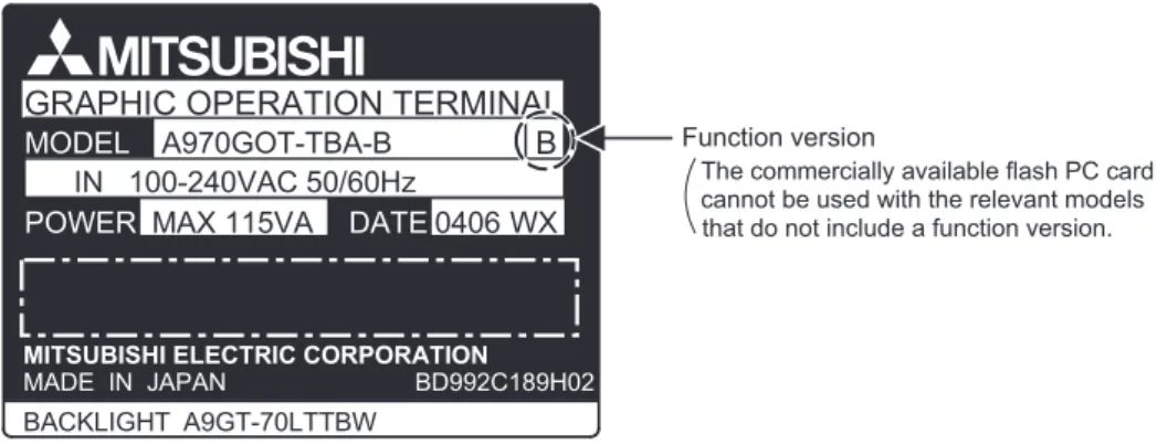
*2 Commercially available flash PC cards are applicable for the GOTs of function version A or later.
The GOT function version is located on the rating plate at the rear of the GOT.
2.3.2 EMC Directive-incompliant communication boards/units
The GOT is incompliant with the EMC Directive when any of the following communication boards/units is used.
GOT model
PC card Commercially available PC card
(SRAM type)
Flash PC card (A9GTMEM-*MF)
Commercially available flash PC card
A985GOT-TBA-EU *1 N/A
A975GOT-TBA-EU *2
A970GOT-TBA-EU *2
A970GOT-SBA-EU *2
A970GOT-LBA-EU *2
A960GOT-EBA-EU *2
Item Type
Bus connection board A9GT-QBUSS, A9GT-QBUS2S
Bus connection unit A9GT-BUSSU, A9GT-BUS2SU
Data link unit A7GT-J71AP23, A7GT-J71AR23, A7GT-J71AT23B
Network unit A9GT-QJ71LP23, A9GT-QJ71BR13, A7GT-J71LP23, A7GT-J71BR13
CC-Link communication unit A8GT-J61BT15
External I/O unit A9GT-70KBF
Function version
MODEL A960GOT-EBA-EU
MADE IN JAPAN LISTED 80M1 IND. CONT. EQ.
MITSUBISHI ELECTRIC CORPORATION 0105LR DATE
A
2.3 Cautions on use of EMC command-and low voltage command-compliant products
2.3.3 Connection Method 2 - 7
1
OVERVIEW
2
SYSTEM CONFIGURATION
3
PERFORMANCE
4
PART NAMES AND SETTINGS
5
ROUGH PRE-OPER- ATION PROCEDURE
6
HANDLING
7
MAINTENANCE AND INSPECTION
8
ERROR CODES AND ERROR MESSAGES
2.3.3 Connection Method
Use the following methods to connect with the GOT to ensure compliance with the EMC Directive.
<How to read the table>
The above table shows the GOT hardware version and compatibility date for each connection method.
(The compatibility date for hardware version A is not shown.) Please use the recommended GOT hardware version or later.
indicates the product is incompliant with the EMC Directive.
*1 For details about each connection method, refer to the GOT-A900 Series User’s Manual (Connection System Manual).
Connection method A985GOT- TBA-EU
A975GOT- TBA-EU
A970GOT- TBA-EU
A970GOT- SBA-EU
A970GOT-LBA- EU
A960GOT- EBA-EU
Bus Connection QCPU
QnA/ACPU A A A A A A
CPU direct connection
QCPU
(RS-232C) T(0105) T(0105) E(0105) A L(0105)
QnA/ACPU
(RS-422) A A A A A A
Computer link connection
RS-232C T(0105) T(0105) E(0105) A L(0105)
RS-422 A A A A A
MELSECNET connection
CC-Link connection
Intelligent device T(0105) T(0105) E(0105) A L(0105)
Remote device station
Ethernet connection Y(0203) Y(0203) M(0203) E(0203) Q(0203)
Microcomputer
connection RS-232C T(0105) T(0105) E(0105) A L(0105)
Other PLC connection
RS-232C T(0105) T(0105) E(0105) A L(0105)
RS-422 A A A A A
E(0105)
Hardware version
(0105) Month
Year (Last 2 digits of A.D. year) Compatibility
date