Chapter 4 Implementation
In this chapter, we will discuss the implementation of DIVINE. In Section 4.1, we describe the development tool of DIVINE. In Section 4.2, we discuss the system structure of DIVINE.
4.1 Development tool
This system can be divided into two parts: one is the debugger and the other is the visualization subsystem. The debugger is written in Java and is constructed by Borland JBuilder environment. In order to include the SDK (Software Development Kit) of data glove that is provided by the hardware product, the visualization subsystem is written in C and is constructed by Microsoft Visual C++ environment.
4.2 System structure
The debugger provides a window-based user interface for users to debug a program. Now, the debugger is designed for Java program and is built on top of JPDA (Java Platform Debugger Architecture). Users can load a Java program and set the breakpoint at a line of the source code. When users enter a variable name such as a reference and press the button marked “VISUALIZE,” the visualization subsystem will be executed. The visualization subsystem detects the data glove and tries to build a socket connection with the debugger. If the data glove is already connected and the visualization subsystem successfully builds the socket connection, the visualization subsystem will create a window to display 3D objects. After successfully creating the
window, it will wait for the information sent from the debugger. The debugger gathers the debugging information from JPDA and sends the information to the visualization subsystem in a specific format. The details of this specific format will be discussed in Section 4.2.1. The visualization subsystem receives the debugging information with the specific format, parses it, and displays it in the 3D graphic environment in a default display method. The details of the default display method will be discussed in Section 4.2.2.
In the 3D graphic environment, users can interact with the visualization subsystem by using a data glove and keyboard. Through these interactions, the visualization subsystem communicates with the debugger to replace the function of entering commands manually. The details of communication between the visualization subsystem and the debugger will be discussed in Section 4.2.3. The system structure is shown in Figure 30.
4.2.1 Interchange data format between the visualization subsystem and the Figure 30 – The structure of DIVINE.
debugger
In this section, we describe the data format for the visualization subsystem and the debugger to communicate with. In Java, there are many primitive data type such as Boolean, char, string, and etc. There is no pointer in Java. Each object is referred by a reference.
There are two kinds of information that we are interested in for debugging. One is the data structure type, and the other is the variable content. For this thesis, we design a format to communicate the above information. In this format there are six fields including variable type, variable id, degree, length, type and context that are separated by the space.
1. Variable type: The field specifies the data structure type of this variable.
2. Variable id: The field specifies the unique number of this variable given by debugger to identify the variable.
3. Degree: The field is an optional field. It is designed for array and object data structure. If there is an array variable, it specifies the dimension of the array data structure. If there is an object variable, it specifies the sum of total fields of the object data structure.
4. Length: The field is an optional field. It is designed for array data structure. It specifies the size of the array data structure.
5. Type: If the variable is a simple data structure, it specifies the name of variable.
Else if the data structure is an array or object data structure. It specifies the contained data fields in the data structure and the name of variable. The name of variable will be marked between “[” and “]”. The format of the contain data fields follows this format, too.
6. Context: The field specifies the content of the variable. The content of a string data structure will be marked between “‘” and “’”.
For example: (The id is an arbitrary and unique number.)
If there is a boolean variable (bool A = true), the format will be represented as
“boolean 1 type [A] context true”.
If there is a float variable (float num = 12.45), the format will be represented as
“numeric 77 type [num] context 12.45”.
If there is a string variable (string sentence = “This is a book”), the format will be represented as “string 22 type [sentence] context ‘This is a book’”.
If there is an one-dimensional array variable (int A[3]), the format will be represented as “array 11 degree 1 length 3 type numeric [A] context 9 8 7”.
If there is a two-dimensional array variable (int B[3][2]), the format will be represented as “array 7 degree 2 length 3 2 type numeric [B] context 1 2 3 4 5 6”.
If there is an object variable (struct A {string name; int id; A next; } ), the format will be represented as “object 9 degree 3 type string numeric link [name, id, next]
context ‘aaaaa’ 1 2“.
Above format is designed for communication between the debugger and the visualization subsystem. The purpose of the format is used as meta-format between the visualization subsystem and the debugger, so that our visualization subsystem can use other debugger as well. Now the debugger is designed for debugging Java programs. If we want to extend our system to debug C programs, all we have to do is writing a new debugger for C and sending the information in this format to the visualization subsystem through the socket. Thus, the visualization subsystem still can parse it and display it in the 3D graphic environment. We need not modify the visualization subsystem at all.
4.2.2 Default display method
There are some tools that can automatically draw data structure, such as dot that
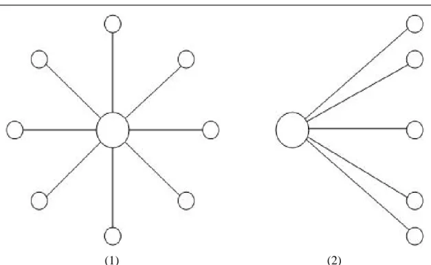
can draw the layout of graph properly [14]. For example, the algorithm of dot can route lines between graphic nodes without crossing another graphic nodes. It contains a complex algorithm to place the nodes and lines beautifully [15]. On the contrary, DIVINE is a completely manual system. DIVINE places the nodes and links in a default display method. It ignores the collision of nodes and crossing lines. If users do not like the visualization layout, users can drag the objects and create a new layout of their own. The default display method displays the data structure in a radial fashion as Figure 31.
Because those objects are drawn in a 3D graphic environment, our system puts the link into the negative z-axis. The new coordinate calculates as follow:
Radius is the radius of the radial fashion.
No is the order of the links.
Count is the number of total links in this node.
(1) (2)
Figure 31 – (1) The default view - Locate at a position with positive z-axis and face towards to negative z-axis
(2) The default view - Locate at a position with positive x-axis and face towards to negative x-axis
new_link.x = node.x + radius * sin(2*π*no/count));
new_link.y = node.y + radius * cos(2*π*no/count));
new_link.z = node.z - 5.0f;
4.2.3 Communication between two parts
The communication between the debugger and the visualization subsystem is designed to replace the function of entering commands manually. The communication makes it possible to integrate the debugger tool and the visualization tool. About the information sending between two parts, there are two solutions to send the information. One solution is sending all of the information at the first time. After sending all of the information, the debugger can be closed. But a linked-list variable may be very large. It will cost a lot of time to send the whole linked-list variable at the first time. Users may not be interested in all information of the whole linked-list data structure. Most communication may be unnecessary. The other solution is sending the information of the variable only when the visualization subsystem requires it. At the first time, the debugger actively sends the head of the linked-list information to the visualization subsystem. After sending the head of the linked-list information, the debugger waits passively. It will keep listening the request command sent from the visualization subsystem. If the debugger receives a request command, it only sends the requested information to the visualization subsystem. We adopt the second solution.
When users want to terminate the visualization, users can press the “Esc” key.
When pressing the “Esc” key, the visualization subsystem sends an “END” command to the debugger. And then closes the connection with the debugger. Finally, terminate the visualization subsystem.