A Simple Dynamic Overmodulation Strategy for Fast Torque Control in DTC of Induction Machine with Constant Switching Frequency Controller
A. Jidin, M.F.M. Basar
Member, IEEE
Universiti Teknikal Malaysia Melaka Locked Bag 1752, 76109 Durian
Tunggal, Malacca, Malaysia [email protected]
N.R.N. Idris, A.H.M. Yatim
Senior Member, IEEE Universiti Teknologi Malaysia
81310 UTM Johore, Malaysia [email protected]
T. Sutikno
Member, IEEE Universitas Ahmad Dahlan
Jln. Prof. Soepomo Janturan, Yogyakarta, Indonesia
Abstract -- This paper presents a simple dynamic overmodulation method to obtain a quick dynamic torque response in Direct Torque Control with constant switching frequency (will be referred as DTC-CSF) induction machines. A fast dynamic torque control can be achieved by applying a voltage vector that produces the largest tangential flux component during the transient condition. To perform this, the flux error status produced from the flux hysteresis comparator is modified before it is being fed to the look-up table, during dynamic condition. The effects of different switching and operating condition on dynamic torque performance are presented. The main benefit of the proposed method is its simplicity since only minor modification is made to the basic DTC hysteresis-based structure.
Index Terms-- Electric Vehicle, Induction Motor, Field Weakening and Overmodulation
I. INTRODUCTION
A high performance of dynamic torque control is very important especially in traction and electric vehicle applications. Numerous technical papers had been proposed by researchers to facilitate vector-controlled induction machines to achieve excellent dynamic torque control utilizing dynamic overmodulation method. It is a common practice in high performance induction motor drive systems that the overmodulation mode is implemented using Space Vector Modulation (SVM). Dynamic overmodulation operation was specifically discussed for vector control and DTC drives in several papers [1]-[5].
In the vector control drives utilizing SVM, it is possible to achieve a quick dynamic torque control utilizing inner current loop. Basically, the input modulator of SVM or voltage reference is approximated so that a larger torque producing current component is achieved to produce fast dynamic torque response. In fact, the proper current regulation is extremely important in FOC system. This becomes problematic (i.e. unstable condition of a high bandwidth of current controller) as the motor currents will have lower order harmonics as it operates in overmodulation region [2]. The problem has been tackled using compensated current with PI current controller as proposed in [3]. In so doing, the scheme
eliminates the use of filter which may decrease the bandwidth of current controller and dynamic performance as well.
Alternatively, the Direct Torque Control (DTC)-SVM method is much preferred solution since its control structure is simpler than FOC-SVM, due to the absence of the current controller, frame transformer and a position encoder.
Habetler et al. proposed dynamic overmodulation utilizing in DTC-SVM to achieve fast dynamic torque response [4][5].
However, the approximated voltage reference is not capable to exploit the overmodulation region until six-step operation.
Hence, this scheme does not give the fastest torque control.
Recently, Tripathi et al. proposed dynamic torque control in the overmodulation and field weakening region using DTC- SVM based on stator flux error control [6]. This scheme is able to achieve the fastest torque response in field weakening region with six-step mode. However the structure of the drive system is more complicated than the hysteresis-based structure DTC as proposed by Takahashi.
In DTC-SVM, various methods have been proposed to compute the voltage reference; these include the use of proportional-integral current controller [3], predictive and dead-beat controllers [4][5][6]. For instance, the voltage reference is computed using several complicated equations in real-time [4][5]. Then, the voltage reference, uref is adjusted (due to physical constraint) to create appropriate voltage reference which is the maximum possible voltage located on the hexagonal boundary. These consequently require major modifications which complicate the basic of DTC structure in [7]. Figure 1 shows variations of approximated voltage proposed by previous researchers. For convenience of comparison, these approximated voltages are drawn with the same voltage reference uref.
This paper presents a straightforward dynamic overmodulation strategy which can be incorporated in basic of DTC structure (with decoupled of torque and flux control structure) in [7] and [9]. [9] is proposed to obtain constant switching frequency and torque ripple reduction as well, in order to overcome the major problem produced in [7]. The operation of the dynamic overmodulation is similar with that proposed in [6] such that in selecting only single voltage vector to produce the largest tangential flux component to
PEDS2009
obtain the fastest torque response. However, [6] uses DTC- SVM utilizing predictive stator flux vector control which is complicated and moreover the computation to calculate precise stator flux vector used to define overmodulation mode is problematic. In the proposed dynamic overmodulation, the flux error status produced from the flux hysteresis comparator is modified before it is being fed to the look-up table. In such manner, a fast torque response can be achieved with six-step mode under dynamic operating condition. This paper will also discuss the effects of some operating conditions on the dynamic torque performance in DTC constant switching frequency (DTC-CSF)-based system. It will be shown that, the proposed dynamic overmodulation is also capable of producing a fast torque response in field weakening region with six-step operation.
Fig. 1. Variations of approximated voltage vectors under dynamic overmodulation.
II. PRINCIPLE OF DTC
The behavior of induction machine in DTC drives can be described in terms of space vectors by the following equations written in stator stationary reference frame.
dt
ψ i d r
vs= s s+ s (1)
dt ψ ψ d jω i r
0= r r − r r + r (2) ψs =Lsis+Lmir (3) ψr =Lrir +Lmis (4) = |ψ ||i |sinδ
2 P 2
Te 3 s s (5)
where P is the pole pairs’ number, ωr is the rotor angular speed in electric radians, Ls, Lr and Lm are the motor inductances and δ is the angle between the stator flux linkage space vector and stator current space vector.
Unlike FOC, DTC offers simple control structure as depicted in Fig. 2, since it has no transformation reference frame and it only requires stator resistance to estimate a stator flux [7]. The estimated stator flux and electromagnetic torque are controlled using 2-level hysterisis comparator and 3-level hysterisis comparator, respectively. The output of the comparators and the stator flux angle are used to index a look-up table to select appropriate voltage vectors to control both the stator flux and torque. The look-up table (which is Table 1) is constructed based on the stator flux space vector plane and switching voltage space vectors as depicted in Fig.
3. The appropriate voltage should be chosen in a particular sector, either to increase stator flux or to decrease stator flux and either to increase torque or to reduce torque; based on torque error status q(t) and flux error status Ψ+.
Fig. 2. The control structure of hysteresis-based DTC.
TABLE I
VOLTAGE VECTORS LOOKUP TABLE
Counter clockwise Sec I Sec II Sec III Sec IV Sec V Sec VI Inc
Flux Inc Torque 100 110 010 011 001 101
Dec Torque 000 111 000 111 000 111
Dec Flux
Inc Torque 110 010 011 001 101 100
Dec Torque 111 000 111 000 111 000
Clockwise Sec I Sec II Sec III Sec IV Sec V Sec VI Inc
Flux Inc Torque 001 101 100 110 010 011
Dec Torque 000 111 000 111 000 111
Dec Flux
Inc Torque 011 001 101 100 110 010
Dec Torque 111 000 111 000 111 000
V1 V2 V3 V4
V5
V6
Fig. 3. Six sectors of stator flux plane and switching voltage space vectors k-1 k+1
k+3
k-2
k+2
ψ
su
refu
k+1Hexagonal boundary
Locus of Flux reference u[6]
*Note:
u[i] proposed in [i]
k u[8] u[5]
u
k+2 u[4]PEDS2009
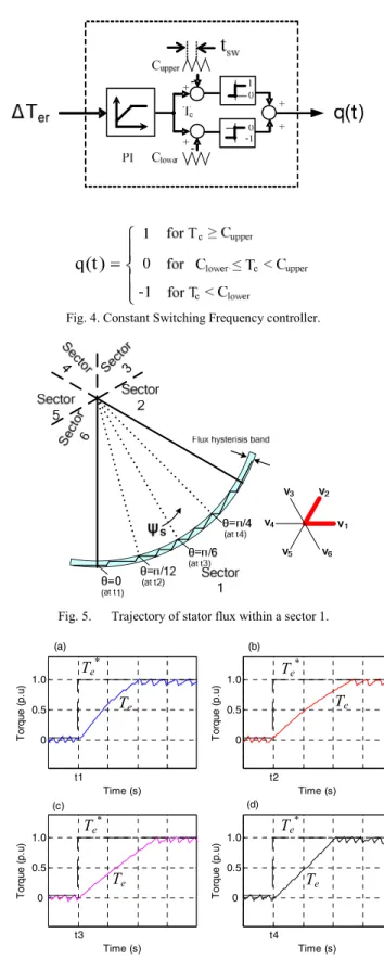
However, the hysterisis-based DTC scheme has two main disadvantages namely the high torque ripple and variable switching frequency of the inverter. Since the switching frequency is strongly affected by the hysterisis torque controller, it is possible to solve the problems by replacing the torque hysterisis comparator with a constant switching frequency controller as illustrated in Fig. 4. As reported in [9]
and [10], this simple modification has greatly achieved in obtaining constant switching frequency as well as torque ripple reduction. In order to establish a constant switching frequency, the frequency of upper and lower triangular waveforms employed for constant torque controller is set at 4 kHz with a peak-to-peak of 100 units. For PI torque controller, the gain value of Kp and Ki are restricted to ensure the absolute slope of the output signal, Tc does not exceed the absolute slope of triangular carrier [7].
It is well known that, a fast instantaneous torque control can be achieved in DTC-hysterisis based structure since the torque and flux are directly controlled based solely on the instantaneous errors in torque and flux. However, it can be question that does the basic DTC algorithm is capable to give the fastest torque response for any operating condition?
III. DYNAMIC TORQUE PERFORMANCE IN DTC
This section will discuss the performance of dynamic torque when utilizing either the hysteresis-based DTC or constant switching frequency-based DTC (DTC-CSF) induction machine drives with speed control as the speed reference is subjected to change for different operating conditions as follows
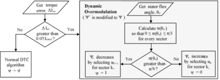
A. A Step Change of Speed Reference as the Stator Flux Angle within a Sector is at θ =0, π/12, π/6 or π/4 rad
For example, a step change of speed reference is applied (from 0.85 to 1.0 p.u) as the trajectory of stator flux in counter-clockwise rotation reaches at either one, θ =0, π/12, π/6 or π/4 rad as indicated in Fig. 5. The simulation results of dynamic torque performances for every given stator flux angle are depicted in Fig. 6. Apparently, a faster torque transient response is achieved when a step change of speed reference is applied at θ =0 or θ = π/4 rad. This is due to the fact that, the duration of appropriate active voltage vector applied that produces a larger stator flux tangential component is longer. Thus results in a quicker flux position changed and a faster dynamic torque response as well. In this case, the appropriate voltage vector for θ = 0 rad is v1, while the appropriate voltage vector for θ = π/4 rad is v2 (see Fig.
5). On the other hand, the on-duration of these application of voltage vectors are shorter and are alternately switched more often during the torque transient condition for the case of θ=π/12 or π/6 rad, thus results in a slower change of stator flux position as well as torque transient.
Fig. 4. Constant Switching Frequency controller.
Fig. 5. Trajectory of stator flux within a sector 1.
Fig. 6. A step change of output torque at a different stator flux angle, (a) θ
= 0 rad (b) θ = π/12 rad (c) θ = π/6 rad (d) θ = π/4 rad.
t1 0 0.5 1.0
Time (s)
Torque (p.u)
t2 0 0.5 1.0
Time (s)
Torque (p.u)
t3 0 0.5 1.0
Time (s)
Torque (p.u)
t4 0 0.5 1.0
Time (s)
Torque (p.u)
(a) (b)
(c) (d)
Te*
Te
Te*
Te
Te*
Te
Te*
Te
PEDS2009
B. A Step Change of Speed Reference from Different Level Speed Operations
In this case, a step change of speed reference is applied to analyze the performance of dynamic torque from different level speed operations. For instance, the number of simulations were performed for a step change of speed reference such that 0.25 p.u to 0.5 p.u, 0.5 p.u to 0.75 p.u and 0.75 p.u to 1.0 p.u, when the stator flux angle is at θ = π/6 rad (the worst case). The simulation results obtained are plotted in the same graph (for convenience to compare the dynamic torque performances) as depicted in Fig.7. Obviously, the fastest torque response is achieved when the speed reference is changed for the lowest speed operation that is from 0.25 p.u to 0.5 p.u. This is due to the fact that, the positive slope of torque in the case application of active voltage vector, decreases as the speed increases. Thus, the dynamic torque performance becomes problematic at high speed operation. It is still a great interest for researchers to propose dynamic overmodulation in vector-controlled motor drives having a quick torque response particularly in field weakening region with six-step operation.
IV. PROPOSED DYNAMIC OVERMODULATION METHOD Until now, no study of dynamic overmodulation in DTC- hysteresis based structure has been reported to achieve fast dynamic torque control. This paper present a very straightforward dynamic overmodulation utilized in DTC- Constant Switching Frequency (CSF) controller. The DTC- CSF scheme offers constant switching frequency and hence reduced torque ripple by replacing the 3-level hysteresis torque comparator with a constant switching frequency torque controller as reported in [9]. Fig. 8 shows the structure of DTC-CSF with a proposed ‘modified flux error status’
block, which is responsible to perform the proposed dynamic overmodulation. Notice that with the proposed dynamic overmodulation, the simple structure of basic DTC- hysteresis-based is retained in DTC-CSF.
Fig. 7. Waveforms of output torque for a different step change of speed reference, (a) 0.25 p.u to 0.5 p.u, (b) 0.5 p.u to 0.75 p.u, or (c) 0.75p.u to 1.0
p.u, when stator flux angle at θ = π/6 rad.
In the proposed dynamic overmodulation method, the dynamic condition is defined when the torque error exceeds 5% of rated torque. As the dynamic condition is encountered, the original stator flux error status, ψ+ is modified based on information of flux position, θψ to produce the appropriate flux error status ψ-. In this way, the active voltage vector that produces the largest tangential flux component is switched and held on, to create the largest increase in load angle and hence rapid dynamic torque. The operation of the modification flux error status to perform the proposed dynamic overmodulation can be described as illustrated in flow chart in Fig. 9.
Figure 10 illustrates the two possible selection of voltage vectors (i.e uk+1and uk+2) during dynamic condition as the stator flux is in sector k+1. The sector is further subdivided into two, namely subsector I and subsector II. The effect of selection of the voltage vectors on the dynamic torque performance will be investigated as the stator flux vector is located within subsector I and subsector II. To study this, the torque equation (6), which expressed torque in terms of stator flux, rotor flux and the angle between the two fluxes will be used.
sr r r s s
e m ψ ψ sinδ
L σL
L 2
T =3 (6)
where σ is the total leakage factor, ψs is the stator flux linkage, ψr is the rotor flux linkage, Ls, Lr and Lm are the motor inductances and δsr is the angle between stator flux linkage space vector and rotor flux linkage space vector.
Look-up Table (voltage
vector selector) CSF
Controller [9]
Modification of flux error status Flux
hysteresis comparator
Stator flux and torque estimator Tref
T ψref
ψs θψ
+
- -
ΔTer q(t)
Ψ+ Ψ-
Voltage Source
Inverter IM
Sa
Sb
Sc
Vdc
+
+ -
Fig. 8. Proposed structure for dynamic overmodulation in DTC-CSF based
Fig. 9. The operation of the proposed dynamic overmodulation
t3 0
0.5 1.0
Time (s)
Torque (p.u)
(a)
(b) (c) Tref
PEDS2009
It is obvious from the Fig. 10, that the two vectors will give different values of δsr. To obtain the fastest torque response, the vector that gives the largest stator flux tangential component and hence the largest change in δsr
should be selected. It can be easily seen from the figure that, selecting uk+1 and uk+2 will ensure the fastest torque response is achieved when the stator flux is located in subsector I and subsector II respectively. The dynamic of the torque will not only depend on these voltage vectors but will also depend on:
(a) the position of the stator flux at which the instant they are applied, and (b) the speed of the rotor as discussed in previous section.
Fig. 10. Effects of selecting different switching under dynamic condition.
V. SIMULATION RESULTS
The simulation of the DTC induction motor drive with the proposed overmodulation strategy was performed using MATLAB/SIMULINK simulation package. The DTC-CSF system and induction machine parameters used in the simulation are given as tabulated in Table II.
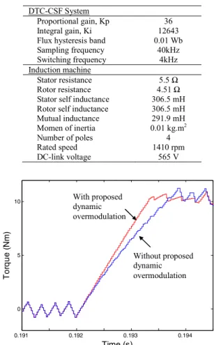
Fig. 11 compares the output torque performances during dynamic condition when a step change of speed reference is applied (0.85 p.u to 1.0 p.u). From the Fig. 11, it can be seen that a faster torque response is achieved in the DTC with the proposed dynamic overmodulation than that obtained in the DTC without dynamic overmodulation. Fig.
12 shows the performances of stator flux and d-q current components (correspond to the results obtained in Fig. 11).
Apparently, a sharp flux weakening is resulted during the dynamic condition in the proposed method. The sharp flux weakening occurs since the proposed algorithm selects only single active voltage vector during transient condition that produce the largest tangential flux component to achieve the fastest dynamic torque response.
TABLE II
DTC-CSFSYSTEM AND INDUCTION MACHINE PARAMETERS
DTC-CSF System
Proportional gain, Kp 36
Integral gain, Ki 12643
Flux hysteresis band 0.01 Wb Sampling frequency 40kHz Switching frequency 4kHz Induction machine
Stator resistance 5.5 Ω
Rotor resistance 4.51 Ω
Stator self inductance 306.5 mH Rotor self inductance 306.5 mH Mutual inductance 291.9 mH Momen of inertia 0.01 kg.m2
Number of poles 4
Rated speed 1410 rpm
DC-link voltage 565 V
Fig. 11. Output torque transient when a step change of speed reference is applied for (a) DTC without overmodulation (b) DTC with the proposed
The proposed dynamic overmodulation is capable in achieving fast dynamic torque response for a wide speed operation including the field-weakening region with six-step waveform. It can be shown that, a fast dynamic torque response is achieved since a phase stator voltage is suddenly changed from PWM to six-step operation when the dynamic condition is encountered as depicted in Fig. 13. Figure 14 illustrates the effect of stator flux position and rotor speed on the dynamic torque response with and without the proposed technique. In this case the dynamic torque condition is performed by applying a step change of speed from ω1 (initial speed) to 1.25 times higher than ω1 as the stator flux rotation reaches at either one, θ =0, π/12, π/6, 3π/12 or π/6 rad.
Obviously, a poor dynamic torque performance may result when the dynamic condition occurs at high speed operation and/or the flux position is at around the middle part of flux sector. Through the proposed dynamic overmodulation, a lesser rise time Δtrr of torque which means a faster dynamic torque response is achieved than that obtained in DTC without dynamic overmodulation.
0.191 0.192 0.193 0.194
0 5 10
Time (s)
Torque (Nm)
Without proposed dynamic overmodulation With proposed
dynamic overmodulation
PEDS2009
Fig. 12. Performances of DTC-CSF during dynamic torque condition for (a) without proposed dynamic overmodulation and (b) with proposed
dynamic overmodulation.
Fig. 13. Proposed dynamic overmodulation in field weakening region with six-step mode.
VI. CONCLUSION
Through the proposed dynamic overmodulation method, a quick dynamic torque control can be achieved by selecting a voltage vector that produces the largest tangential flux component. The proposed method is capable in obtaining the fastest dynamic torque control for any operating conditions including the field weakening region with six-step mode. The proposed dynamic overmodulation resulted in a simple hysteresis-based structure as originally proposed by [7]. Only minor modification is needed and no SVM and hence voltage
reference are required to be generated. Most of the main components of the basic DTC hysteresis-based structure are retained.
Fig.14. Effects of stator flux position (in a sector) and rotor speed on dynamic torque performance for (a) DTC with the proposed dynamic overmodulation and (b) DTC without proposed dynamic overmodulation.
ACKNOWLEDGMENT
The authors would like to thank the Universiti Teknikal Malaysia Melaka for providing the funding for this research.
REFERENCES
[1] DW Chung and SK Sul, “A new dynamic overmodulation strategy for high performance torque control of induction motor drives”, 14th Applied Power Electronics Conference and Exposition (APEC 99), Vol 1, pp 264-270, 1999.
[2] J. Holtz, W. Lotzkat, and A. Khambadkone, “On continuous control of pwm inverters in the overmodulation range including the six-step mode,” IEEE Trans. on Power Electronics, vol. 8, no. 5, pp. 546–553, Oct. 1993.
[3] A. M. Khambadkone and J. Holtz, “Compensated synchronous pi current controller in overmodulation range and six-step operation of spacevector-modulation-based vector- controlled drives,” IEEE Trans.
Ind. Electron., vol. 49, no. 3, pp. 574–580, Jun. 2002.
[4] T. Habetler, F. Profumo, M. Pastorelli, L. Tolbert. “Direct Torque Control of Induction Machines Using Space Vector Modulation”. IEEE Trans. on Industry Applications, 28(5):1045–1053, September/October 1992.
[5] T. G. Habetler, F. Profumo, and G. Griva, “Performance evaluation of a direct torque controlled drive in the continuous PWM-square wave transition region,” IEEE Trans. Power Electron., vol. 10, no. 4, pp.
464-471, 1995.
[6] Tripathi, A. M. Khambadkone, S.K. Panda, “Dynamic Control of Torque in Overmodulation and in the Field weakening region,” IEEE Transactions on Power Electronics, vol. 21, No. 4, pp. 1091-1098, July 2006.
[7] Takahashi I, Naguchi T, “A new quick-response and high efficiency control strategy of an induction motor,” IEEE Trans. Industry Applications, vol. IA-22, no. 5, pp. 820–827, 1986.
[8] H. Mochikawa, T. Hirose, and T. Umemoto, “Overmodulation of voltage source pwm inverter,” in Proc. JIEE Int. Soc. Conf., 1991, pp.
466–471.
[9] N. R. N. Idris and A. H. M. Yatim “Direct torque control of induction machines with constant switching frequency and reduced torque ripple,” IEEE Trans. Ind. Electron., vol. 51, no. 4, pp. 758–767, Aug.
2004.
[10] N.R.N.Idris, C.L. Toh, and M.E. Elbuluk, "A New Torque and Flux Controller for Direct Torque Control of Induction Motor Drives" IEEE Transaction on Industry Application, Vol. 42, No. 6, pp. 1358-1365 Nov. 2006.
0.25 0.3 0.35 0.4 0.45
0 5 10
Torque (Nm)
0.25 0.3 0.35 0.4 0.45
0.4 0.6 0.8
Stator flux (Wb)
0.25 0.3 0.35 0.4 0.45
-200 0 200
Time (s)
Phase voltage (V)
0.1 0.14 0.18 0.22 0.26
0.9 1
Time (s)
Stator flux (Wb)
0.1 0.14 0.18 0.22 0.26
-5 0 5
Time (s)
d-q currents (A)
0.1 0.14 0.18 0.22 0.26
0.9 1
Time (s)
Stator flux (Wb)
0.1 0.14 0.18 0.22 0.26
-5 0 5
Time (s)
d-q currents (A)
(a) without proposed dynamic overmodulation
(b) with proposed dynamic overmodulation
id
iq
iq
Without proposed dynamic overmodulation
With proposed dynamic overmodulation
1.5
0.4 0.5 0.6 0.7
0 π/6 0.5
Torque transient time, Δtrr (ms)
Stator flux position, α(θψ) (rad.)
Initial speed, ω1 (p.u) 0.3
π/3 1.0 2.0 2.5
id
PEDS2009
![Fig. 3. Six sectors of stator flux plane and switching voltage space vectorsk-1 k+1 k+3 k-2 k+2 ψsurefuk+1Hexagonal boundary Locus of Flux reference u[6]*Note:](https://thumb-ap.123doks.com/thumbv2/9libinfo/9127475.411664/2.918.476.848.573.1039/sectors-switching-voltage-vectorsk-ψsurefuk-hexagonal-boundary-reference.webp)