國立臺灣大學工學院材料科學與工程學研究所 博士論文
Graduate Institute of Materials Science and Engineering College of Engineering
National Taiwan University Ph.D. Dissertation
含釩鋼中界面析出之顯微結構及模型之研究
A study of interphase precipitation in Fe-V-C steels:
the microstructure and the modeling
陳孟揚 Meng-Yang Chen
指導教授:楊哲人 博士 Advisor: Jer-Ren Yang, Ph.D.
中華民國 102 年 10 月 October 2013
Acknowledgement
In 28 August 2011, it was my first time to come to Europe and to start over an unexpected academic life in France. Before that day, studying abroad was an unexpected event in my life. Now, these dreams finally come true and I am about to have my first PhD defense in the end of July 2013. Before leaving the campus, I would like to thank the following people who kindly give me a hand to accomplish the present thesis:
I would like to thank the France Institute in Taipei and the National Taiwan University to provide the scholarship, enabling me to concentrate on my studies in France. Meanwhile, I would like to thank the staff in office of international affairs to help me about the Dual-degree diploma application. I would also thank Professor Yang and his group members to encourage me to make me dream to come true. You guide me to enter the research field of materials science, provide research instruments, and share your research knowledge. These all delight me interests in metallurgy of steel.
I would like to thank the whole members of SIMaP for their assistances to help me to start my European life and for their fruitful discussions. I want to express my appreciations to Marc Verdier in helping me to carry out the experiments of nanoindentation, and Joelle Calabro, Frederic Charlot, and Florence Robaut in CMTC to help me on the SEM and EBSD analysis, respectively. I specially thank Professor Yves Bréchet to kindly welcome me to joint his research group. The model came up with you and Professor Militzer is the core of the present thesis. Finally, I would like to thank Professor Mohamed Gouné for his collaborations and efforts in the present thesis.
The modeling of interphase precipitation becomes valuable with your helps and supervisions.
i
I would like to thank my friends in France and in Taiwan. With your supports and accompanies, I do not feel along in my Ph.D. career. Finally, I would like to devote the whole thesis to my families. You give me everything and thank you to let me have the chance to explore this world.
ii
中文摘要
本論文針對含釩中碳鋼的肥粒鐵基地中的兩種碳化物: 界面析出碳化物和纖 維狀碳化物進行探討。論文內容可以分為三部分:顯微結構、理論模型、以及機械 性質。
在論文第一部分,我們主要利用電子顯微鏡 (光學顯微鏡、穿透式電子顯微 鏡、掃描式電子顯微鏡)去了解不同碳化物的形貌差異以及顯微結構的表徵,並就 觀察結果討論碳化物在進行形貌轉換時的可能機制。其結果指出形貌轉換時機取 決於相變態過程中的界面移動速度,沃斯田鐵相變態形成肥粒鐵初期,肥粒鐵加 上界面析出物為首要共析反應,在相變態進行過程,由於驅動力下降導致介面移 動速度變慢,纖維狀析出物即開始形成。
由於僅藉由電子顯微鏡的觀察並無法去了解並預測界面析出物和相變態溫度 間的相依性,因此我們進而發展了一套新的理論模型來描述界面析出之現象,而 在論文第一部份藉由電子顯微鏡的觀察結果和量測數據,則可用來確認我們所發 展的模型的可行性。理論模型的發展主要是和法國 Yves Brechet 教授和 Mohamed Goune 兩位教授一起合作之結果,所發展的模型稱為 “superledge”模型。有別 於先前已發表的模型,我們所發展的模型同時考慮了兩個界面析出的特性: (1) 沃 斯田鐵至肥粒鐵的相變態由 ledge 機制完成; (2) 析出過程伴隨相變態進行。在 給定材料組成及相變態溫度下,superledge 模型可以預測三點特性: (1) 界面析 出 物 的 層 間 間 距 (sheet spacing); (2) 界 面 析 出 物 的 層 內 間 距 (particle spacing),以及 (3) 相界移動速度 (interface velocity)。其計算結果和已發 表的參考文獻所量測的數據比較下,我們所發展的 superledge 模型呈現良好的預 測能力。
最後,奈米硬度壓痕技術被用以檢測界面析出物對肥粒鐵的強化效果。有別 於傳統的拉伸試驗所得到的巨觀機械性質,藉由奈米硬度機微小壓痕的優點,單 一肥粒鐵的機械性質可以被獨立分析,且析出強化值的大小可以被明確地定量。
我們藉由改變相變態的溫度來取得界面析出物於肥粒鐵基地內的分布情況,並依 其奈米硬度所量測的結果來討論碳化物大小、層間間距、以及層內間距對 Orowan 強化機制的影響。其所量測結果和理論值比較下有良好的一致性,其結果指出奈
iii
米硬度壓痕對析出強化機制的研究相當有幫助。
總體而言,於本研究論文所呈現的結果有助於提供中碳合金鋼中的析出物(界 面析出、纖維狀析出)之顯微特徵以及發展機制。並發展出一新的模型去探討相變 態溫度和合金組成對碳化物發展的影響,最後再利用新的奈米硬度壓痕技術去了 解析出物對肥粒鐵基地內的強化效果。本論文的研究結果,已發表至以下之國際 期刊:
Scripta Materialia (已發表) Acta Materialia (已投稿)
Advanced Materials Research (已發表) ISIJ International (已投稿)
關鍵字: 超高強度鋼、碳化物、界面析出、模型、肥粒鐵、相變態、奈米硬度壓 痕
iv
Abstract
The present thesis aims to examine the features of interphase precipitation and carbide fibers in a medium-carbon vanadium alloyed steel. It covers microstructure, modeling, and mechanical properties aspects of interphase precipitation and carbide fiber. The different features of interphase precipitation and carbide fiber are initially examined by TEM. The transition of the interphase-precipitated carbides to the fibrous carbides is discussed. It shows that the fibrous carbide would form at the later stage of the austenite-to-ferrite transformation, indicating that the occurrence of the fibrous carbide depends on the interface velocity. The conditions for the developments of the interphase precipitation and fibrous carbide are then clarified.
The obtained TEM results are then analyze to validate to a new model to elucidate the carbide precipitation with the growing ferrite phase. This new model is based on superledge mechanism of austenite-to-ferrite transformation. It deals with the ferrite and carbide nucleation rates and the driving force for austenite-to-ferrite transformation at the same time. The model gives good results at low transformation temperatures (< 700
oC) and reveals the evolutions of characteristic features of interphase precipitation with the progressive of austenite-to-ferrite transformation. The proposed superledge model is then extended to develop a model for carbide fiber growth and to understand the effect of carbon and solute contents on interphase precipitation in alloyed steels. .
Finally, local mechanical properties were characterized by the use of nanoindentation after the samples were isothermally transformed at different temperatures. It gives the elasto-plastic mechanical behaviors of the ferrite strengthened by interphase-precipitated carbides. The characteristic features of interphase-precipitated carbide predicted by the model are used to be incorporated with
v
tested mechanical properties. For the steel strengthened by the interphase-precipitated carbides, the contributed yield strength by these carbides is measured and the link between precipitation state and resulting mechanical properties is discussed. Finally, from a theoretical analysis, we show that precipitation state topology plays a key role in mechanical properties. The results presented in this thesis are expected to provide some original information related to the interphase precipitation in medium carbon alloyed steels.
The following research results have been published in the international journals:
Advanced materials research (EI), published Scripta Materialia (SCI), published
Institute of Iron and Steel of Japan (ISIJ), submitted Acta Materialia (SCI), submitted
Keywords: ultra-high strength steels, carbide, interphase precipitation, modeling, superledge, ferrite, transformation, nano-indentation
vi
本論文基於國立臺灣大學和法國格勒諾布爾大學綜合理工學院雙邊跨國雙學 位學程計畫並由臺灣大學國際事務處及法國在台協會協助之研究成果
The present thesis is based on an international dual-degree program signed up by National Taiwan University and University of Grenoble – Institute of Poly-technology and with the assistances of Office of International affairs, National Taiwan University and of France Institute of Taipei.
Les travailles presentes dans cette these sont un programme cotutelle signé par l'Université Nationale de Taiwan et de l'Université de Grenoble - Institut de Polytechnique, et avec les aides de bureau des affaires internationales de l'Université nationale de Taiwan et du bureau francais de Taipei.
vii
Contents
Acknowledgement ... i
中文摘要 ... iii
Abstract ... v
Contents ... viii
List of Figures ... xiii
List of Tables ... xxii
Chapter 1 ... 1
General Introduction ... 1
Chapter 2 ... 5
Literature Review ... 5
2.1 Precipitation in ferritic matrix ... 5
2.2 Precipitation in pearlitic ferrite ... 18
2.3 Models for interphase precipitation in vanadium alloyed steels ... 20
2.3.1 The models for interphase precipitation ... 24
2.3.2 The Superledge on the ferrite/austenite interface ... 58
2.3.3 The models for fibrous carbide ... 60
2.4 The mechanical properties of microalloyed steels ... 63
2.4.1 The strength of ferrite ... 64
2.4.2 Precipitation hardening in alloyed steels ... 66
2.4.3 The Orowan and Ashby-Orowan equations ... 69
2.5 Summary of the chapter ... 73
Chapter 3 ... 75
Microstructural Charactierization of Nb-V and V high strength rebar steels ... 75 viii
3.1 Introduction ... 75
3.2 Experimental Procedures ... 76
3.3 The Microstructure ... 77
a. Optical Microscopy... 77
b. Mechanical properties... 78
c. Transmission Electron Microscopy (TEM) ... 80
3.4 Quantitative estimations of the strengthening contributions ... 84
3.5 The occurrence of fibrous carbide in Steel-C ... 88
3.6 Conclusions ... 88
Chapter 4 ... 90
The TEM investigations of the features of the interphase-precipitated carbide and the fibrous carbide ... 90
4.1 Introduction ... 90
4.2 Experimental Procedure ... 90
4.3 Results and discussions ... 91
a. Macrostructure and Vickers Microhardness ... 91
b. Precipitation in ferrite ... 92
c. Precipitation in pearlitic ferrite ... 97
4.4 The conditions for the development of fibrous carbide ... 100
a. Effects of the transformation temperature ... 101
b. The effect of interface coherency ... 102
c. The alloying elements ... 103
4.5 Conclusion ... 105
Chapter 5 ... 107
The superledge model for interphase precipitation ... 107 ix
5.1 Introduction ... 107
5.2 The derivations ... 108
a. Assumptions ... 108
b. The classical ledge mechanism of austenite-to-ferrite transformation ... 110
c. The interaction of carbide with the growing ferrite phase ... 112
5.3 Parameters used for calculations ... 122
5.3.1 The ferrite and carbide nucleation rates ... 122
5.3.2 The diffusion mechanism of solute atom... 123
5.3.3 The interface mobility, M ... 124
5.4 Applications of the model and discussions ... 125
5.4.1 Prediction of the sheet spacing ... 125
5.4.2 Prediction of the particle spacing and the interface velocity ... 127
5.4.3 The effects of C and V contents on sheet spacing of IP ... 129
5.5 Conclusion ... 130
Chapter 6 ... 135
The Feature evolutions of interphase precipitation with the progression of austenite-to-ferrite transformation ... 135
6.1 Introduction ... 135
6.2 Experiments ... 136
6.3 Modeling ... 137
a. Summary of the superledge model for interphase precipitation ... 137
b. The mass balance of carbon and solute ... 138
6.4 Results ... 142
a. Microstructures of the interphase-precipitated carbide and the fibrous carbide ... 142
x
b. Modeling results ... 144 6.6 Discussions ... 145
a. The effect of carbide precipitation on the overall interface velocity ... 145 b. The minimum sheet spacing of interphase precipitation at a given transformation temperature ... 151 6.7 Conclusions ... 152 Chapter 7 ... 154 The effect of the interphase-precipitated carbide on the strengthening contribution to ferrite ... 154
7.1 Introduction and context of the study ... 154 7.2 The conversion of the depth-penetrating curve into mechanical properties ... 158
7.2.1 Bucaille’s approach... 158 7.2.2 The reliability of the processed data ... 162 7.3 Methodology: Measurement of the Orowan contribution of interphase precipitation ... 163
7.3.1. Orowan contribution ... 163 7.3.2. Determination of the increased yield strength and main results ... 166 7.4 Prediction of the Orowan contribution of ferrite strengthened by the interphase-precipitated carbides for different heating paths ... 169
7.4.1 Calculation of the Orowan contribution ... 170 7.4.2 Comparison between the calculated Orowan contribution and the measured one by nanoindentation ... 173 7.5 Discussion ... 175 7.5.1 The complex influence of heat treatment temperatures ... 175 7.5.2 The optimization of arrangement of the interphase-precipitated carbides
xi
under a fixed carbide volume fraction condition ... 177
7.5.3 Effects of Carbide distribution on Orowan strengthening: Comparison of the contribution of the random array carbides with the interphase-precipitated carbides. ... 179
7.6 Conclusions ... 184
Chapter 8 ... 186
General Conclusions and Perspectives ... 186
References ... 190
xii
List of Figures
Figure 2-1 The variations of carbide morphology with transformation temperatures [28]
... 6 Figure 2-2 Schematic diagram showing the interphase-precipitated carbides with planar spacing ... 6 Figure 2-3 The carbon concentration profile ahead of ferrite/austenite interface during interphase precipitation process [30] ... 7 Figure 2-4. Schematic illustration showing a unit ledge accompanying with features of interests. The meanings of each term are referred to the text. ... 8 Figure 2-5 The bowing mechanism for the curved interphase-precipitated carbides with irregular spacing [35]... 9 Figure 2-6 Schematic illustration of quasi-ledge mechanism of curved interphase precipitated carbides with regular spacing [35] ... 9 Figure 2-7 Fe-5Cr-0.2C (wt%) isothermal transformation at 650 oC for 30 min showing the interfaces associated with interphase precipitation (Right-hand side) and alloy fibers (Lef-hand side) [45] ... 14 Figure 2-8 Mo2C carbides with different morphologies in Fe-3.5Mo-0.22C (wt%) steels after isothermal transformation at 750 oC for 30 min. (a) interphase precipitation, (b) Widmanstätten arrays, and (c) Mo2C fibers [46] ... 17 Figure 2-9 Fe-4Mo-0.2C (wt%) steels showing the spacing and fineness of fibers changed as transformation temperature was varied from 850 oC (left-hand side) to 750
oC (right-hand side) [43] ... 18 Figure 2-10 Proposed ledge mechanism illustrating interphase precipitation in pearlitic ferrite [52] ... 19
xiii
Figure 2-11 The observed fibrous carbides in pearlitic ferrite, a dark-filed image [5] .. 19 Figure 2-12 The observed growth ledge on the pearlite/austenite interface [48] ... 20 Figure 2-13 Schematic illustration showing the sequences of interphase precipitation in the L-T model. (a) the first row of precipitates nucleate with a size of yp and generates the pseudo-phase boundary simultaneously; (b) the pseudo-phase boundary advances to the position where has sufficient solutes for further precipitation; the growth of the carbides in the first row is taken into considerations as well; and (c) carbides continue to grow, from the size y'p to y"p [12] ... 25 Figure 2-14 Schematic illustration showing the Rios’ model. The pseudo-phase is indicated as a shaded area. In the vanadium diffusion region, the pseudo-phase boundary changes linearly from the previous ledge riser to the latter one, with a final thickness, sf. ... 30 Figure 2-15 Schematic illustration showing the model proposed by Liu. The important time parameters are indicated in this figure. In his model, the process of interphase precipitation is a repeated force balance between the driving force, Fd, and the pinning force, Fp [57] ... 39 Figure 2-16 Interphase precipitation on a semi-coherent interface in L-Z model. (a) a ledge developed on the interface; (b) the ledge expands laterally and gradually increases its height; and (c) another precipitation process occurs on the interface again as the ledge reaching a critical height. The corresponding concentration profile is presented.
[13] ... 52 Figure 2-17 The developments of interphase precipitation on an incoherent interface in L-Z model, the front of interface is curved for this case. (a, b) a ledge developed on the interface then grows laterally and increases its height, generating the flow of solutes
xiv
from the top to the previous row of precipitation (c) primary precipitation occurs on the top of ledge (the superledge); (d) the superledge continues to expand laterally, leading additional precipitation to form at the middle of superledge boundary; and (e) the diffusion of solute atoms along incoherent interphase boundary leads to further precipitation (secondary precipitation). [13] ... 56 Figure 2-18 Schematic illustrations showing (a) the developing of a unit ledge on allotriomorphic ferrite by diffusional transformation, and (b) geometric analysis of superledge development. [56] ... 58 Figure 2-19 Model illustrating the Mo2C carbides formed in spiky noduls.
Fe-4.10Mo-0.23C (wt%) isothermal transformation at 650 oC for 2 hours [46] ... 61 Figure 2-20 A comparison (a) interphase precipitation, and (b) fiber growth. [3] ... 62 Figure 2-21 A model describing the fiber precipitation in association with migrating austenite/ferrite interface [12] ... 63 Figure 2-22 Another model concerning the crystallographic basis. The carbide morphologies are controlled by θ1and θ2, where θ1 is the angle between slowest moving austenite/ferrite interface and grain boundary, and θ2 is the angle between slowest moving austenite/ferrite and austenite/carbide interfaces [61] ... 63 Figure 2-23 Schematic illustration showing Orowan bypass mechanism of dislocation through carbide. (a) a dislocation is going to pass by a particle in matrix; (b) the dislocation is bowed because of the resistance force exerting from the particle, and (c) the dislocation passed by the particle and left a dislocation loop around the particle .... 68 Figure 2- 24 Schematically illustration showing the regular square array of particles and their interaction with a dislocation proposed in Orowan model. ... 71
Figure 3-1 The optical metallography of (a) CB, and (b) UHSB showing that both of xv
them are consisted of ferrite and pearlite but the microstructure of UHSB is greatly refined [75]. The white phase is ferrite and the dark phase is pearlite. ... 76 Figure 3-2 Optical micrographs of UHSSBs revealing microstructures composed of ferrite and pearlite: (a)Steel-A; (b) Steel-B. ... 78 Figure 3-3 (a) Stress-Strain Curves of Steel-A and Steel-B, demonstrating apparent yield point and yield plateaus, and (b) local magnification at yield point... 79 Figure 3-4 The TEM micrographs showing typical inter-phase precipitated carbides in ferrite; specimens were deformed to different diameters and subsequently continuous cooling to the room temperature: (a) Steel-A; (b) Steel-B. Fig. 2(a) clearly showing that dislocations were pinned by these carbides. ... 81 Figure 3-5 Bright-field and dark-field images and corresponding diffraction patterns of carbides in Steel-A. (a) Bright-field image; (b) Dark-field image illuminated by 002 carbide reflection; (c) Corresponding diffraction; (d) Identified orientation relationship of carbides and ferritic matrix. ... 82 Figure 3-6 EDX analysis on nano-sized carbides in Steel-A demonstrating that were composed of niobium and vanadium. ... 82 Figure 3-7 The fine inter-lamellar spacing of pearlite in UHSSBs: (a) Steel-A; (b) Steel-B. It shows that the spacing is about 100 nm. ... 83 Figure 3-8 Representative TEM micrographs for the dislocation structures in ferrite matrix and corresponding two-beam conditions: (a) Steel-A; (b) Steel-B. ... 85 Figure 3-9 The VC fibers in Steel-C... 88
Figure 4-1 The optical micrograph of the microstructure of the sample austenitized at 1200 oC subsequently isothermally transformed at 650 oC for 1h. ... 91 Figure 4-2 TEM analysis on the area containing two carbide aggregates in ferritic
xvi
matrix. (a) a bright-field image. (b) the SADP, (c) the indexed SADP of the interphase-precipitated carbide, (d) the indexed SADP of the carbide fiber, (e) and (f) the dark-field image illuminated by carbide 002 reflection for the interphase-precipitated carbide and carbide fiber, respectively. ... 94 Figure 4-3 Transition of carbide aggregates (interphase precipitation, carbide fiber, and pearlite) during the austenite-to-ferrite transformation. ... 97 Figure 4-4 The observed interphase-precipitated carbide and carbide fiber in pearlitic ferrite. (a-c) the bright-field, dark-field images and associated SADP of the interphase-precipitaed carbide; (d-f) that for carbide fiber. ... 98 Figure 4-5 The HRTEM image of the carbide fiber in ferrite. (a) the lattice image, (b) the FFT diffractogram, and (c) the EDS analysis of carbide fiber. ... 100 Figure 4-6 (a) The selected area for EBSD analysis showing ferrite allotriomorphs, idiomorphs, and martensite; (b) Orientation map of the selected area; (c) a stereographic projection showing the martensite variants transformed from this prior austenite grain, and (d) coupling with measured martensite (M1) and ferrite (a1) orientations... 104 Figure 4-7 (a) A micrograph showing the calculated deviation angle of ferrite grains; the ferrite with carbide fiber is labeled, (b) a SEM image of the labeled ferrite grain, and (c) a larger magnification of (b). ... 104
Figure 5-1 The characteristic features of interphase precipitation focused in the present superledge model. ... 109 Figure 5-2 The proposed sequence of the development of a superledge originated from the ferrite/austenite interface. (a) a unit ledge forms on an interface with carbides; (b) the first ledge moves laterally and is pinned by carbides, and then another unit ledge nucleates on the top of it; (c-d) the ledge continues to increase its height to unpin from
xvii
carbides; (e) the superledge is able to move laterally again and then merge the neighboring superledges, and (f) the overall interface advances until carbides precipitate on the interface again, completing a cycle of interphase precipitation. ... 111 Figure 5-3 Coupling with experimental data to the calculated sheet spacing showing that good agreements with the sheet spacing measured at lower transformation temperatures (< 700 oC ). The experimental data is cited from Wilyman [92], Parson [52], and Miyamoto [74] ... 126 Figure 5-4 The calculated particle spacing. The composition studied by Parsons and Edmonds [52] has been used (0.5 wt%C, 0.82wt%Mn, 0.3wt%V, 0.026wt%) . ... 128 Figure 5-5 The calculated interface velocity from superledge model and ledge velocity;
The composition studied by Parsons and Edmonds [52] has been used (0.5 wt%C, 0.82wt%Mn, 0.3wt%V, 0.026wt%). ... 128 Figure 5-6 The calculated sheet spacing changing with C and V contents ... 130
Figure 6-1 The optical micrographs taken from samples isothermally transformed at (a) 670 oC; (b) 650 oC, and (c) 630 oC for 1h... 136 Figure 6-2 Schematically illustrations showing the decreasing in (a) α nucleation energy, and (b) transformation driving force for transformation with the progressive of γ→α transformation ... 139 Figure 6-3 Schematic illustrations showing the proposed sequence of interphase precipitation accompanied with composition changes. (a) initial structure consisted of austenite only; (b) ferrite grows into austenite without carbide precipitation; (c) the first row of carbides forms on the ferrite/austenite interface; (d) ferrite advances again in a distance of sheet spacing of interphase precipitation; (e) The second row of carbides forms, and (f) continuously ferrite and carbide alternatively grows and precipitates,
xviii
respectively. ... 141 Figure 6-4 The flow chart of iteration procedures ... 142 Figure 6-5 TEM micrographs of interphase precipitation and corresponding HRTEM lattice images taken on the samples transformed isothermally at: (a, d) 630 oC, (b, e) 650 oC, and (c, f) 670 oC. ... 143 Figure 6-6 The TEM micrographs of typical carbide fiber microstructure isothermally transformed at (a) 630 oC, (b) 650 oC, and (c) 670 oC ... 144 Figure 6-7 The calculated evolutions of (a) particle spacing and (b) sheet spacing with time at different transformation temperatures, showing that the sheet spacing becomes finer but particle spacing exhibit an opposite tendency as transformation proceeds. .. 145 Figure 6-8 (a) the calculated evolutions of overall interface velocity with time, and (b) the calculated evolution of ferrite thickening isothermally at 650 oC showing a good agreement with experimental data. ... 146 Figure 6-9 The ratio of υ υαγ / α at different transformation temperatures with the progressive of austenite-to-ferrite transformation of the steel studied ... 147 Figure 6-10 The proposed model for the formation of carbide fiber. (a) a unit ledge is pinned by carbides; (b) the growth of carbide exceeds that of ferrite, growing along the side of ledge, and (c) the ledge never unpins from pinning carbides, resulting in carbide fibers. ... 149 Figure 6-11 A comparison of measured particle spacing of different carbide aggregates measured at the samples isothermally transformed at 650 oC for 1h. The particle spacing of interphase precipitation and carbide fiber show distinctive two groups, indicating that the carbide fiber develops at the later stage of austenite-to-ferrite transformation. ... 150 Figure 6-12 TEM micrograph showing the transition of interphase precipitation to
xix
fibrous carbide; the previous ledged interface can be well-illustrated. ... 150 Figure 6-13 The boundary of the predicted sheet spacing coupled with experimental data (the solid points) measured at different transformation temperatures ... 152
Figure 7-1 A schematically illustration showing the main quantities presented in the depth-penetrating curve ... 156 Figure 7-2 The ideal condition of the deformation and recovery of specimen during the indentation test. ... 157 Figure 7-3 The illustration of sink-in and pile-up phenomena showing on the surface of specimen during indentation. ... 163 Figure 7-4 The microstructure of the as-received hot-drawn steel bar and the representative stress obtained by nano-indentation by using two different indenters. . 167 Figure 7-5 The heat treatments of the specimens ... 170 Figure 7-6 The obtained typical depth-penetrating curves of the steel studied by using (a) Berkovich indenter, and (b) Cubic-Corner indenter. ... 170 Figure 7-7 Schematic illustration of the geometric orientation of the sheet plane, carbide platelet, and the slip plane. ... 172 Figure 7-8 The calculated stress-strain curve for ferrite transformed at (a) 630 oC, (b) 650 oC, and (c) 670 oC; the strengthening contributions to the global strength of ferrite are indicated ... 174 Figure 7-9 The temperature-dependence of (a) sheet spacing, (b) carbide radius, (c) carbide volume fraction, and (d) theoretical Orowan strengthening with transformation temperatures... 176 Figure 7-10 The evolution of Orowan strengthening with the sheet spacing and carbide radius. The carbide volume fraction is given as 0.0067. ... 179
xx
Figure 7-11 The variation of the ratio of Orowan strengthening for interphase-precipitated carbide to that for random array carbide with carbide radius. (a-c) the particle spacing is fixed, and (d-f) the sheet spacing is fixed. ... 183 Figure 7-12 The ratio varying with the carbide volume fraction, fv and a normalized precipitate state parameter, λ/R. (a-c) the particle spacing is fixed, and (e-f) the sheet spacing is fixed. ... 184
xxi
List of Tables
Table 1-1 Chemical composition of steel studied ... 2
Table 2-1 The observed features and proposed mechanisms for the development of fibrous carbide ... 13 Table 2-2 A summary of the existing models for interphase precipitation in vanadium alloyed steels ... 23 Table 2-3 The equations for chemical or cutting strengthening mechanisms ... 69 Table 2-4 The used particle spacing in different approaches... 73
Table 3-1 Chemical compositions of Steel-A and Steel-B (wt%) ... 77 Table 3-2 The microstructural features of UHSBs ... 78 Table 3-3 The mechanical properties of UHSBs ... 79 Table 3-4 The parameters of dislocation density calculations obtained via TEM ... 86 Table 3-5 The summary of strengths contributed from different mechanisms ... 86
Table 5-1 The experimental data used for supporting the proposed numerical models 109 Table 5-2 A summary of the equations used in the calculations ... 121 Table 5-3 The parameters used in the calculations ... 125
Table 6-1 The features of interphase precipitation measured by TEM ... 142
Table 7-1 List of c* given in Dao’s study [108] ... 159 xxii
Table 7-2 The representative strains associated with different included angle [104] ... 160 Table 7-3 Mechanical properties of ferrite from nano-indentation of the as-received materials ... 167 Table 7-4 The strengthening contribution to the global strength of ferrite in the steel studied ... 174 Table 7-5 The estimated strain hardening exponent at different transformation temperature ... 174
xxiii
Chapter 1
General Introduction
Owing to increase the strength of steel without modifying the main microstructure, precipitation hardening has been known to be an efficient way to reach this goal. The basic idea is to form high density of carbides dispersed in matrix by introducing certain strong carbide-forming elements, for example, Ti, Nb, Cr, V …etc. Then, precipitation hardening can be used to develop advanced ultra-high strength low-alloyed steels in automobile and construction applications. The mechanical properties of these products are associated with the size, distribution, density, and morphology of the carbides. In addition to pearlitic cementite (Fe3C) and supersaturated precipitation, there are two special carbide aggregates that have been received great attentions in these years: the interphase-precipitated carbide and the fibrous carbide.
For the case of interphase precipitation, the precipitation process is related to the ledge migration of ferrite/austenite interface. The precipitation of carbide mainly occurs on the relative immobile terrace plane of ferrite matrix. However, the mobile steps are carbides free because of their high mobility. Comparing to the interphase-precipitated carbides, the number of studies dedicated on fibrous carbides is very limited and there is still a lack of data and analysis that rest on both experimental and theoretical data.
Edmonds firstly discussed the different growth mechanisms of interphase precipitation and carbide fiber, and concluded that the higher Mn addition, the higher volume fraction of fibrous carbide in ferritic matrix. In certain circumstances, the platelet interphase-precipitated carbide would transit into a fibrous morphology. However, the competition in the growth mechanisms of these two carbide aggregates is still unclear.
1
The as-received materials are medium-carbon steels bars micro-alloyed with V and V-Nb provided by Taiwan Tunghe Steel Enterprise. The detailed chemical composition is summarized as follows:
Table 1-1 Chemical composition of steel studied
Diameter C Si Mn V Nb
Steel-A 16 mm 0.37 0.26 1.10 0.26 0.04
Steel-B 36 mm 0.34 0.34 1.37 0.27 0.05
Steel-C 43 mm 0.36 0.33 1.35 0.33 -
The steel bars with different diameters were manufactured in order to meet specific
requirements of construction ADDIN EN.CITE
<EndNote><Cite><Author>Aoyama</Author><Year>2001</Year><RecNum>310</Re cNum><DisplayText>[1]</DisplayText><record><rec-number>310</rec-number><for
eign-keys><key app="EN"
db-id="fswe0zeeo59t0se2fw7pdtx52pwxtw2taxfe">310</key></foreign-keys><ref-typ e name="Book">6</ref-type><contributors><authors><author>Aoyama, H.</author></authors></contributors><titles><title>Design of Modern Highrise
Reinforced Concrete Structures</title></titles><dates><year>2001</year></dates><publisher>Imperial
College
Press</publisher><isbn>9781860942396</isbn><urls><related-urls><url>http://books.
google.fr/books?id=LO2R2w5xsfoC</url></related-urls></urls></record></Cite></En dNote>[. In steel-C, the interphase-precipitated carbides and the fibrous carbides are both observed in ferritic matrix by TEM. It could be resulted from (1) sufficient Mn
2
addition, and (2) the larger specimen leads to a slower cooling rate. Therefore, steel-C could be very suitable for investigating the morphological features of the interphase-precipitated carbide and the fibrous carbide and for understanding the competition of these two carbide aggregates. The microscopic information is then useful either for developing the models to describe the formation mechanisms of interphase precipitation and fibrous carbide or for interpreting the effect of carbide distribution on the strengthened ferritic matrix.
In the present thesis, Chapter 2 firstly provides a review of the precipitation of carbide in alloyed steels. The review concerns with microstructure, modeling, and mechanical properties. Chapter 3 then shows the detailed investigations of these steel bars. The strengthening contribution of the interphase-precipitated carbide has been quantitatively estimated, and the motivation of the present dissertation is subsequently pointed out by the observations of the two carbide aggregates in steel-C. Comapred to Steel-A and Steel-B, Steel-C contains sufficient Mn addition (1.35 wt%) and is microalloyed with V only, which is therefore used in the following chapters. Chapter 4 discusses the competition between the interphase-precipitated carbide and the fibrous carbide based on TEM investigations. The formation of interphase precipitation and carbide fiber have been clarified and compared. The results show that the change in carbide morphology is controlled by the velocity of interface, related to the thermodynamic and kinetic of austenite-to-ferrite transformation. A model is then proposed to describe the sequence and to predict the features of interphase precipitation.
The modeling works are based on an international program in collaboration with Professors Bréchet, Gouné and Militzer. The developments of model and its relevant applications are presented in Chapter 5 and Chapter 6. The model now is successfully developed and called as the superledge model. By giving the transformation temperature
3
and the associated chemical composition, it predicts the features of interphase precipitation by considering the interaction of the carbide and mobile steps on a ledged ferrite/austenite interface. Besides, this model is also extended to understand the feature evolutions of interphase precipitation with the progressive of austenite-to-ferrite transformation, and then a mechanism is proposed for the carbide fiber formation.
Finally, the ferrite strengthened by interphase precipitation is examined by nanoindentation. By this approach, the work hardening behavior and the yield strength of ferrite at different transformation temperature can be presented, and the corresponding elasto-plastic behavior can be simulated as well. Furthermore, a method for measuring the Orowan contribution of interphase precipitation in ferrite is proposed.
The obtained results are in good agreement with those calculated. Finally, the effect of the arrangement of interphase-precipitated carbides on resulting strengthening is discussed.
The present thesis entitled as “A study of interphase precipitation in Fe-V-C alloyed steels: the Microstructure and the Modeling” attempts to give a comprehensive study of the features of interphase precipitation and carbide fiber and to inter-connect their relations of microstructures, modeling, and mechanical properties.
4
Chapter 2
Literature Review
The interphase-precipitated carbides and the fibrous carbides have been studied in the ferrite matrix. It has been shown to improve the strength of steel efficiently. It is worth understanding the formation mechanisms of the two carbides and their characteristic features. In the past decades, the precipitation of the interphase-precipitated carbide and of the fibrous carbide had been observed either in proeutectoid ferrite [2-4] or in pearlitic ferrite [5-8]. The relevant models were then proposed to illustrate the developments of interphase precipitation [9-13] and carbide fiber [3]. Besides, the relations of the mechanical properties with the observed microstructures have been proposed as well [14-20]. In this chapter, the microstructures, the models, and the mechanical properties of interphase precipitation in micro-alloyed steels are reviewed. This literature survey is essential to clarify the unsolved issues for the further investigations.
2.1 Precipitation in ferritic matrix a. The interphase precipitation
The interface is known to be a topic of interest in the field of solid transformation [21-26]. The term “interphase precipitation” represents the carbide nucleation process repeats periodically during the austenite-to-ferrite transformation, resulting in a sheeted structure[2, 27]. Such carbide dispersion and morphology have been reported to depend on the transformation temperature. One of the proposed classifications is shown in Figure 2-1.
5
Figure 2-1 The variations of carbide morphology with transformation temperatures [28]
The microstructure of the interphase-precipitated carbide was studied by Honeycombe et al. via TEM in different alloyed steels [27, 29], and the ledge mechanism of austenite-to-ferrite transformation is proposed to be operated during transformation, as shown in Figure 2-2. The interphase-precipitated carbide obeys one variant of Baker-Nutting orientation relationships, {0 0 1}carbide || {0 0 1}α and <1 1 0>carbide || <1 0 0>α. The single variant selection of interphase-precipitated carbides is explained to minimize the interfacial energy and to maximize the diffusion efficiency of solute atoms.
Figure 2-2 Schematic diagram showing the interphase-precipitated carbides with planar spacing
6
The process of interphase precipitation (with planar spacing) is briefly described in Figure 2-3. During γ to α transformation, the formation of α increases the carbon content in front of the ferrite/austenite interface. As the carbon concentration reaches a critical value, alloy carbides would start to precipitate on the ferrite/austenite interface.
The formation of carbide lowers the carbon content ahead of interface, increasing the driving force for austenite-to-ferrite transformation. The interface then advances and the above process repeat periodically, leading to dense of carbides arranged in regular spacing.
Figure 2-3 The carbon concentration profile ahead of ferrite/austenite interface during interphase precipitation process [30]
The ledge mechanism of austenite-to-ferrite transformation is viewed as the spirit of interphase precipitation [31-34]. A typical ledge structure of interface contains a broad plane and a mobile step, which are illustrated in Figure 2-4. The overall growth rate of a ledged interface, V, depends on the ledge height, h, and its spacing, b:
s
V V h
= b (2-1)
7
where Vs is the step velocity, h is the ledge height, and b is the spacing of ledges.
Figure 2-4. Schematic illustration showing a unit ledge accompanying with features of interests. The meanings of each term are referred to the text.
Based on the point of view of Honeycombe et al., the broad interface is supposed to be semi-coherent. Ferrite follows {110}α || {111}γ Kurdjumov-Sachs orientation relationships with respect to the parent austenite. On the contrary, the mobile steps are incoherent. Based on the metallurgical considerations, these steps are assumed to be the preferred carbide nucleation sites. However, in the case of interphase precipitation, these steps move too fast during transformation, making the carbide nucleus difficult to nucleate on them. Instead, carbides prefer to precipitate on coherent/semi-coherent interfaces, leading to interphase precipitation.
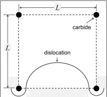
In addition to the planar interphase precipitation, other mechanisms had been proposed to explain the interphase precipitation with curved spacing. Ricks and Howell proposed the bowing mechanisms (for curved interphase precipitation with irregular spacing) and quasi-ledge mechanisms (for curved interphase precipitation for regular spacing) to illustrate the curved interphase precipitation [35, 36]. The bowing mechanism, as shown in Figure 2-5, requires the carbides to pin the moving interface. It
8
can be expected that the carbide density and the particle spacing in rows determine the resulting sheet spacing. For quasi-ledge mechanism (Figure 2-6), the interface breaks into austenite at the place where the particle spacing is relatively wider. The segment of the advancing interface accumulates sufficient carbon and solute, and then carbide starts to precipitate on its top. The newly formed carbide pins the advancing interface again, the mobile steps then move by sideway. Obviously, the carbide distribution determines which mechanism, bowing and quasi-ledge, is operated during transformation.
Figure 2-5 The bowing mechanism for the curved interphase-precipitated carbides with irregular spacing [35]
Figure 2-6 Schematic illustration of quasi-ledge mechanism of curved interphase precipitated carbides with regular spacing [35]
9
b. The carbide fiber growth
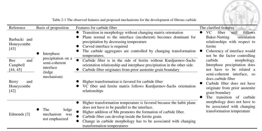
In addition to interphase precipitation, another carbide aggregate: carbide fiber, is usually found in Fe-Mo-C, Fe-Cr-C, and Fe-V-C steels as well, but the strengthening mechanism of fibrous carbide in ferrite is less discussed [37]. The observed features and proposed formation conditions for fibrous carbide are summarized in Table 2-1. Carbide fibers are known to be straight and branchless, generally growing in a single direction normal to the transformation interface. The occurrence of fibrous carbide depends on transformation temperature, chemical composition, and the nature of interfaces. The related literatures have been reviewed and the important concepts and ideas are summarized as follows:
(1) The carbide fiber in the Fe-V-C Steel
Generally, the addition of vanadium is widely used to strengthen steels by interphase precipitation hardening due to the temperature for precipitation is approximately close to austenite to ferrite transformation [29, 38]. The occurrence of alloy fiber in Fe-V-C steels is not greatly reported. Edmonds studied the VC fibers by varying cooling rate and by changing the content of Mn [3]. He found that as the amount of Mn was elevated from zero to 1.6 wt%, the density of VC fibers was increased of 50%.
The Mn has been reported to have strong effects on slowing down the advancement of the transformation interface [39]. Edmond’s works indicate that the interface mobility is an important role in carbide morphology determination. He suggested that a higher transformation temperature would be favored for the development of fibrous carbide and pointed out that the selection of habit plane is a
10
function of the transformation temperature. For interphase-precipitated carbide, its habit plane is expected to be as parallel to the interface because that minimizes the interfacial energy and maximizes the diffusion of solute atoms [28]. However, the habit plane of VC does not to be as parallel to the transformation interface at the high transformation temperature because the solute now requires sufficient energy [28]; the formation of fibrous carbide becomes possible. These results indicate that the change in carbide morphology requires changing the transformation temperature.
VC carbide is f.c.c structure. The Baker-Nutting orientation relationships [40, 41]
are commonly found for these carbides with respect to ferrite:
(
1 0 0) (
VC || 1 0 0)
α[
0 0 1] [
VC || 0 1 1]
αThe structure of VC fiber is identical as that of interphase precipitated VC carbide.
Berry had claimed that the VC fibers exhibited Kurdjumov-Sachs orientation relationships with respect to ferrite [42]:
(
1 1 1) (
VC || 1 1 0)
α1 1 0 || 1 1 1
VC α
The difference in orientation relationships implies the nucleation and growth of carbides follow different process. If the VC fibers follow Kurdjumov-Sachs orientation relationships with respect to ferrite, the nuclei of fibers are formed at the side of
11
austenite at the austenite/ferrite interface, then growing in austenite, instead of ferrite.
Otherwise, if Baker-Nutting orientation relationships are followed by ferrite and carbide, the development of carbides is related to ferrite, not austenite. The orientation relationships of carbide with respect to austenite reveal important information of where nucleation and growth of carbide occur. The detailed results and discussions will be presented in the next chapter
12
Reference Basis of proposition Features for carbide fiber The clarified features Barbacki and
Honeycombe [43]
Interphase
precipitation on a semi-coherent interface (ledge mechanism)
Transition in morphology without changing matrix orientation
Plane normal to the interface (incoherent) becomes dominant for precipitation by decreasing temperature
Curved interface is required
The carbide aggregates are controlled by changing transformation temperatures.
VC fiber still follows Baker-Nutting orientation relationships with respect to ferrite
Coherency of interface would not be the factor controlling carbide morphology.
Interphase precipitation does not have to be related a semi-coherent interface, so does carbide fiber
Carbide fiber does not have originate from prior austenite grain boundary
The transition of carbide morphology does not have to be associated with changing transformation temperature Bee and
Campbell [44, 45]
Carbide fiber is in the side of ferrite without Kurdjurmov-Sachs orientation relationship and interphase precipitation in the other side.
Carbide fiber originates from prior austenite grain boundary
Berry and Honeycombe [42]
Higher transformation is favored for carbide fiber
VC fiber and ferrite matrix follows Kurdjurmov-Sachs orientation relationships
Edmonds [3]
The ledge mechanism was not emphasized
Higher transformation temperature is favored because the habit plane does not have to be parallel to the interface.
Higher addition of Mn promotes the formation of carbide fiber.
Carbide fiber can develop inside the ferrite grain.
Change in carbide morphology has to be associated with changing transformation temperatures
Table 2-1 The observed features and proposed mechanisms for the development of fibrous carbide
13
(2) The carbide fiber in the Fe-Cr-C steel
The carbide fibers in isothermally transformed Fe-Cr-C steels were studied by Bee [44] and Campbell [45] et al. The interphase-precipitated carbides and the fibrous carbides were both observed among these works. From their TEM evidence, they pointed out that interphase precipitation was related to a stepped interface, but the carbide fiber was in associated with curved interfaces (Figure 2-7). They then concluded that the formation of the interphase-precipitated carbide or the fibrous carbide would be controlled by the coherency of interface.
Figure 2-7 Fe-5Cr-0.2C (wt%) isothermal transformation at 650 oC for 30 min showing the interfaces associated with interphase precipitation (Right-hand side) and alloy fibers (Lef-hand side) [45]
Furthermore, two kinds of carbide fiber were found (M7C3 or M23C6). The examinations showed that the chemistry of carbide depends on the transformation temperature only. As transformation temperature is lowered, the spacing of fibers becomes finer, and the chemistry of carbide changes from M23C6 to M7C3.
14
The crystal structures of M23C6 and M7C3 are f.c.c. and h.c.p., respectively. For M23C6, the orientation relationships of these fibers with respect to ferrite were identified as:
( ) ( )
23 6
1 1 1 M C || 1 1 0 α
23 6
1 1 0 || 1 1 1
M c α
Type I
which are known as Kurdjumov-Sachs orientation relationships. For M7C3, which the structure is h.c.p., the orientation relationships with ferrite had been identified as follows:
( ) ( )
7 3
0 0 0 1 M C || 0 1 1α
[ ]
7 3
1 1 2 0 || 1 0 0
M C α
Type II
Bee and Campbell considered the carbide morphology was related to crystallographic of ferrite/austenite interface. As austenite starts to decompose to ferrite, ferrite initially nucleates on prior austenite grain boundaries. In the growing stage, this ferrite nucleus would not possess any orientation relationships with respect to the austenite into which it is growing (for the case of allotriomorphic ferrite). The other side where growth of ferrite does not occur, the ferrite and austenite exhibit Kurdjumov-Sachs orientation relationships. Thus, it is expected that the carbide fibers would form predominantly at the side of austenite where the ferrite is growing into, and interphase precipitation would occur at the other side of ferrite/austenite interface that
15
follows Kurdjumov-Sachs orientation relationships. This argument is consistent with that proposed by Honeycombe et al. It implies that austenite/ferrite interfacial structures could be another factor on determining carbide morphologies but the above suggestions cannot explain the transition in carbide morphologies.
(3) The carbide fiber in the Fe-Mo-C steel
The carbide fibers formed in Fe-Mo-C steels were widely studied by Edmonds and Honeycombe et al [8, 46]. Three morphologies, interphase precipitation, Widmanstätten arrays, and carbide fibers were found in this alloyed system, as demonstrated in Figure 2-8.
The carbide in Fe-Mo-C steels is mainly Mo2C with h.c.p structure. The analysis on the diffraction patterns showed that there are two orientation relationships of carbides with respect to ferrite. The orientation relationships of Mo2C with respect to ferrite are:
(
0 0 1) (
α || 0 0 0 1)
Mo C2( ) ( )
2
1 1 1 || 1 2 1 0
α Mo C Type I
However, for the carbides that arranged in Widmanstätten way and interphase-precipitated carbide, the orientation relationships become to be:
( ) ( )
2
0 1 1α || 0 0 0 1 Mo C
( )
( )2
1 0 0 || 1 1 2 0
α Mo C Type II
16
Such orientation relationships were also confirmed by other studies.
Figure 2-8 Mo2C carbides with different morphologies in Fe-3.5Mo-0.22C (wt%) steels after isothermal transformation at 750 oC for 30 min. (a) interphase precipitation, (b) Widmanstätten arrays, and (c) Mo2C fibers [46]
c. The transition in carbide morphology
The change in carbide morphologies is an important issue in alloyed steels because it directly affects performed mechanical properties. The transition in carbide morphologies was investigated by Barbacki and Honeycombe in Mo and V containing steels by simply altering the transformation temperatures [43]. These fibers mainly originated from curved interfaces, and with different spacing as the transformation temperature was changed (Figure 2-9). Even though the carbide morphology and its distribution are controlled by the transformation temperature, the transition in carbide morphology should not be associated with altering the orientation of ferrite matrix.
Compared to Edmonds’ proposal, they thought that the carbide fibers were predominant at lower transformation temperatures. There explanation was based on both transformation kinetics of Mo containing steels and misfits that result from different crystal structures of carbide/ferrite and carbide/austenite. By decreasing the transformation temperature, the solute atoms would mainly diffuse along the incoherent
17
interface. For the ledge mechanism of austenite-to-ferrite transformation, the terrace plane was viewed as a semi-coherent interface for precipitation. Consequently, the carbide would like to precipitate on the mobile steps as the transformation temperature is lowered, and then grow in a direction perpendicular to the transformation front.
However, this feature is not seen in other systems. For Fe-Cr-C and Fe-V-C steels, the fibrous carbides were found to be majority at higher transformation temperatures, instead of lower transformation temperatures.
Figure 2-9 Fe-4Mo-0.2C (wt%) steels showing the spacing and fineness of fibers changed as transformation temperature was varied from 850 oC (left-hand side) to 750 oC (right-hand side) [43]
2.2 Precipitation in pearlitic ferrite
The pearlite reaction inevitably occurs after the interphase precipitation as the nominal content of carbon is increased. Previous sessions are all focused on the presence of carbides (interphase precipitation or carbide fiber) in proeutectoid ferrite. As the carbon and solute contents increase, the carbide precipitation is capable to occur in pearlitic ferrite [6, 47-50]. The interphase-precipitated carbides in pearlitic ferrite had
18
been reported to have smaller size and finer sheet spacing than that precipitated in proeutectoid ferrite [51] because certain amount of C is consumed by the formation of Fe3C. Parsons et al. [52] used ledge mechanism to interpret such phenomenon, as shown in Figure 2-10. Moreover, if sufficient manganese (13 wt%) is added, which decelerates austenite to ferrite transformation, carbide fibers were found in the pearlitic ferrite [5], as shown in Figure 2-11. However, the occurrence of fibrous carbide in pearlitic ferrite was not deeply addressed.
Figure 2-10 Proposed ledge mechanism illustrating interphase precipitation in pearlitic ferrite [52]
Figure 2-11 The observed fibrous carbides in pearlitic ferrite, a dark-filed image [5]
19
The presence of interphase precipitated carbide or VC fibers in pearlitic ferrite arises the problems on the nature of interface again. Zhou and Shiflet [48, 53] proposed the growth of pearlite in austenite is indeed associated with small ledges at the interface based on their TEM observations (Figure 2-12). The growing pearlite/austenite interface has been viewed as an incoherent interface [54, 55]. The observed interphase-precipitated carbide and fibrous carbide imply that the coherency of the interface would not be the main factor in determining carbide morphologies.
Figure 2-12 The observed growth ledge on the pearlite/austenite interface [48]
2.3 Models for interphase precipitation in vanadium alloyed steels
As discussed before, the proposed mechanisms of interphase precipitation are mainly based on microscopic observations. It was clearly showed that sheet spacing and carbide distribution depend on temperature. However, they are unable to give detailed understandings of precipitation processes and to give prediction of the features of
20
interphase precipitation as the transformation temperature and the chemical composition of steel are given. For examples, it is deficient to explain: (a) the repeat nucleation process of precipitation along the interface boundary; (b) the uniform size distribution of carbides in a sheet; and (c) the temperature-dependence of observed sheet spacing.
The prediction of microstructure is important for industry in manufacturing and casting materials. Out of this purpose, the numerical and computational models are therefore proposed to solve this problem by considering the thermodynamic and kinetic aspects of austenite-to-ferrite transformation and carbide precipitation. The experimental data from Honeycombe et al. and Ricks and Howell are mainly incorporated in the numerical models. According to the as-received materials, the models are limited to that proposed for vanadium alloyed steels. The basic propositions and the contributions of the proposed models are summarized in Table 2-2.
For the interphase precipitation in vanadium alloyed steels, the modeling work was initiated by Li and Todd. Their model is based on solute balance at the interface.
Sophisticated mathematical equations and treatments were used to obtain the ratio of sheet spacing to carbide width by firstly measure the interface velocity with a given sheet spacing. This ratio, in their view points, is independent of transformation temperatures and can be used to calculate the modeled parameters. Therefore, the sheet spacing at different transformation temperatures can be predicted. The calculated results exhibit good agreement with experimental works.
On the contrary, Lagneborg and Zajac (L-Z model) proposed a semi-analytical model by introducing the concepts of superledge and assuming a local equilibrium condition at the interface. The L-Z model is mainly focused on the relation between sheet spacing and transformation temperatures and the effects of carbon and vanadium contents on the sheet spacing was briefly discussed. In fact, their goal was to clarify the
21
effects of diffusion mechanisms of solute (volume or boundary diffusions) and natures of interface (coherent or semi-coherent) on interphase precipitation.
22
Table 2-2 A summary of the existing models for interphase precipitation in vanadium alloyed steels
Important assumptions Contributions Remarks
Bhadeshia [56]
- The minimum height of ledge is given The height of superledge has to be larger than the predicted minimum height
Li and Todd [12]
Vanadium re-distribution between austenite and ferrite and it accumulates at the interface
The nucleation of carbide does not interfere with interface migration
Transformation accomplished by advancing small steps, not a superledge
Vanadium diffuses in ferrite (volume diffusion)
Ratio of sheet spacing to carbide width can be obtained by measuring the boundary velocity where sheet spacing is known.
The ratio is independent of transformation temperature
Ledge mechanism is not highlighted
Dealt carbide precipitation with the growing ferrite phase
Sheet spacing, particle spacing, and carbide size can be predicted
Rios [10]
The stepped interface migrates at a constant velocity and its ledge height equals to the sheet spacing of interphase precipitation
Vanadium diffuses in pseudophase (volume diffusion)
Solubilities of solute and carbon are emphasized
Calculated velocity is half of that calculated by Li and Todd
The concept of pseudo-phase is also applied.
Stoichiometric composition of steel
Followed ledge mechanism
Predict the variation of sheet spacing with the transformation temperatures
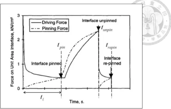
Liu [57]
Local para-equilibrium condition at the interface
Nucleation of carbide is accompanied with advancement of interface.
The ledge height is a constant value
Consider force balance between pinning force of carbide and transformation driving force.
Provide the precipitation start time.
Empirical expression of boundary diffusion is given
Ledge mechanism is not followed
The empirical boundary diffusivity of vanadium atom was presented.
Lagneborg and Zajac [13]
Local equilibrium at the interface
Interphase precipitation is accomplished by boundary diffusion of vanadium
Introducing the concept of superledge
Discussed the diffusion mechanisms and natures of interface
Revealed the composition-dependence (C, V, and N) of sheet spacing
The term of superledge was firstly incorporated in model development
23
The positions of the proposed models are summarized in Table 2-2. Among these models, the predicted sheet spacing in their works generally shows good agreements with experimental data at higher transformation temperatures. Each of them will be examined carefully and the assumptions will be reviewed as follows.
2.3.1 The models for interphase precipitation (1) The Model of P. Li and J.A. Todd
The model proposed by Li and Todd (the L-T model) is based on the coupling between growth of carbide and ferrite. The precipitate sheet widths, precipitation repeat periods and boundary velocities are formulated. Their final outputs are a ratio of sheet spacing to carbide size.
In the L-T model, the term “pseudo-phase boundary” was introduced in order to apply Zener’s solution for plate precipitate growth and the following assumptions were made [58]:
a. the solute concentration is constant and equal to the average concentration of the sheet of interphase-precipitated carbides.
b. mass balance is applied at the interface
c. average solute concentration in ferrite at the interface boundary is constant d. The motion of interface does not influence the carbide nucleation.
e. The passage of ledge is accomplished by advancing small steps. The row of carbides and the layer of ferrite are stacked layer by layer.
Figure 2-13 highlights the sequences of interphase precipitation in L-T model. As the first row of precipitates formed, the pseudo-phase is generated just ahead of the
24
precipitates (Figure 2-13). The interphase-precipitated carbides are assumed to be small and uniformly distributed along the interface boundary, enabling the growth of precipitates in row to be approximately planar. The precipitates in the first row will grow with time, so does the austenite/ferrite interface boundary. Until the interface boundary moves away, accumulating sufficient solutes for further precipitation, the second cycle of interphase precipitation occurs. It should be kept in mind that the lateral growth of ledge is accomplished by small steps and the growth of carbide with interface motion is highlighted.
Figure 2-13 Schematic illustration showing the sequences of interphase precipitation in the L-T model. (a) the first row of precipitates nucleate with a size of yp and generates the pseudo-phase boundary simultaneously; (b) the pseudo-phase boundary advances to the position where has sufficient solutes for further precipitation; the growth of the carbides in the first row is taken into considerations as well; and (c)
carbides continue to grow, from the size y'p to y"p [12]
Coupling with the experimental work from Honeycombe et al., it has found that the sheet spacing of interphase precipitation and the diffusivity of solute element can be expressed as:
' ( )1/2
c e V
y =K D (2-2)
25

![Figure 2-3 The carbon concentration profile ahead of ferrite/austenite interface during interphase precipitation process [30]](https://thumb-ap.123doks.com/thumbv2/9libinfo/9601474.629030/34.892.255.673.508.743/figure-concentration-profile-ferrite-austenite-interface-interphase-precipitation.webp)
![Figure 2-6 Schematic illustration of quasi-ledge mechanism of curved interphase precipitated carbides with regular spacing [35]](https://thumb-ap.123doks.com/thumbv2/9libinfo/9601474.629030/36.892.209.684.825.1053/figure-schematic-illustration-mechanism-interphase-precipitated-carbides-regular.webp)
![Figure 2-10 Proposed ledge mechanism illustrating interphase precipitation in pearlitic ferrite [52]](https://thumb-ap.123doks.com/thumbv2/9libinfo/9601474.629030/46.892.169.759.459.662/figure-proposed-mechanism-illustrating-interphase-precipitation-pearlitic-ferrite.webp)
![Figure 2-12 The observed growth ledge on the pearlite/austenite interface [48]](https://thumb-ap.123doks.com/thumbv2/9libinfo/9601474.629030/47.892.231.662.495.844/figure-observed-growth-ledge-pearlite-austenite-interface.webp)
![Figure 2-19 Model illustrating the Mo2C carbides formed in spiky noduls. Fe-4.10Mo-0.23C (wt%) isothermal transformation at 650 oC for 2 hours [46]](https://thumb-ap.123doks.com/thumbv2/9libinfo/9601474.629030/88.892.174.785.115.317/figure-model-illustrating-carbides-formed-noduls-isothermal-transformation.webp)
![Figure 2-21 A model describing the fiber precipitation in association with migrating austenite/ferrite interface [12]](https://thumb-ap.123doks.com/thumbv2/9libinfo/9601474.629030/90.892.237.791.120.289/figure-describing-precipitation-association-migrating-austenite-ferrite-interface.webp)