行政院國家科學委員會專題研究計畫 成果報告
擴展傳遞矩陣法於轉子之失準與裂縫振動分析 研究成果報告(精簡版)
計 畫 類 別 : 個別型
計 畫 編 號 : NSC 95-2221-E-011-010-
執 行 期 間 : 95 年 08 月 01 日至 96 年 07 月 31 日 執 行 單 位 : 國立臺灣科技大學機械工程系
計 畫 主 持 人 : 黃世欽
計畫參與人員: 博士班研究生-兼任助理:邱亦睿
碩士班研究生-兼任助理:賴致均、陳禹都、蔡定達
處 理 方 式 : 本計畫涉及專利或其他智慧財產權,1 年後可公開查詢
中 華 民 國 96 年 10 月 15 日
行政院國家科學委員會補助專題研究計畫成果報告
※※※※※※※※※※※※※※※※※※※※※※※※※※
※ ※
※ 擴展傳遞矩陣法於轉子之失準與裂縫振動分析 ※
※ ※
※※※※※※※※※※※※※※※※※※※※※※※※※※
計畫類別:
ˇ
個別型計畫 □整合型計畫 計畫編號:NSC95-2221-E-011-010
執行期間:
95 年 08 月 01 日至 96 年 07 月 31 日
計畫主持人:黃 世 欽
共同主持人:
計畫參與人員:
蔡朝洋、邱亦睿、賴致均、蔡定達、
陳禹都
本成果報告包括以下應繳交之附件:
□赴國外出差或研習心得報告一份
□赴大陸地區出差或研習心得報告一份
□出席國際學術會議心得報告及發表之論文各一份
□國際合作研究計畫國外研究報告書一份
執行單位:
國立台灣科技大學
中 華 民 國 96 年 7 月 31 日
擴展傳遞矩陣法於轉子之失準與裂縫振動分析
Abstract
A rotor system composed of flexible shaft, unbalanced disks, elastic supports and a shaft coupling with parallel offset was investigated. Besides, the dynamic behaviors and characteristics of a rotor containing a transverse crack are analyzed as well. The authors first derived the transfer matrix method for rotating shafts and discovered that the boundary shears were mutual coupling and time dependent in two perpendicular directions due to rotation. The coupling shears affected the shaft’s critical speeds up to 50%. The transfer matrix of a flexible coupling with parallel offset was then derived and its effects on critical speeds and whirling response were particularly focused on.
The Numerical calculation showed that the flexibility of a coupling significantly influenced the rotor-bearing critical speeds. The parallel offset, yet, played as an excitation force to rotor system as an unbalance. The coexistence of disk unbalance and coupling offset revealed that the offset caused more significant effects at rational speeds but the unbalance increased its weight with the rotation speed due to the centrifugal force. Response amplitude and whirl orbits across the offset were illustrated and it was discovered that in certain rotation range the shaft whirled asynchronously across the offset. The critical speeds varied with the shaft’s crack locations and depth, and it decreased rapidly when the crack approached to the middle position of the rotating shaft. However, if the crack happened at inflection points of a specific mode, the critical speeds scarcely changed. A deeper crack was always imposed more critical speeds drops, as expect. The shaft’s rotation speed how to affect the natural frequencies of the system also were discussed.
Keywords: Transfer matrix method; Misalign; Unbalance; Crack
1.Introduction
Approaches to dynamic analysis of rotor systems can be basically divided into two main streams. The first one is the finite element method (FEM) [1-2], and the second one is the transfer matrix method (TMM) [3]. As to the existing literature related to TMM, Prohl [4] employed TMM for the dynamic analysis of rotor systems. Lund and Orcutt [5] established the transfer matrix of shaft in a continuous concept but neglected both rotary inertia and gyroscopic effect. Chao and Huang [6] introduced a modify transfer matrix extended from Myklestad’s transfer matrix but employed the Euler beam and rigid disk as fundamental elements and obtained better natural frequencies and shapes than those of discrete model. Many researchers [7-8] continuously added efforts into TMM such as developing oil-film bearing matrix, including rotary inertia, gyroscopic effects of disks and many others. Though TMM has been extensively applied for rotor analysis, to the authors knowledge, none of them included the commonly seen case of shafts misalignment. Concerning the studies of shaft misalignment, Dewell and Mitchell [9] experimentally studied parallel and angular misalignment of a metallic-disk-type coupling. They used real time analyzer and verified that frequencies of n× speed appeared due to misalignment. They suggested the 2× and 4× components be used for misalignment diagnosis. Xu and Marangon adopted a universal joint for misalignment and employed the component mode synthesis to analytically [10] studied and experimentally [11] validated the calculations. The concluded that the unbalance and misalignment could be characterized by 1× and 2× components, respectively. Lee and Lee [12] employed FEM for misaligned rotor-bearing system. In their studies,
angular, parallel, and combined effects but no coupling were discussed with extensively shown whirling orbits. Al-Hussain and Redmond [13] analytically derived the equations of two Jeffcott rotors with rigid coupling of parallel misalignment. In their conclusions, they did not obtain the 2× component as predicted by the others. On the other hand, thanks to manufacturing flaws or cyclic fatigue under powering, cracks frequently initiate and propagate in rotating machinery. A crack causes local flexibility, and subsequently changes the dynamic behaviors of a structure, when it grows to certain depth. Thorough understanding of crack behavior and its effects to structure vibration is helpful to the development of a reliable on-line detection. Many investigators have hence been devoted to working on the mathematical modeling and vibration analyses of cracks. Concerning the researches related to crack model, Gasch [14] developed a hinge model for a DeLaval rotor, in which additional crack flexibility was introduced and the crack was switched on/off by a step function. Dimarogonas and Paipetis [15], from the theories of fracture mechanics, developed a crack-related 5×5 local flexibility matrix for a rectangular beam and analyzed the coupling effects between the axial loading and lateral bending. Their theories are used to explore a cracked blade in this study. Huang et
al. [16] investigated the dynamic response of a rotating shaft containing a transverse
crack, and provided possibly good indices for an on-line crack monitoring system. Wu and Huang [17] displayed a feasible technique, achieved by intersecting the two equal-amplitude response curves from two separated sensing probes, to identify the crack depth and crack location on a rotating shaft-disk. Prabhakar et al. [18] used the continuous wavelet transform (CWT) to extract characteristic features from vibration response of rotor and observed the rate of change of sub-harmonic peak with crack depth. Dong et al. [19] proposed a continuous model to discuss the crack depth and location for non-rotating rotor with an open crack.Itahak and Cody [20] modeled the crack as gaping to predict the characteristic of the2 × component of the system response by extend transfer matrix formulation.The authors here derive the lateral transfer matrix for rotor-bearing system with flexible coupling and parallel misalignment. Through the derivation of a rotating shaft, the authors discover that the shaft’s boundary shears are time-dependent and coupled in two perpendicular directions. That was neither described nor noticed in the existing literature, to the authors’ knowledge. Numerical results enhanced that these coupling shears could drastically reduce the shaft’s critical speeds up to 50% at high rotational speeds. The coupling stiffness is found to affect the rotor’s critical speeds and the misalignment plays as an excitation similar to an unbalance and influences through the whole driven shaft. The whirling orbits are investigated as well. The results showed that the two ends of a misalignment may whirl asynchronously as rotation falls into some regions. The dynamic characteristics of the rotating shaft were significantly influenced by the locations and depth of the crack. A deeper crack was always imposed more critical speeds drops, as expect. The critical speeds decreased rapidly when the crack approached to the middle position of the rotating shaft.
2. Theoretical Model
A transfer matrix method for the offset coupler and for a general rotor consisting of rotating shaft, unbalanced disk, and bearing supports is to be derived. Besides, the dynamic behaviors and characteristics of a rotor containing a transverse crack are analyzed as well.
2.1 Effect Of Boundary Coupling Shears Of Rotating Shafts
Figure 1 shows the fundamental elements in TMM, in which there are shafts, disks, and bearings. The new one is the parallel offset. First, the equations of motion and the boundary equations of a rotating shaft is derived to be
⎪⎩
⎪⎨
⎧
′′ = Ω
′′+ + Ω
′′+
−
′′+
′′
′′ = Ω
′′+ +
Ω
′′−
−
′′+
′′
0 ] )
( [
0 ] )
( [
2 2
w I v I I w I w A w
EI
v I w I I v I v A v
EI
zz zz
yy yy
yy
yy zz
yy zz
zz
&
&&
&&
&
&&
&&
ρ
ρ (1)
{ } { }
{ } { }
⎪⎩
⎪⎨
⎧
′=
− ′′
′ = Ω
′+ + Ω
′+
′′′− +
′= + ′′
′ = Ω
′+ + Ω
′−
′′′− +
0 ,
0 ]
) (
[
0 ,
0 ]
) (
[
2 2
w w EI M w
w I v
I I w
I w EI V
v v EI M v
v I w
I I v
I v EI V
zz Z ZZ
zz yy yy
yy Z
yy Y yy
zz yy zz
zz Y
δ δ
ρ ρ
ρ
δ δ
ρ ρ
ρ
&
&&
&
&&
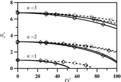
(2) Note that Eq. (2) reveals a very important phenomenon that boundary shears couple with displacements in time derivatives in two perpendicular directions, as underlined, due to the occurrence of rotation. Unlike a non-rotating shaft, in which the boundary shears in two perpendicular directions, said Vy and Vz, are uncoupled and time independent to each other. The coupling terms could be significant at very high rotational speed as to be shown. Solve the boundary value problem of eqs.(1,2) and draw its frequency loci on Figure 2. Figure 2 illustrates the coupling shears effects on the shaft’s natural frequencies with rotational speed, where ω∗n =ωn/ω0 ,
/ω0
Ω
=
Ω∗ and
ω
nis the rotating shaft’s nth natural frequency andω
0is shaft’s first flexural natural frequency at Ω=0. It is noticed that the exact (coupled) solutions have lower natural frequencies. That means the shaft’s critical speeds, intersections with abscissa, are overestimated if the coupling effects were ignored, e.g., around 50%higher for free-free case.
2.2 Transfer Matrix Of An Offset Misalignment
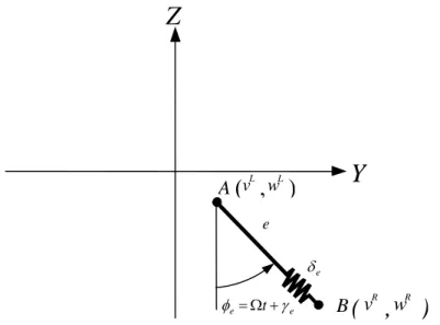
There are two types of shaft misalignment, one is of parallel offset as shown in Figure 3, and the other is of angular offset as shown in Figure 4. In the present studies a flexible coupling is modeled as a translational spring combined with a bending spring.
In between two ends of the coupling, there is a parallel offset as shown in Figure 5.
According to the equilibrium relations, the authors derive the misalignment transfer matrix in the following
1 ,
)
sin( L
B L R e
L L y R
MZ
t K K e
v
Vv
= + + ⋅ Ω +γ φ =φ − (3)w
R 1, )
cos( YL
B L R e
L z
L M
t K K e
w − V − ⋅ Ω + = − ⋅
= γ θ θ (4) The moments, shear forces are continuous, i.e., MR =ML,VR =VL. KL and KB
are linear and bending stiffness of the coupling φe =Ωt+γe, γe is the phase relative to rotor’s reference. Note that the torsional vibration is not considered so that
e
e t γ
φ =Ω + retains all the times. r= e+δe is dynamic offset, δe is linear displacement of the spring. The transfer matrix of misalignment yields to be
{ }
S R =[ ]{ } { }
M S L+ C (5) where[ ] [ ] [ ] { } [ ] [ ] { }
{ } { }
⎥⎥⎥
⎦
⎤
⎢⎢
⎢
⎣
⎡
=
×
×
×
× ×
× ×
×
1 0
0
0 0
8 1 8
1
1 8 8
4 8 8 3 8
1 8 8 2 8 8 1 8
M M
M M
M (6)
is the defined coupling transfer matrix, and C T
C
C} {{ }{ }1}
{ 17×1= 1 2 (7)
is the defined misalignment vector with
{ } { }
{ } { }
⎪⎩
⎪⎨
⎧
−
=
=
0 0 0 cos 0 0 0 cos
0 0 0 sin 0 0 0 sin
2 1
e e
e e
e e
C
e e
C
γ γ
γ
γ (8)
Equation (5) is, for the first time derived, the transfer matrix of a coupling with parallel misalignment.
[ ]
M [14], similar to the others [15], a matrix links the left and right states, and{ }
C is the misalignment vector that plays a role like an exciting force in an unbalanced rotor. It will be seen that after multiplication to its right matrices, all components right to the misalignment contribute to the excitation. That means after the misalignment the driven shaft plays as a whole the excitation to the rotor. If there is no misalignment (e=0), this vector vanishes and Eq. (5) simply represents a transfer matrix of a coupling.2.3 Local Flexibility Matrix Due To Transverse Crack
In the present work, a general dynamic model for rotor-bearing system with a cracked shaft, rotating at constant speed is introduced. Dimarogonas and Paipetis [3]
employed the Castigliano’s theorem and formulated a 5×5 local flexibility matrix for a rectangular beam containing a transverse crack of uniform depth. According to their investigation, the other terms could be neglected provided the bending moment was the dominant term. The rotors with a transverse open crack as shown in Figure 6.A section of a shaft containing a transverse crack of depth a. The flexibility coefficients of crack depth (Cr =a/R) for a circular shaft in two perpendicular directions, as shown in Figure7, were in a dimensionless form [21]
∫ ∫
− ⎟⎠
⎜ ⎞
⎝
⎟ ⎛
⎠
⎜ ⎞
⎝
⎟ ⎛
⎠
⎜ ⎞
⎝
⎟ ⎛
⎠
⎜ ⎞
⎝
⎛
⎥⎥
⎦
⎤
⎢⎢
⎣
⎡ ⎟
⎠
⎜ ⎞
⎝
−⎛
=
= −
R b
R b
R
d R d R F h
R R EC
C R
η
ξ η η η ξ
ν π
0
2 2 2
2 55 3 55
, 1
32
1 (9)
∫ ∫
⎜⎝⎛ ⎟⎠⎞ ⎜⎝⎛ ⎟⎠⎞ ⎜⎝⎛ ⎟⎠⎞ ⎜⎝⎛ ⎟⎠⎞ ⎜⎝⎛ ⎟⎠⎞=
= −
R
b R
d R d R F h
R R E C
C R
0 0
2 1 2 2 44
3 44
, 32
1
η
ξ η η η ξ
ν π
(10)
in which h=2
R
2 −ξ
2 is the local height of a strip , R is the radius of the shaft , 2b is the crack width , and F2( )a h and F1( )a h denote the geometrical parameters,( )
[
( )]
( a h)h a h
a a
h h a
F cos 2
2 sin 1 199 . 0 923 . 0 tan 2
2 4
2
π
π π
π
−
⎟ +
⎠
⎜ ⎞
⎝
= ⎛ (11)
( ) ( )
[
( )]
( a h)
h a h
a h
a a
h h a
F cos 2
2 sin 1 37 . 0 02
. 2 752 . 0 tan 2
2 3
1
π
π π
π
− +
⎟ +
⎠
⎜ ⎞
⎝
= ⎛ (12)
Applying Hamiliton’s principle, the equations of motion for a rotating shaft in the rotating coordinates are
⎪⎩
⎪⎨
⎧
= Ω
− Ω + +
′′′
′
= Ω
− Ω
−
′′′+
′
0 2
0 2
2 2
w A v A w A w EI
v A w A v A v
EI
yy zz
ρ ρ
ρ
ρ ρ
ρ
&
&&
&
&&
(13)
The crack matrix is represented by means of a rotating shaft matrix that contains the additional flexibilities (introduced) due to existence of the crack. According to the equilibrium relations and compatibility conditions due to the local flexibility, the crack matrix ][
T
c is given from [20]44
L L
R
MZ
C ⋅ +
=
φ
φ
,θ
R =θ
L +C
55⋅M
YL (14)The displacements, shear forces and moments, are continuous, i.e.,
L
R v
v = , wR =wL,VR =VL, MR =ML. WhereC44,
C is referred to Eqn (9) and (10).
552.4 Overall Transfer Matrix Of Rotor System
Assume a typical misaligned rotor system where there is a misaligned coupling between the kth and k+1th elements, as Figure 1 shows. The overall transfer matrix containing unbalanced disk and misaligned shaft is derived to be
{ }
S nR =[Tu]{S}1L+[Tm]{C} (15)where {S}1L represents the left state of unit 1,
{ }
S nRis the right state of unit n, and⎪⎩
⎪⎨
⎧
⋅⋅
⋅⋅
⋅⋅
⋅
=
⋅⋅
⋅⋅
⋅⋅
⋅
⋅⋅
⋅⋅
⋅⋅
⋅
=
+
−
−
− +
−
1 2
1
1 2 1
1 1
] [ ]
[ ] [ ] [ ] [
] [ ] [ ]
[ ] ][
[ ] [ ]
[ ] [ ] [
k n
n n m
k k k
n n u
T T
T T T
T T T
T M T T
T
T (16)
Note that
[ ]
T idenotes the ith element transfer matrix, that could be shaft, bearing, or disk. [Tu]is the overall transfer matrix yielded by the multiplication of all transfer matrices and [Tm]is the multiplication of the transfer matrices to the right of misalignment, i.e., from k+1th to the nth. Substituting the boundary conditions, a 9 × 9 matrix will yield1 4 4
1 4 L 8
1 8 8
1
1 8 8
8 1 u
8 {C }
} 0 {
] m [ 1
} S { 1 }
0 {
} u { ] T [ 1
} 0 {
×
×
× ×
×
×
× × ⋅ ′
⎭⎬
⎫
⎩⎨ +⎧
⎭⎬
⎫
⎩⎨
⎧ ′
⎥⎦
⎢ ⎤
⎣
⎡ ′
⎭=
⎬⎫
⎩⎨
⎧
(17)
with the condensed misalignment vector
T e e
e
e e e e
e
C } { sin , sin , cos , cos }
{ ′ 4×1 = − γ − γ − γ γ (18)
where elements of [Tu]′,{ u} and [ m]are the degeneration of[Tu]and [Tm]matrices.
Furthermore, simplify the above equation and rearrange, one can write it as
⎭⎬
⎫
⎩⎨
⎧− ⋅ ′
⎭=
⎬⎫
⎩⎨
⎧ ′
⎥⎦
⎢ ⎤
⎣
⎡ ′ × × ×
×
×
×
1 } { ] [ 1
} { 1 }
0 {
} { ]
[ 81 8 4 41
8 1
1 8 8
8 u S m C
Tu L
(19) or
1 4 4 8 1 8 1
8 8
8 { } { } [ ] { }
]
[Tu ′× × S′ L× =− u × − m × ⋅ C′ × (20)
There are two effects in the Eq. (15). On the right side, the first term is the unbalanced excitation and the second term is the misalignment excitation. Provided the misalignment is zero (e = 0), Eq. (15) yields to an unbalanced response analysis. If the coupling stiffness KB and KL approach infinite,
[ ]
M matrix becomes an identity matrix, representing a rigid coupling.3. Numerical Results And Discussion
The rotor system consists of three bearings, four rigid disks, and seven-section flexible shaft as Figure 8 shows. The flexibility modulus is E=20.69×10¹⁰
N/m
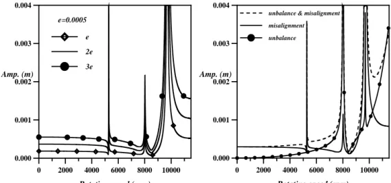
2, density is ρ =8193.0kg/m3, and the three bearings are of the same constants in Y and Z direction ( Kyy= Kzz=1.75×10⁸N-m). Figure 9 shows the FRF of the rotor with three
different offset values. Cross-referencing Figure 9 and Eqs. (7,8) it is realized that the coupling stiffness affects the rotor’s critical speeds but the offset performs just like an excitation. As seen, resonance occurs at the same critical speeds and the FRF amplitude is proportional to the offset value.The mutual effects of shaft misalignment and disk unbalance are calculated and as shown in Figure10. From the curves, it is seen the misalignment predominates rather than unbalance. Figure 11 shows the whirling orbits of the system with merely shaft offset (solid) and combine effects of unbalance and offset (dashed). Three plots correspond to (a) Ω<Ωcr1 (b) Ωcr1<Ω<Ωcr2(c) Ω <cr2 Ω<Ωcr3. From Figure 11, it is seen that at lower rotation speed, shaft misalignment predominates. The unbalance only slightly changes the orbit orientation. With the increase of rotational speeds, due to centrifugal force generated by disk unbalance, the orbit change significantly in both orientation and magnitude.
4. Conclusions
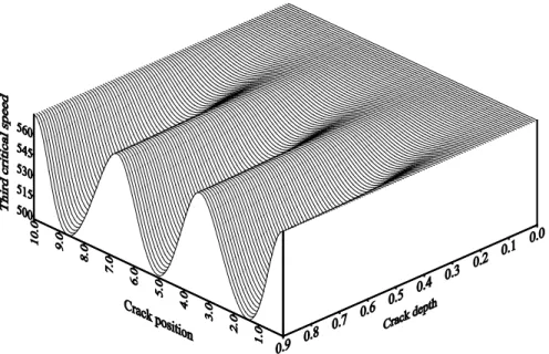
The numerical results indicate that natural frequencies varied with the shaft’s crack location and depth, and the critical speeds of system would decrease due to existence of crack. A point of interest to the authors is how the shaft’s rotation speed affects the natural frequencies of the system. Figures 12 show the variation of the first few system frequencies with the rotation speed for various crack depth. These curves are similar to those often seen in rotor systems; each natural frequency splits into two branches, one increasing and one decreasing, as the rotation speed increase from zero. The lower branches eventually intersect the abscissa at what are customarily referred to as critical speeds of the system, which belong to the divergent type of instability. After the critical speeds, the lower curves “reflect ’’ and ultimately merge with the upper branch. In the vicinity of merging point, the sensitivity of ω to Ω approaches infinity, so it is very difficult to get the numerical solutions. That is why the curves showed scattering in these regions. Figure 13 showed the third critical speed. It can be seen from the figure that the critical speeds were significantly influenced by positions and depth. In general, the critical speeds decreased more as the crack approached to the middle position of the shaft except passing through some particular points.
The present research derived the transfer matrix for flexible coupling with parallel misalignment. The investigation reveals that coupling stiffness affects the critical speeds and the offset misalignment plays as an excitation. During the derivation of a rotating shaft transfer matrix, the authors found that the boundary shears in two perpendicular directions were coupled together due to rotation. The coupling shears affected the most as the shaft was free at both ends. It might reduce the shaft’s first critical speed up to 50%. The derivation of TMM and numerical results revealed that misalignment induced lateral response of the same frequency as rotational speed (1×) and that is unlike most of the researches where multiple integers (n×) components were found. We believe that the reason of n× components disappearing in our derivation is due to the coupling’s torsional vibration was not considered. Since the coupling will transmit torque as well and if the torsional flexibility of the coupling is taken into account the driven shaft will fluctuate torsionally and it causes non-constant rotation. The non-constant speed in conjunction with the misalignment and unbalance will consequently generate n×
frequencies of cyclic forces and moments on lateral vibration. The combined effects of disk unbalance and shaft misalignment showed that shaft misalignment imposed much greater effect than the disk unbalance at most of rotational speeds. That means the shaft misalignment usually plays a dominating role. The effect of disk unbalance will become of the same significance as the rotor is at very high rotational speeds. The dynamic characteristics of the rotating shaft were significantly influenced by the locations and depth of the crack. The critical speeds decreased rapidly when the crack approached to the middleposition of the rotating shaft. However, if the crack happened at inflection points of a specific mode, the critical speeds scarcely changed.
References
[1] Nelson H.D. and McVaugh J.M., “The dynamics of rotor bearing systems using finite elements”, ASME J. Eng. for Industry, 593-600(1976)
[2] Ο&& zgu&&ven H.N., “On the critical speed of continuous shaft-disk systems”, ASME J. Vibr. Acoust., Stress, and Reliability in Design,106, 59-61(1984)
[3] Gu J., “An improved transfer matrix-direct integration method for rotor dynamics”, ASME J. Vibr., Acoust., Stress, and Reliability in Design, 108, 182-188(1986)
[4] Prohl M.A., “A general method for critical speeds of flexible rotors”, J. Applied Mechanics, 67, 142-148(1945)
[5] Lund J.W. and Orcutt F.K., “Calculations and experiments on the unbalance response of a flexible rotor”, ASME J. Eng. for Industry, 89, 785-796( 1967)
[6] Chao S.W. and Huang S.C., “On the flexural vibrations of shaft-disk systems using a modified transfer matrix method”, Proceedings of the 6th National Conference of the CSME, 1607-1618 (1989)
[7] Rieger N.F. and Zhou S., “Development and verification of transfer matrix unbalance response procedure for three-level rotor-foundation systems”, ASME J. Vibr. Acoust.,120(1), 240-251 (1998) [8] Zu J.W. and Ji Z., “An improved transfer matrix method for steady-state analysis of nonlinear rotor
bearing systems”, ASME J. Eng. Gas Turbines Power, 124(1), 303-310(2002)
[9] Dewell D.L. and Mitchell L.D., “Detection of a misaligned disk coupling using spectrum analysis”, ASME J. Vibr., Acoustics, Stress, and Reliability in Design, 106, 9-16(1984)
[10] Xu M. and Marangoni R.D., “Vibration analysis of a motor-flexible coupling-rotor system subject to misalignment and unbalance, PartΙ: Theoretical model and Analysis”, J. Sound Vib., 185(3), 663-679(1994)
[11] Xu M. and Marangoni R.D., “Vibration analysis of a motor-flexible coupling-rotor system subject to misalignment and unbalance, Part II: Experimental Validation”, J. Sound Vib.,176(8), 681-691( 1994)
[12] Lee Y.S. and Lee C.W., “Modeling and vibration analysis of misaligned rotor-bearing system”, J.
Sound Vib.,224(1) , 17-32( 1999)
[13] Al-Hussain K.M.and Redmond I., “Dynamic response of two rotors connected by rigid mechanical coupling with parallel misalignment”, J. Sound Vib., 249(2) , 483-498(2002)
[14] Gasch R., “Dynamic behavior of a simple rotor with a cross-section crack,” I Mech E Conference Publication, Vibration in Rotating Machinery, Paper No C178/76(1976)
[15] Dimarogonas A. D. and Paipetis, S. A., 1983, “Analytical method in rotor dynamics,” Appl. Sci.
London.
[16] Huang S. C., Huang, Y. M., and Shieh, S. M., “Vibration and stability of a rotating shaft containing a transverse crack,” J. Sound Vib., 162(3), 387-401(1993)
[17] Wu M. C. and Huang, S. C., “In-plane vibration and crack detection of shaft-disk rotors containing a transverse crack,” ASME J. Vibration and Acoustics, 120(2), 551 - 556(1998)
[18] Prabhakar S. Sekher, A. S. and Mohanty, A. R., “Crack versus coupling,misalignment in a transient rotor system,” J. Sound Vib., 256(4), 773-786(2002)
[19] Dong G. M., Chen J. and Zuo J., “Paramater identification of a rotor with an open crack”, European J. of Mechanics A/Solids, 23, 325-333 (2003)
[20] Itahak G. and Cody C., “Crack detection in a rotor dynamic system by vibration monitoring-partΙ:
Analysis”, ASME J. Eng. Gas Turbines and Power, 127(1), 425-436 (2005)
[21] Dimarogonas A. D. and Papadopoulos, C. A., 1983, “Vibration of cracked shaft in bending”, J.
Sound Vib.,91(4) , 583-593( 1989)
[22] Tsai C.Y., “Transfer matrix method to misalign vibration analysis in rotor systems”, Master Thesis, Department of Mechanical Engineering, National Taiwan University of Science and Technology (1997)
[23] Rao J.S., Rotor Dynamics. Wiley Eastern Limited (1983)
... n-1 n 2 3
1 ...
M k + 1 k
Figure 1 - Schematic diagram of a misaligned rotor in transfer matrix method
∗
ω
nΩ*
0 20 40 60 80 100
0 2 4 6 8
Coupled Uncoupled
Forward modes Backward modes
n =1 n =3
n =2
Figure 2(a) – Natural frequencies of a rotating shaft with free-free boundary
r
A B
Z
Y
X
Figure 3 -
Rotors with parallel misalignment
Z
Y
β
X
Figure 4 -
Rotors with angular misalignment
0 20 40 60 80 100
0 2 4 6 8
Ω*
∗
ω
n n =2n =1 n =3
Figure 2 (b)– Natural frequencies of a rotating shaft with simple-free boundary
Figure 8 - Example of a misaligned
rotor
: Unbalanced mass1 2 3 4 5 6 7 8 9 10
12 13 14 11
A
B
Z
)
Y
, (vL wL
( v
R, w
R)
A
B
e
e t γ
φ =Ω + e
δe
Figure 5 - Displacement of misalignment
Z X
Y
Figure 6 - Shaft with a transverse crack Figure7 –Cracked section of the shaft
Z
Y
(b) Ωcr1 < Ω < Ωcr2 (c) 2 <
Ω
cr < ΩΩ
cr3Figure 11 - Whirling orbits at different rotational speed due to mutual effect of shaft misalignment and disk unbalance
-0.003 -0.001 0.001 0.003
v (m) -0.003
-0.001 0.001 0.003
w (m)
-0.003 -0.001 0.001 0.003
v (m) -0.003
-0.001 0.001 0.003
w (m) (a) Ω < Ωcr1
-0.003 -0.001 0.001 0.003
v (m) -0.003
-0.001 0.001 0.003
w (m)
B A
Figure 9 - FRF due to misalignment
0 2000 4000 6000 8000 10000 Rotating speed (rpm) 0.000
0.001 0.002 0.003 0.004
Amp. (m)
e=0.0005 e 2e 3e
Figure 10 - FRF due to misalignment and unbalance
0 2000 4000 6000 8000 10000 Rotating speed (rpm) 0.000
0.001 0.002 0.003 0.004
Amp. (m)
unbalance & misalignment misalignment
unbalance
Ω (rad/sec)
ω (rad/sec)
Figure 12 -
Variation of natural frequencies with rotation speed
0 200 400 600 800 1000 1200 1400
0 200 400 600 800 1000 1200 1400
Cr : 0.3 Cr : 0.5
uncrack
Figure 13 -