行政院國家科學委員會專題研究計畫 成果報告
氣壓手臂結合影像視覺在空間軌跡控制及互動性與自動化 應用之整合研究
研究成果報告(精簡版)
計 畫 類 別 : 個別型
計 畫 編 號 : NSC 96-2221-E-011-103-
執 行 期 間 : 96 年 08 月 01 日至 97 年 07 月 31 日 執 行 單 位 : 國立臺灣科技大學機械工程系
計 畫 主 持 人 : 王英才
處 理 方 式 : 本計畫可公開查詢
中 華 民 國 97 年 10 月 21 日
行政院國家科學委員會補助專題研究計畫
x
成 果 報 告□期中進度報告
氣壓手臂結合影像視覺在空間軌跡控制及互動性與自動化應用之整合研究
Pneumatic Arms Integrated with Photo Vision for Multi-Degree Trajectory Control, Interactive and Automation Applications
計畫類別:X 個別型計畫 □ 整合型計畫 計畫編號:NSC-96-2221-E-011-103 執行期間:96 年 8 月 1 日至 97 年 7 月 31 日
計畫主持人:王英才 共同主持人:
計畫參與人員:
成果報告類型(依經費核定清單規定繳交):□精簡報告 X 完整報告
本成果報告包括以下應繳交之附件:
□赴國外出差或研習心得報告一份
□赴大陸地區出差或研習心得報告一份
□出席國際學術會議心得報告及發表之論文各一份
□國際合作研究計畫國外研究報告書一份
處理方式:除產學合作研究計畫、提升產業技術及人才培育研究計畫、
列管計畫及下列情形者外,得立即公開查詢
□涉及專利或其他智慧財產權,□一年□二年後可公開查詢
執行單位:
中 華 民 國 97 年 10 月 20 日
摘要
本計劃的研究內容是發展利用影像視覺進行軌跡控制之多軸氣壓手臂,進而研究氣壓手 臂間的互動性與在自動化整合應用之研究。第一年的研究重點在設計一利用影像視覺進 行軌跡量測之 2D 氣壓手臂,由氣壓組件、控制器、CCD 等對 2D 氣壓手臂特性到軌跡 控制的影響等研究,詳細的研究項目可分成三大部分:(1)撓性氣壓缸、旋轉氣壓缸等不 同氣壓手臂的特性差異,利用相同控制器討論其軌跡追蹤控制的特性與精度;(2)滑動模 糊、自組織模糊、自組織滑動模糊等不同控制器在 2D 氣壓手臂的控制特性,實驗結果及 暫態與穩態特性分析;(3)非接觸式 CCD 影像視覺與傳統接觸式感測器應用在 2D 氣壓 手臂的位移量測以及其應用在軌跡控制的特性,分析 CCD 影像視覺取代傳統感測器在 2D 氣壓手臂應用的可行性。由於這些研究內容與成果都已經申請發表於國際期刊,第(1) 項已發表,第(2)項被接受發表,第(3)項正在申請發表中,因此本年度的研究結案報告 以這三份論文內容呈報。
1. Comparative Studies of the Set Up of Two-Dimensional Pneumatic Arm Systems by Muscle and Rotational Actuators. [發表於 Proceedings of the Institution of Mechanical Engineers, Part I: Journal of Systems and Control Engineering, V. 221, N. 5, P743~P748, 2007]
2. Fuzzy Control of a 2D Pneumatic Muscle Actuator’s Arm. [被接受發表於 Measurement and Control, 預定出刊日期 Dec. 2008]
3. A CCD-Based 2D Pneumatic Arm Control System. [申請發表中]
關鍵字: 撓性氣壓缸、旋轉氣壓缸、2D 氣壓手臂、CCD 影像視覺、自組織模糊控制、
滑動模糊控制、自組織滑動模糊控制
Abstract
This long-term project is mainly to design and setup photo vision based multi-degree
pneumatic arms and their automation applications. In the first year, it focuses to setup a photo vision based 2D pneumatic arms. Its research works cover the component design, controller design and CCD measuring process, and then to study the influences from their trajectory tracking performances. It can be divided into three main subjects: (1) From the viewpoint of pneumatic components, it is to study dynamic characteristics of 2D pneumatic arms setup by muscle actuators and rotational actuators respectively. Then, it uses the same controller to compare their trajectory tracking performance and control accuracy. (2) From the viewpoint of controllers, it develops the sliding-mode fuzzy controller, self-organizing fuzzy controller and self-organizing sliding-mode fuzzy controller for 2D pneumatic arm’s trajectory tracking control. Then, it compares and justifies their transient and steady state performances via the variety experiments. (3) From the viewpoint of 2D displacement measuring process, both CCD and classical contacted sensors are installed to attain the 2D displacement feedback signal. It compares the trajectory tracking performances of CCD-based and encoder-based 2D pneumatic arm control systems, and then explains that CCD is an option to replace encoders in the 2D pneumatic arm control system. Since some of these subjects and results have been published and/or submitted for publications in the international journals, the final report would be submitted based on these three journal papers.
1. Comparative Studies of the Set Up of Two-Dimensional Pneumatic Arm Systems by Muscle and Rotational Actuators. [Proceedings of the Institution of Mechanical Engineers, Part I:
Journal of Systems and Control Engineering, V. 221, N. 5, P743~P748, 2007]
2. Fuzzy Control of a 2D Pneumatic Muscle Actuator’s Arm. [accepted by Measurement and Control, will appear in Dec. 2008]
3. A CCD-Based 2D Pneumatic Arm Control System. [submitted for publications]
Keywords: muscle actuator, rotational actuator, 2D pneumatic arm, CCD photo vision, self-organizing fuzzy control, sliding-mode fuzzy control, self-organizing sliding-mode fuzzy control
II
目錄
1.中文摘要………...I 2.英文摘要………..II 3.目錄………...III 4. Comparative Studies of the Set Up of Two-Dimensional Pneumatic Arm Systems by Muscle
and Rotational Actuators.………… ……….1
5. Fuzzy Control of a 2D Pneumatic Muscle Actuator’s Arm………...7
6. A CCD-Based 2D Pneumatic Arm Control System.……… …..….17
7. 計畫成果自評...33
8. 可供推廣之研發成果資料表...34
1
3
5
Fuzzy Control of a 2D Pneumatic Muscle Actuator’s Arm
YingT. WANG1 R-H WONG1,2 C-W YU1 and W-C HUANG1
1Department of Mechanical Engineering,
National Taiwan University of Science and Technology, 43, Keelung Rd. Sec.4, Taipei, Taiwan 106, R.O.C
2Department of mechanical Engineering, Hwa Hsia Institute of Technology,
111 Gong Jhuan Rd., Chung Ho, Taipei, Taiwan 235, R.O.C
Abstract
Pneumatic muscle actuators are newly developed actuators in rotational, non-aligned and specified applications. In this paper, pneumatic muscle actuators are used to set up a two-dimensional pneumatic arm to simulate the excavator’s motion. Fuzzy control algorithms are typically applied in pneumatic control systems owing to their non-linearities and ill-defined mathematical models. Two fuzzy controllers, which include the sliding mode fuzzy controller and self-organizing fuzzy controller, are comparatively implemented in this 2D pneumatic arm control system. The present paper provides the comparisons of trajectory tracking performances and adaptations of these two fuzzy controllers via a variety of trajectory tracking experiments.
Keywords: 2D pneumatic arm, muscle actuator, self organizing fuzzy controller, sliding mode fuzzy controller
1 INTRODUCTION
Pneumatic muscle actuators are developed to take the place of conventional pneumatic linear actuators in applications of rotational, non-aligned and complicated mechanisms. In
7
industrial applications, 2D mechanical arms are used widely because of their simplification and efficiency [1~3]. In this paper, pneumatic muscle actuators driven by pressure type servo-valves are used to setup a 2D pneumatic arm control system to simulate the motion of an excavator [1].
The muscle actuator consists of a cylindrical rubber bladder. Its relaxation and contraction is actuated via the pressure change of a rubber chamber. In order to compare this with the traditional linear actuator, the muscle actuator has high power/weight and power/volume ratios [4, 5]. Thus the muscle actuator is widely implemented in high payload, rehabilitation engineering and therapy robots. Due to the compressibility and non-linear elasticity of the rubber bladder, the muscle actuator is a non-linear component.
This 2D pneumatic arm control system is a non-linear two-input two-output (TITO) system.
Without the detailed model, fuzzy control algorithms have been found to be effective in dealing with non-linear, complicated and ill-defined systems. This paper proposes to implement the sliding-mode fuzzy controller and the self-learning fuzzy controller for a 2D pneumatic arm’s trajectory tracking control. In the sliding mode fuzzy controller, the fuzzy sliding surface is designed to reduce 2-dimensional fuzzy rules into 1-dimensional fuzzy rules and thus can simplify the learning processes of fuzzy rules’ optimization. The self-organizing fuzzy controller has a self-learning mechanism to modify fuzzy rules online.
Then, the present paper can compare their trajectory tracking performances and evaluate their adaptations by a variety trajectory tracking experiments,.
2 SYSTEM DESCRIPTIONS
The 2D pneumatic arm control system set up by muscle actuators is shown in Figure 1.
M1 and M2 are muscle actuators and their specifications are 20φ ×305mm and mm
204
20φ × respectively. They are driven by pressure type servo valves (MPPES-3-1/8- 010 of Festo Co.). The contraction range of muscle actuator is -3 ~ 20%. The work space of this 2D pneumatic arm is limited due to the limitations of contraction range. θ and 1
θ are angular displacements measured by encoders 2 E1 and E2 . The encoder’s resolution is 2000 pulses/cycle. The first arm’s length l1 is 440mm and its weight including the encoder is 2.5kg. The second arm’s length l2 is 408mm and the weight is
0.9kg. The loading is 4kg. The resolution of D/A port is 12bits. The personal computer (PC) is a 80586 microcomputer system. The control program is developed by Turbo C++.
3 CONTROL SCHEMES
A 2D pneumatic arm shown in Fig. 1 is used to simulate the excavator’s motion. Through the kinetic transformation, the relationships between measured angular displacements (θ1,θ2) and absolute position (X, Y) of loading are:
) cos(
cos 1 2 1 2
1 θ − θ +θ
=l l
X (1) )
sin(
sin 1 2 1 2
1 θ − θ +θ
=l l
Y (2) and, their inversed kinetic transformations are:
cos ) ( sin
tan ) ( tan
2 2 1
2 1 2
1
1 θ
θ θ
l l
l X
Y
− +
= − − (3)
2 ) (
cos
2 1
2 2 2 1 2 2 1
2 ll
l l Y
X + − −
= −
θ (4)
9
Here, θ1 and θ2 could be individually driven by each actuator. This 2D pneumatic arm
control system is a non-coupled TITO system, and the controller can be designed for each sub-system individually. The functional block diagram of control structure is shown as Fig.
2.
In comparison with other control algorithms, the fuzzy control approach has been found to be an effective algorithm to deal with complicated, ill-defined and poor mathematically modeled dynamical processes. In general, the fuzzy rule base is 2-dimensional which depends on system variables (e, ce). Therefore, to optimize a 2-dimensional fuzzy rule table requires a lot of effort.
The configuration of the sliding-mode fuzzy controller (SMFC) [6] is shown as Fig. 3.
The sliding surface is proposed to simplify and reduce 2-dimensional fuzzy rules into 1-dimensional fuzzy rules. It is described as
s=α⋅e+ce (5) where α is a positive constant. The gains G and s G are used to normalize between u
system variables and the universal of fuzzy sets. The fuzzy sets are finely divided into 13 linguistic fuzzy subsets. Fuzzification is adopted the triangular-type membership function to obtain linguistic variables. The fuzzy inference is based on the Max-Min product composition and is used to operate fuzzy control rules. Then, the height method is used to
defuzzify the fuzzy sets to attain the control signal.
For the self-organizing fuzzy controller (SOFC) [7], its detailed configuration is shown as Fig. 4. To reduce efforts in learning fuzzy rules, SOFC includes a self-learning mechanism to modify the 2-dimensional 7×7 rule table online. In the self-learning mechanism, the input reinforcement is defined by corrections to compensate error and error change. Thus, the linguistic approach rule base can be modified as
)]
( ) ( ) 1 [(
) ( )
1
( e k ce k
M w r w k RULES k
RULES + = + ei cei −ζ +ζ 0≤ζ ≤1 (6) Here, r is the learning rate to compensate the output error. M is a ratio to simulate the relationship between input signal of servo-valve and angular displacement output. ζ is
the weighting factor of corrections for error and error change. w is the intensity of excitation modules and is obtained by the interpolation technique.
4 EXPERIMENTAL RESULTS
In the present paper, this 2D pneumatic arm control system is applied for point-point and variety trajectory tracking applications. To cover different trajectory slopes at initial and final times, the commands include step, ramp and parabolic functions. The command (X ,d Y ) is from (0, 0) to (100,100) mm, and the working time is 4 seconds. d
Through trial and error, parameters of SMFC are properly chosen as Gs =0.6, Gu =10
and α =0.6. SMFC’s 1-dimensional fuzzy rules are 1×13 and these fixed fuzzy rules
11
NVB=-1, NB=-0.8, NM=-0.5, NSM=-0.3, NS=-0.2, NVS=-0.1, ZO=0, PVS=0.1, PS=0.2, NSM=0.3, NM=0.5, NB=0.8 and NVB=1 are properly chosen to have low resolution at large error and high resolution at small error. Parameters of SOFC are Ge =Gce =1,
=10
Gu , r/M =0.5 and ξ =0.5.
To evaluate the control accuracy, the absolute position error is defined as
2
2 ( ( ) ( ))
)) ( ) ( ( )
(k X k X k Y k Y k
e = − d + − d (7) and, the average tracking error is
N k e e
N
k
∑=
= 1 ) (
(8)
Here, the sampling time is 0.01second and thus N=400. The following experiments are included to evaluate control performances of SMFC with SOFC. Case 1 is a point-point control experiment and its command is a step function. Fig. 5 is the time response of Case 1 without loading. In general, the effects of the rubber bladder’s elasticity and pneumatic compressibility would induce the time delay. Time responses indicate that both SMFC and SOFC have similar transient behaviours and both settling times are about 1.5 seconds. In the steady state, SOFC has better convergence and less oscillation. To compare their steady state errors e(k=400), SMFC is 0.96mm and SOFC is 0.32mm, which are summarized in Table 1.
momentum effect, it enhances more time delay and their settling times postpone to 2.0 seconds. Responses of both SMFC and SOFC oscillate slightly in the steady state
process. However, SOFC still has a better steady state accuracy as indicated in Table 1.
SMFC has less adaptation comparing with SOFC due to it’s fixed fuzzy rules.
Case 2 is a straight trajectory tracking control case. Its command is a ramp function.
Figures 7 and 8 display the tracking performances in the X-Y plane. For the ramp input, the time delay effect is degraded. The tracking performance is now improved. Without loading, the average error e of SMFC is 1.53mm, and SOFC is 1.32mm. SMFC of Case 2 with loading has significant oscillations in the tracking process. e of SMFC apparently enlarges to 2.09mm, and its steady state does not converge adequately and its steady state error e(k=400) is up to 1.87mm. Again, SOFC can fit for variety loading and has a better trajectory tracking performance.
Case 3 is a quadratic trajectory tracking control case, and its command is a parabolic function. Figures 9 and 10 are the tracking performances displayed in the X-Y plane. The influence of system delay is tremendously decreased owing to the characteristics of parabolic function. The tracking performance of SOFC perfectly matches the command in Fig. 9. To compare Fig. 9 with Fig. 10, SMFC has significant chatting in the tracking process and enlarges the oscillation while adding the loading, i.e. e is 1.33mm of Case 3
13
without loading and e is enlarged to 1.76mm of Case 3 with loading. In SOFC, the trajectories of both figures have no significant difference, which means SOFC can adapt to variety loading.
5 CONCLUSIONS
In this paper, SOFC and SMFC are applied for the trajectory tracking control of a 2D pneumatic muscle actuator’s arm. Comparisons of their tracking performance lead to following conclusions.
1. A 2D pneumatic arm control system can be easily set up by pneumatic muscle actuators.
Since it is a non-coupled TITO system, SMFC and SOFC can be designed for each sub-system individually and they could be properly implemented for trajectory tracking applications.
2. To compare with the traditional fuzzy control, SMFC can reduce the fuzzy rule base and reduce the effort in the trial and error but its fixed fuzzy rule base has to be adjusted for different cases.
3. The self-learning mechanism of SOFC can adjust fuzzy rules on-line, which skips the fuzzy rule’s learning process in SMFC.
4. Experimental results indicate that SOFC has a better trajectory tracking and steady
state accuracy than SMFC. They also verify the robustness and feasibility of SOFC applied in this 2D pneumatic arm control system.
ACKNOWLEDGEMENT
This work was supported by Festo Co. and National Science Council of ROC under grant NSC96-2221-E011-103.
REFERENCES
1. Tafazoli, S., Salcudean, S.E., Keyvan, H. and Lawrence, P.D. Impedance Control of a Teleoperated Excavator, IEEE Transactions on Control Systems Technology, V.10, N.3, pp.355-367, 2002.
2. Kawashima, K., Nakamura, N., Miyata T. and Kagawa, T. Application of Robots Using Pneumatic Artificial Rubber Muscles for Operating Construction Machines, IEEE/RSJ International Conference on Intelligent Robots and Systems, pp.3384-3389, 2003.
3. Sasaki, T., Miyata, T. and Kawashima, K. Development of Remote Control System of Construction Machinery Using Pneumatic Robot Arm, International Conference on Intelligent Robots and Systems, Sendai, pp.748-753, 2004.
4. Caldwell, D.G., Medrano-Cerda, G.A. and Goodwin, M. Control of Pneumatic Muscle Actuators, IEEE Control Syst. Mag., V.15, N.1, pp.40-48, 1995.
15
5. Chou, C.P. and Hannaford, B. Static and Dynamic Characteristics of McKibben Pneumatic Artificial Muscles, IEEE Robotics and Automation Conf., pp. 281-286, 1994.
6. Hwang, Y.R. and Tomizuka, M. Fuzzy Smoothing Algorithms for Variable Structure Systems. lEEE Transactions on Fuzzy Systems, V.2, N.4, pp277-284, 1994.
7. Wang, Y.T., Lan, C.C. and Chang, M.K. Comparatively Implementations of a 3-Axial Electro-hydraulic Control System, JSME, Int. J., Series C, V.42, N.4, pp.871-876, 1999.
A CCD-Based 2D Pneumatic Arm Control System
Y. T. WANG1 R. H WONG1,2 and J. H. Lo1
1Department of Mechanical Engineering,
National Taiwan University of Science and Technology, 43, Keelung Rd. Sec.4, Taipei, Taiwan 106, R.O.C
2Department of mechanical Engineering, Hwa Hsia Institute of Technology,
111 Gong Jhuan Rd., Chung Ho, Taipei, Taiwan 235, R.O.C
Abstract
This paper proposes a CCD to replace contacted displacement sensors. CCD is used
to capture the photo vision of 2D pneumatic arm and then transform to X-Y coordinates as feedback signal. It focuses to compare the measuring accuracy and control performance of different displacement sensors. Since the displacement measuring process of CCD requires lots of computational time, it implements the self-organizing sliding-mode fuzzy controller to simplify and optimize fuzzy rules and to reduce the computer load. The present paper simultaneously provides both trajectory tracking performances of CCD-based and encoder-based 2D pneumatic arms via a variety of experiments. And then, evaluate the feasibility of CCD-based 2D pneumatic arm control system.
Keywords: 2D pneumatic arm, CCD, self organizing sliding mode fuzzy controller
1 Intoduction
Pneumatic muscle actuators are developed to take the place of conventional pneumatic linear actuators in applications of rotational, non-aligned and complicated mechanisms. In industrial applications, 2D mechanical arms are used widely because of their simplification
17
and efficiency [1,2]. In this paper, pneumatic muscle actuators driven by pressure type servo-valves are used to setup a 2D pneumatic arm control system to simulate the motion of an excavator.
Instead of the contacted displacement sensors, this paper implements the non-contacted CCD to capture the planer photo vision of pneumatic arm and transforms into two-dimensional displacement signal [3,4]. Both encoders and CCD are installed in this 2D pneumatic arm control system and their two-dimensional displacement can be simultaneously recorded for comparisons. It thus can study the measuring accuracy of CCD signal and evaluate the control performance based on CCD due to the photo vision two-dimensional displacement transformation.
This 2D pneumatic arm is a non-linear control system. Without the detailed model, fuzzy control algorithms have been found to be effective in dealing with non-linear, complicated and ill-defined systems. The sliding-mode fuzzy controller and the self-learning fuzzy controller have been widely applied for pneumatic control systems [5,6].
To integrate the sliding-mode and self-learning fuzzy controllers, this paper proposes the self-organizing sliding-mode fuzzy controller [7] for the trajectory tracking control of 2D pneumatic arm. The sliding surface function is to reduce the two-dimensional into one-dimensional system variables. The one-dimensional self-learning mechanism provides the optimized fuzzy rules online. So, the present paper can compare the trajectory tracking performances of both CCD-based and encoder-based pneumatic arms via variety trajectory tracking experiments. And, it can evaluate the feasibility of replacing classical contacted sensors by the non-contacted CCD in the 2D pneumatic arm control system.
2 System Descriptions
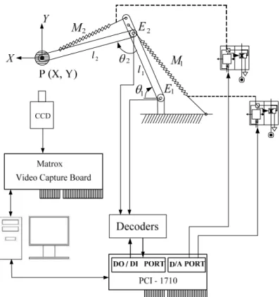
The 2D pneumatic arm control system is shown in Fig. 1. M1 and M2 are muscle
actuators and their specifications are 20φ ×305mm and 20φ ×204mm respectively. They are driven by pressure type servo valves FESTO MPPES-3-1/8-010. The contraction range of muscle actuator is -3 ~ 20%. The work space of this 2D pneumatic arm is limited due to the limitations of contraction range. The first arm’s length l1 is 440mm and its weight including the encoder is 2.5kg. The second arm’s length l2 is 408mm and the
weight is 0.9kg. The loading is 4kg.
Both CCD and encoders are installed to measure the two-dimensional displacement signal. θ and 1 θ are angular displacements measured by encoders 2 E1 and E2 which
resolutions are 2000pulses/cycle. The CCD camera is SONY LV-75 which is to capture the photo vision of X-Y plane. For a fixed CCD location, its photo vision focuses on 219×164mm and its resolution is 640×480pixels. The scaling rate is 59.94Hz. The video capture board is a photo vision decoder to transfer the photo vision signal into X-Y coordinate and determine the 2D pneumatic arm’s location. The resolution of D/A port is 12bits. The personal computer (PC) is a 80586 microcomputer system. The control program is developed by Turbo C++.
3 Control Schemes
19
A 2D pneumatic arm control system shown in Fig. 1 is used to simulate the excavator’s motion. Fig. 2 and Fig. 3 are functional block diagrams of control structures using CCD and encoders respectively. The kinetic transformation is the relationship between angular displacements (θ ,1 θ ) and absolute position (X, Y) of loading. 2
) cos(
cos 1 2 1 2
1 θ − θ +θ
=l l
X (1) )
sin(
sin 1 2 1 2
1 θ − θ +θ
=l l
Y (2) And, the inversed kinetic transformation are:
cos ) ( sin
tan ) ( tan
2 2 1
2 2 1 1
1 θ
θ θ
l l
l X
Y
− +
= − − (3)
2 ) (
cos
2 1
2 2 2 1 2 2 1
2 ll
l l Y
X + − −
= −
θ (4)
This 2D pneumatic arm control system is a non-coupled two-inputs two-outputs system.
θ and 1 θ could be individually driven by 2 M1 and M2 muscle actuators respectively.
And thus, the controller can be designed for each sub-system individually.
In comparison with other control algorithms, the fuzzy control approach has been found to be an effective algorithm to deal with complicated, ill-defined and poor mathematically modeled dynamical process. In general, the fuzzy rule base is two-dimensional which depends on system variables ( e , e& ). To optimize a two-dimensional fuzzy rule table requires a lot of effort.
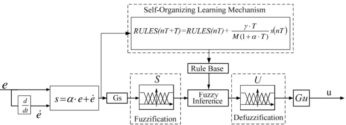
The configuration of the self-organizing sliding-mode fuzzy controller (SOSMFC) is
shown as Fig. 4. The sliding surface is designed to simplify and reduce two-dimensional fuzzy rules into one-dimensional. It is described as
s=α⋅e+e&
where α is a positive constant. The gains G and s G are used to normalize between u
system variables and the universal of fuzzy sets. The fuzzy sets are finely divided into 13 linguistic fuzzy subsets. Fuzzification is adopted the triangular-type membership function to obtain linguistic variables. The fuzzy inference is based on the Max-Min product composition and is used to operate fuzzy control rules. The height method is used to defuzzify the fuzzy sets to attain the control signal. In the self-organizing learning
mechanism, the linguistic approach rule base can be modified as
( )nT T s
M nT T RULES T
nT
RULES ⋅
⋅ + + ⋅
=
+ ) ( ) (1 )
( α
γ (6)
Here, γ is the learning rate to compensate the output error. M is a ratio to simulate the
relationship between input signal of servo-valve and angular displacement output. T is the sampling time.
4 Measuring Error of CCD
In general, the encoder is more accurate and has fast response than CCD. Both (X,Y) signals obtained by encoders and CCD are simultaneously recorded to justify the CCD’s measuring accuracy, and their difference is defined as the measuring error. Table 1 is the static projecting error and measuring error at the working space of experiments in Section
21
5. The projecting error is the portion of measuring error in X or Y coordinates. It indicates that the projecting errors of X and Y coordinates are slightly different. But, the measuring errors are very consistent and the average measuring error is 1.08mm.
Fig. 5 is the dynamic measuring error of point-point control experiment in Section 5.
While the object’s velocity is under 10mm/s, the dynamic measuring error is near to the static measuring error. However, the dynamic measuring error becomes more significant at high objective’s velocity. The measuring error is up to 10mm at 45mm/s. It means the CCD measurement system be reliable at low speed applications.
5 Experimental Results
In the present paper, this 2D pneumatic arm control system is applied for variety trajectory tracking applications including step, ramp and parabolic commands. The sampling frequency of CCD-based system is valid within 28Hz. due to the limitations of photo vision capture process and computational loading. Although the encoder-based system could provide the high sampling frequency, the sampling time of following experiments of both CCD-based and encoder-based systems is fixed at 0.35 sec. in order to ignore the sampling effects. Parameters of SOSMFC are properly chosen as Gs =0.3, Gu =3.8,
=4
α , γ =0.1 and M =1.
To evaluate the control accuracy, the absolute position error is defined as
2
2 ( ( ) ( ))
)) ( ) ( ( )
(k X k X k Y k Y k
e = − d + − d (7) and, the average position error is
N k e e
N
k
∑=
= 1 ) (
(8)
The following experiments are included to compare the control performances of CCD-based and encoder-based systems.
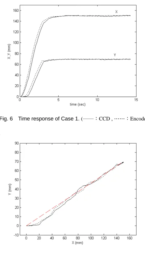
Case 1 is a point-to-point control experiment and its commands are Xd =150 tu( ) and Yd =70 tu( ). Fig. 6 is the time response of Case 1. Due to the characteristics of CCD
measuring process, the time delay of CCD-based system is slightly greater than encoder-based system. Except the slight oscillations in the steady state of CCD-based system, their overall behaviors in time responses are very similar. To compare their steady state performance, the steady state error of CCD-based system is 1.06mm and the encoder-based system is 0.92mm, which are summarized in Table 2.
Case 2 is a trajectory tracking control case of a ramp input. Its commands are )
5 ( ) 5 ( 30 ) (
30 − − −
= tu t t u t
Xd and Yd =14tu(t)−14(t−5)u(t−5). Fig. 7 is the trajectory
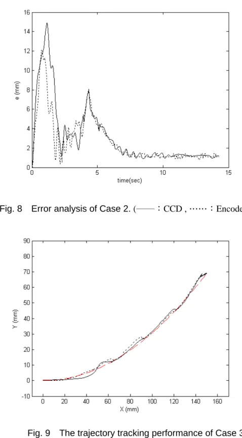
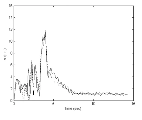
tracking performance of both CCD-based and encoder-based systems. Their performance are similar. Fig. 8 is the error analysis of Case 2. The maximum errors of CCD-based and encoder-based systems are 14.6 and 12.1mm respectively. Except the slight oscillations of CCD-based system, their overall performances have no significant difference. Their
23
average errors and steady state errors are summarized in Table 2. The average error of CCD-based system is 3.23mm, and encoder-based system is 2.75mm. Thus, CCD applied for measuring two-dimensional displacement in the 2D pneumatic arm control system is acceptable.
Case 3 is a quadratic trajectory tracking control case. Its commands are )
5 ( ) 5 ( 30 ) (
30 − − −
= tu t t u t
Xd and Yd =2.8t2u(t)−2.8(t−5)2u(t−5). Fig. 9 is the trajectory
tracking performance. The influence of system delay is tremendously decreased in both systems owing to the characteristics of parabolic function. Except the slight oscillations in the CCD-based system, the tracking performances of both CCD and encoder-based systems match well with the command. Fig 10 is their error analysis. In comparison with Case 2, the maximum errors have been tremendously reduced in the transient process, and the average errors are 2.51 and 2.35mm respectively. Again, the performance of CCD-based system is similar to encoder-based system. It is reasonable to replace encoders by CCD in the trajectory tracking control of 2D pneumatic arm control system.
6 Conclusions
In this paper, it uses non-contacted CCD to replace classical contacted sensors in the 2D
same self-organizing sliding-mode fuzzy controller and sampling frequency to evaluate their trajectory tracking control performances. Comparisons of their performances lead to following conclusions.
1. The photo vision capture process requires a lot of computational time. Thus, CCD-based system is valid for low sampling frequency applications only.
2. The two-dimensional displacement measurement via the photo vision of CCD is accurate in the steady state and quasi-static process.
3. The self-organizing sliding-mode fuzzy controller can simplify the fuzzy rules’ optimizing process and can fit for both CCD-based and encoder-based 2D pneumatic arm control systems.
4. Experimental results indicate that the trajectory tracking performance of CCD-based and encoder-based 2D pneumatic arm control systems match well with each other.
Therefore, CCD is an option to replace encoders in the trajectory tracking applications of 2D pneumatic arm control system.
Acknowledgement
This work was supported by Festo Co. and National Science Council of ROC under grant NSC96-2221-E011-103.
25
References
1. Kawashima, K., Sasaki, T., Ohkubo, A., N., Miyata T. and Kagawa, T. Application of Robots Arm Using Fiber Knitted Type Pneumatic Artificial Rubber Muscles, IEEE, Robotics and Automation, V.5, N.5, pp.4397-4942, 2004.
2. Sasaki, T., Miyata, T. and Kawashima, K., Development of Remote Control System of Construction Machinery Using Pneumatic Robot Arm, International Conference on Intelligent Robots and Systems, Sendai, pp.748-753, 2004.
3. Hutchinson, S., Hager, G.D. and Corke, P.I., A Tutorial on Visual Servo Control, IEEE, Robotics and Automation, V.12, N.5, pp.651-670, 1996.
4. Chang, W.C. and Morse, A.S., Exponentially Stable Positioning of a Rigid Robot Using Stereo Vision, Proceeding of IEEE International Conference on Robotics and Automation, V.1, pp.605-610, 1999.
5. Lilly, J.H. and Yang, L., Sliding Mode Tracking for Pneumatic Muscle Actuators in Opposing Pair Configuration, IEEE Trans. on Cont. Sys. Tech. V.13, N.4, pp.550-558, 2005.
6. Chang, M.K., Yen, P.I. and Yuan, T.H., Angle Control of a One-Dimensioin Pneumatic Muscle Arm Using Self-Organizing Fuzzy Control, IEEE, International Conference on Sys. Man. and Cyb., V.5, pp.3834-3838, 2006.
7. Allamehzadeh, H., “Sliding Mode Fuzzy Control with Optimal Rule Table”, IEEE
International Conference on Fuzzy Systems, Canada, pp.2048-2055, 2006.
27
l1
l2
Fig. 1 Schematic diagram of a 2D pneumatic arm control system.
(Xd Yd)
P , θ1d,θ2d e1,e2 u1,u2 P(X,Y)
+ −
Fig. 2 Functional block diagram of CCD-based control structure.
d d, 2 1 θ
θ e1,e2
2 1,u
u P
(
X,Y)
+ −
(
Xd Yd)
P ,
e e s=α⋅ +&
( )nT T s M
T ) 1 ( + ⋅
⋅ α γ
dt d
e&
e
Fig. 4 Configuration of self-organizing sliding mode fuzzy controller.
Fig. 5 Measuring error of various objective’s velocity.
29
Fig. 6 Time response of Case 1. (──:CCD ,……:Encoder )
Fig. 7 The trajectory tracking performance of Case 2.
(──:CCD ,……:Encoder, - - - -:Command )
Fig. 8 Error analysis of Case 2. (──:CCD ,……:Encoder )
Fig. 9 The trajectory tracking performance of Case 3.
(──:CCD ,……:Encoder, - - - -:Command )
31
Fig. 10 Error analysis of Case 3. (──:CCD ,……:Encoder )
Table 1. Static measuring errors (unit: mm).
Location Projecting Error
X Y X Y Measuring Error
0 ~ 30 0 ~ 14 0.72 0.91 1.16
30 ~ 60 14 ~ 28 0.84 0.64 1.05
60 ~ 90 28 ~ 42 0.95 0.11 0.95
90 ~ 120 42 ~ 56 1.1 0.43 1.18
120 ~ 150 56 ~ 70 1.08 0.62 1.24
average 0.94 0.54 1.08
Table 2 Average errors and steady state errors of Cases1~3 (unit: mm) .
e e ss
CCD Encoder CCD Encoder Case1 21.65 20.69 1.06 0.92 Case2 3.23 2.75 1.23 1.13 Case3 2.51 2.35 1.15 1.07
計畫成果自評:
1、完成撓性氣壓缸、旋轉氣壓缸等不同組件設計組立之 2D 氣壓手臂,分析這兩種氣壓手 臂的特性,以及不同軌跡追蹤控制實驗的結果與精度,提供 2D 氣壓手臂設計者或使用 者相關技術資料。
2、開發 2D 氣壓手臂的控制器,利用滑動模糊、自組織模糊、自組織滑動模糊等不同控制 理論,撰寫控制之控制程式,應用在 2D 氣壓手臂的軌跡追蹤控制實驗,敘述不同控制 器的優缺點與控制精度。
3、完成非接觸式 CCD 影像視覺在 2D 氣壓手臂的位移量測,並與傳統接觸式感測器的位 移量測結果進行比對,確認 CCD 影像視覺的靜態與動態量測精度。利用 CCD 影像視 覺或傳統感測器提供 2D 位移回授訊號,進行 2D 氣壓手臂的軌跡追蹤控制,比較兩者 之差異,並進一步證實 CCD 影像視覺取代傳統感測器在 2D 氣壓手臂應用的可行性。
4、本計劃的研究成果,有二篇已發表或被接受發表於國際期刊。
33
可供推廣之研發成果資料表
□ 可申請專利 □ 可技術移轉 日期:97 年 10 月 20 日
國科會補助計畫
計畫名稱:氣壓手臂結合影像視覺在空間軌跡控制及互動性與自 動化應用之整合研究
計畫主持人:王英才
計畫編號:NSC-96-2221-E-011-103 學門領域:機械固力 技術/創作名稱
發明人/創作人
中文:
本計劃旨在開發利用影像視覺進行軌跡量測之 2D 氣壓手臂,針 對撓性氣壓缸、旋轉氣壓缸等不同氣壓組件,滑動模糊、自組織 模糊、自組織滑動模糊等不同控制器,非接觸式 CCD 影像視覺與 傳統接觸式感測器等不同 2D 位移感測器,分別研究 2D 氣壓手臂 的軌跡控制特性,及證實 CCD 影像視覺取代傳統感測器在 2D 氣 壓手臂應用的可行性。
技術說明
英文:
This project is mainly to design and setup photo vision based 2D pneumatic arms. Its research works cover the component design, controller design and 2D displacement measuring process, and then to study their characteristics and the influences from their trajectory tracking performances. Pneumatic components include muscle actuators and rotational actuators. Controllers cover sliding-mode fuzzy controller, self-organizing fuzzy controller and self-organizing sliding-mode fuzzy controller. The 2D displacement measuring processes include CCD photo vision and encoders. Then, it indicates that CCD is an option to replace encoders in the 2D pneumatic arm control system.
可利用之產業 及 可開發之產品
1 多軸氣壓機器人 2 自動化氣壓系統
3 具光學影像檢測功能之氣壓設備
技術特點
1 撓性氣壓缸、旋轉氣壓缸等設計組立不同 2D 氣壓手臂,分析 其特性與控制精度之差異
2 不同模糊控制器在 2D 氣壓手臂之優缺點分析 3 CCD 影像視覺在 2D 氣壓手臂軌跡控制之應用
推廣及運用的價 值
1 氣壓手臂之設計技術
2 模糊控制器應用在 2D 氣壓手臂控制之軟體技術 3 CCD 影像視覺在 2D 氣壓手臂控制之相關技術
※ 1.每項研發成果請填寫一式二份,一份隨成果報告送繳本會,一份送 貴單位
研發成果推廣單位(如技術移轉中心)。
※ 2.本項研發成果若尚未申請專利,請勿揭露可申請專利之主要內容。
※ 3.本表若不敷使用,請自行影印使用。
35