電動車輛 3kW 磷酸鋰鐵電池充電器研製
羅有綱老師、邱煌仁老師 國立台灣科技大學電子系 教授
[email protected]、[email protected] 聯絡電話:02-27376419
劉亞哲
國立台灣科技大學電子工程系 [email protected]
Abstract
This project studies and implements a high efficiency LiFePO4 battery charger. The modular design can satisfy high-power charging for electric vehicle applications. A three-phase (CC-CC-CV) charging scheme is also realized to meet the characteristics of LiFePO4 battery stacks. A 3kW laboratory prototype is built and tested. The experimental results are shown to verify the feasibility of the proposed scheme.
Keywords: LiFePO4 Battery Charger, High-power Charging, Three-phase CC-CC-CV.
I. Introduction
The worldwide increase in demand for fossil fuels and the need to reduce the green house gas emissions has fostered the development in electric vehicle (EV) technology. Using electric energy for transportation applications will help reduce not only the green house gases but also the dependency on conventional fossil fuels [1]. The increasing popularity of electric vehicles is presenting the automotive industry with new challenges. One key problem is the operational mileage range in one charge of battery, a major energy-storage component in the electric vehicles. Battery characteristics such as lifetime, energy density, charging time, and cost are still encumbering its commercial application. For traditional batteries, such as Lead-acid batteries used in many applications where cost is more important than space and weight, the energy density is too low to meet the energy requirements when vehicles accelerate, decelerate and brake frequently [2-4].
The Nickel Cadmium (NiCd) batteries with higher energy density feature were widely used in low
power applications. Because of the cadmium, these batteries are not environmentally friendly. Also, the NiCd batteries have a major disadvantage of
“memory effect” phenomena [5-8]. Compared with the Lead-acid and NiCd batteries, the Nickel-Metal-Hydride (NiMH) and Li-ion batteries have higher energy densities and no memory effect.
Especially, Li-ion batteries have the highest energy densities and longest lifetime. The Li-ion batteries have very critical charging requirements to prevent overcharging and overheating. They can be damaged in the case of high level battery voltage exceed the safety limit if not regulated properly.
Thus, an intermittent charging commonly known as on-off charging must be used before the cell voltage reaches its upper limit to prevent the battery overcharging [9, 10]. Recently, the LiFePO4 has become a focus of research in the Li-ion battery cathode material. Compared with other cathode materials, LiFePO4 battery has the advantages of better chemical and thermal stability, higher energy capacity, cheap and environmentally friendly for production and recycling [11]. This project aims to design and implement a low cost LiFePO4 battery charger for electric vehicle applications.
II. System Configuration
In this project, we study and implement a LiFePO4 battery charger for electric vehicle applications to achieve low cost, high power factor, and high efficiency requirements. The widely used diode-bridge rectifiers and bulky capacitors as the front-end utility interface for the battery chargers draw a narrow and spiky current, causes significant current harmonics that cannot meet the limits specified by the related current-harmonic standards
such as IEC 61000-3-2. As shown in Fig. 1, the two-stage topology composed of a boost-type power factor correction (PFC) converter and a DC-DC converter is commonly used to achieve high input power factor and good output regulation.
CCM Bridgeless Boost PFC
AC Line Phase Shift Full Bridge
DC/DC Converter Battery
Fig. 1 Two-stage LiFePO4 Battery Charger
A. Power Factor Correction
A bridgeless PFC converter shown in Fig. 2, also called the dual-boost PFC converter, compared to the conventional PFC topology, improves the efficiency by reducing one diode forward-voltage drop in the input current path.
Fig. 2 Bridgeless PFC Converter
B. Soft-switched DC-DC Stage
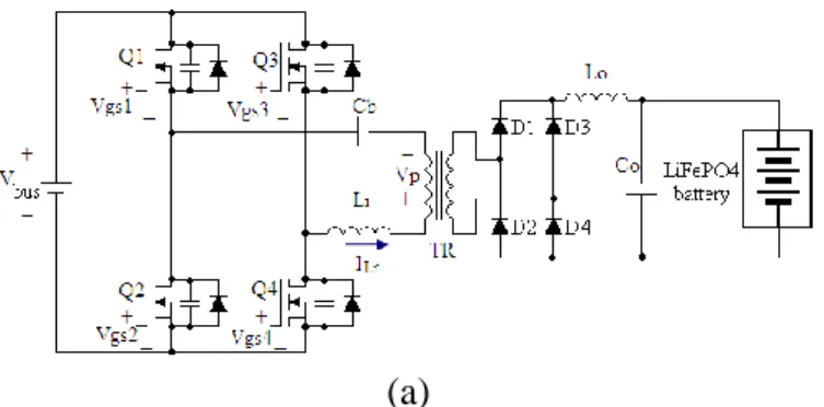
The full-bridge phase-shifted zero-voltage-switching DC-DC converter with secondary full-wave rectification is shown in Fig. 3.
High conversion efficiency and wide-range of well-regulated output voltage features can be achieved due to the phase-shifted soft-switching operation on the primary power switches.
(a)
(b)
Fig. 3 (a) Circuit Schematic and (b) Theoretical Waveforms for the Full-bridge Phase-shifted Converter
C. 3-phase Battery Charging
In this project, a 3-phase charging scheme shown in Fig. 4 is designed for LiFePO4 batteries.
The requirements for long battery lifetime, fast charging speed and simple control can be satisfied.
Charging starts by checking the initial battery voltage. If it is below a threshold voltage (VT), charging with a low current (IB1) will sustain to avoid the occurrence of over-temperature due to high battery impedance. If the battery voltage reaches VT, a fast charging current will be applied until the upper voltage limit (VS) is reached. Then, CV mode starts until either the charging current drops to a threshold value.
Fig. 4 3-phase Charging Scheme for LiFePO4 Batteries
III. Experimental Verifications
A 3kW laboratory prototype for the studied LiFePO4 battery charger has been designed and implemented for electric vehicle applications. The prototype and battery specifications are listed in Table 1 and
Table 2 as follows:
Table 1 Circuit Specifications for the Laboratory Prototype
Parameter Specification AC line
voltage Vac 180V~264V
output voltage Vo nominal 365V; maximum 500V
output current Io 8.3A (rated) power factor PF 0.98 (at nominal
output) efficiency 0.96 (at nominal
output)
dimension L×W×H 400×300×132(mm) (3U height)
Table 2 Battery Specifications Parameter Specification
nominal voltage 320V
maximum charge voltage 365V absolute maximum
voltage 410V
capacity 40Ah
maximum discharge rate 4C
maximum charge rate 4C
continuous charge rate C/2
trickle charge C/5
operating temperature -10 to 60°C
We implemented and tested a 3kW bridgeless PFC converter for LiFePO4 battery charger. The experimental results of a laboratory prototype for the bridgeless PFC converter are shown in Sec.
3.3.1 to verify the feasibility. Finally, a prototype system for the 3kW/ 365V LiFePO4 battery charger was implemented. The experimental results are verified to meet the project goal.
A. 3kW Bridgeless PFC Converter
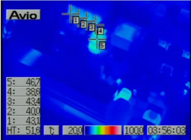
Table 3 shows the experimental results for the bridgeless PFC converter circuit. The conversion efficiency can be around 97% and the input power factor can be up to 0.986. Fig. 5 shows the measured temperature distribution of the PFC board. The highest temperature is less than 60°C.
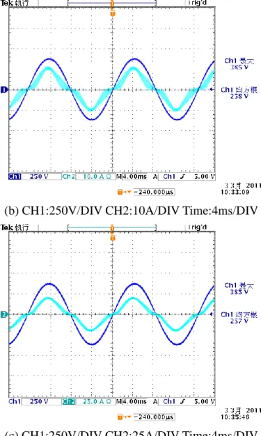
Fig. 6 and Fig. 7 show the measured waveforms of the bridgeless PFC converter under 220V and 264V input conditions.
Table 3 Experimental Results for a 3kW Bridgeless PFC Converter Circuit.
Vin Iin Pin PF Vout Iout Pout η
220 2.83 622.6 0.985 398.2 1.503 598.5 97.27%
220 7.15 1572.8 0.982 397.5 3.784 1504.1 97.16%
220 14.36 3158.8 0.986 396.2 7.576 3001.6 96.48%
264 2.42 612.9 0.955 398.4 1.507 600.5 97.95%
264 5.98 1540.5 0.974 398.1 3.782 1505.6 97.81%
264 12.09 3128.0 0.981 397.4 7.656 3043.0 97.42%
Fig. 5 Measured Temperature Distribution of the 3kW Bridgeless PFC.
(a) CH1:100V/DIV CH2:5A/DIV Time:4ms/DIV
(b) CH1:100V/DIV CH2:10A/DIV Time:4ms/DIV
(c) CH1:100V/DIV CH2:25A/DIV Time:4ms/DIV Fig. 6 Measured Waveforms of the 3kW Bridgeless PFC Converter at 220V Input Condition.
(a)Po=600W,(b)Po=1500W,(c)Po=3000W
(a) CH1:250V/DIV CH2:5A/DIV Time:4ms/DIV
(b) CH1:250V/DIV CH2:10A/DIV Time:4ms/DIV
(c) CH1:250V/DIV CH2:25A/DIV Time:4ms/DIV Fig. 7 Measured Waveforms of the 3kW Bridgeless PFC Converter at 264V Input Condition.
(a)Po=600W,(b)Po=1500W,(c)Po=3000W
B. 3kW/365V Full-bridge Phase-shifted DC-DC Converter
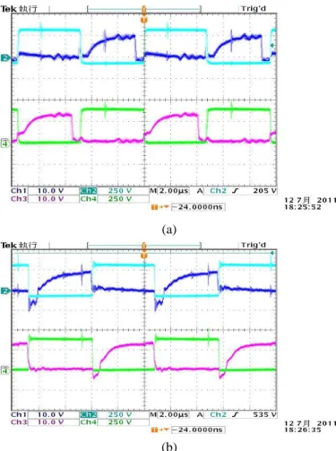
Fig. 8 shows the measured switching waveforms of the 3kW/365V full-bridge phase-shifted converter. The measured conversion efficiency is shown in Table 4. It can be observed that the efficiency of the DC-DC stage can be up to 93.57% at rated load power condition. Thus, the maximum overall efficiency of the two-stage battery charger is about 92%. Fig. 9 show the measured temperature distribution of the DC-DC circuit board. The highest temperature is also less than 60°C.
(a)
(b)
Fig. 8 Measured Switching Waveforms of the 3kW/365V Full-bridge Phase-shifted Converter under (a) 20% Load and (b) 100% Load Conditions Table 4 Experimental Results for the 365V
Full-bridge Phase-shifted DC-DC Converter
Vin Iin Pin Vout Iout Pout η 400.8 1.578 632.3 363.9 1.646 611.1 92.25%
400.5 4.048 1644.0 362.9 4.227 1501.9 94.59%
400.1 8.139 3257.0 358.2 8.491 3001.0 93.57%
Fig. 9 Measured Temperature Distribution of the DC-DC Circuit Board
C. 3kW/ 365V Battery Charger
Fig. 10 shows a photo of the final PCB board
of the studied 3kW battery charger with an input EMI filter and an auxiliary power design. The dimension of this PCB board is less than 370mm×
260mm×90mm.As shown in Table 5, the measured overall efficiency and input power factor is 88.15 % and 0.98 at about 20% load condition while the efficiency and power factor is 88.46 % and 0.99 at rated-load condition.
Fig. 10 A Photo of the final PCB board of the Studied 3kW Battery Charger
Table 5 Measured Performance of the 3kW/ 365V Battery Charger at 230V Input Condition
Parameter 100% load 20% load
PF 0.99 0.98
THDi 11.79 15.58
Vin 227.9 230.1
Iin 13.877 3.041
Vout 349.8 364.1
Iout 7.932 1.6441
Efficiency 88.46 88.15
Fig. 11 shows the measured input voltage and current waveforms of the final prototype system with EMI filter at 20% load/ 230V input condition.
The measured temperature distribution on the PCB board is shown in Fig. 12. The highest temperature is only 49.3°C. Fig. 13 shows the measured input voltage and current waveforms of the final prototype system with EMI filter at rated load/
230V input condition. The measured temperature distribution on the PCB board is shown in Fig. 14.
The highest temperature is 51.6°C. Good thermal
features can be achieved for the 3kW LiFePO4 battery charger due to its high efficiency performance.
Fig. 11 Measured Input Voltage and Current Waveforms at 20% Load/ 230V Input Condition
Fig. 12 Measured Temperature Distribution at 20%
Load/ 230V Input Condition
Fig. 13 Measured Input Voltage and Current Waveforms at Rated Load/ 230V Input Condition
Fig. 14 Measured Temperature Distribution at Rated Load/ 230V Input Condition
The measured input current harmonics are shown in Fig. 15. It can be observed that the current harmonics can meet the requirement of the IEC 61000-3-2 class D standard.
Fig. 15 Measured Input Current Harmonics of the 3kW/ 365V Battery Charger
IV. Conclusion
This project implemented a high efficiency LiFePO4 battery charger with high power factor for electric vehicle applications. A three-phase charging scheme is realized to prolong battery lifetime. A laboratory prototype was built and tested to verify the feasibility of the proposed scheme. The measured efficiency and input power factor can be above 88% and 0.99 at the rated power condition.
Reference
[1] C. C. Hua and M. Y. Lin, “A Study of Charging Control of Lead-acid Battery for Electric Vehicles,” ISIE 2000 Conference, vol.
1, pp: 135-140, Dec. 2000.
[2] R. C. Cope and Y. Podrazhansky, “The Art of Battery Charging,” Proc. 14th Annual Battery Conf. Application Advances, pp. 233-235, Jan.
1999.
[3] S. Harrington and J. Dunlop, “Battery Charge Controller Characteristics in Photovoltaic Systems,” IEEE Aerospace Electronics System Magazine, vol. 7, no. 8, pp. 15-21, 1992.
[4] T. S. Mundra and A. Kumar “An Innovative Battery Charger for Safe Charging of NiMH/NiCd Batteries”, IEEE Transactions on Consumer Electronics, vol. 53, no. 3, pp.
1044-1052, 2007.
[5] F. Boico, B. Lehman and K. Shujaee, “Solar Battery Chargers for NiMH Batteries”, IEEE Transactions on Power Electronics, vol. 22, No.
5, pp. 1600-1609, September 2007.
[6] M. Gonzdez, F.J. Ferrero, J.C. Antbn, and M.A.
Pkez “Considerations to Improve the Practical Design of Universal and Full-Effective NiCd/NiMH Battery Fast Chargers”, Applied Power Electronics Conference (APEC) Proceedings, pp. 167-173, 1999.
[7] J. Díaz, J. A. Martín-Ramos, A. M. Pernía, F.
Nuño, and F. F. Linera “Intelligent and Universal Fast Charger for NiCd and NiMH Batteries in Portable Applications”, IEEE Transaction on Industrial Electronics, vol. 51, no. 4, pp. 857-863, 2004.
[8] Y. S. Wong, W. G. Hurley, and W. H. Wolfle,
“Temperature Compensation Algorithm for Interrupted Charge Control Regime for a VRLA Battery in Standby Applications,” IEEE 23rd Applied Power Electronics Conference and Exposition, 2008, pp. 1278-1283.
[9] E. Koutroulis and K. Kalaitzakis, “Novel Battery Charging Regulation System for Photovoltaic Applications,” IEE Proceedings on Electric Power Applications, Vol. 151, Issue:
2, 2004, pp. 191-197.
[10] M.F.M. Elias, K.M. Nor and A.K. Arof
“Design of Smart Charger for Series for Lithium-Ion Batteries”, IEEE PEDS’05, p.p.
1485-1490, 2005.
[11] J. Wang, Z. Sun, and X. Wei, “Performance and Characteristic Research in LiFePO4 Battery for Electric Vehicle Applications,”
IEEE Vehicle Power and Propulsion Conference, 2009 , pp. 1657-1661.
[12] K. C. Tseng, T. J. Liang, J. F. Chen, and M. T.
Chang, “High Frequency Positive/ Negative Pulse Charger with Power Factor Correction”, IEEE PESC’02, Vol. 2, pp. 671-675.
[13] P. H. Cheng, and C. L. Chen, “A High-Efficiency Fast Charger for Lead-Acid Batteries”, IEEE IECON’02, Vol. 2. pp.
1410-1415.
[14] X. Xu, W. Liu, and A. Q. Huang, “Two-Phase Interleaved Critical Mode PFC Boost Converter with Closed Loop Interleaving Strategy,” IEEE Transactions on Power Electronics, Volume: 24, Issue: 12, 2009, pp.
3003-3013.
[15] J. C. Wang and H. J. Chen, “Design and Analysis of AC/DC Converters with Interleaved Power Factor Correction,” 4th IET Conference on Power Electronics, Machines and Drives, 2008, pp. 485-489.
[16] L. Huber, J. Yungtaek, and, M. M. Jovanovic,
“Performance Evaluation of Bridgeless PFC Boost Rectifiers,” IEEE Transactions on Power Electronics, Volume: 23, Issue: 3, 2008, pp.
1381-1390.