國立臺灣大學工學院土木工程學系 碩士論文
Department of Civil Engineering College of Engineering
National Taiwan University Master Thesis
起停式吊車減盪控制引導系統
A Crane Bang-Bang Control Guiding Method for Sway Reduction
陳鵬元 Peng-Yuan Chen
指導教授:康仕仲 教授 Advisor: Shih-Chung Kang, Ph.D.
中華民國 107 年 6 月
June 2018
誌謝
本篇論文能夠完成,要感謝指導教授康仕仲老師的悉心指導。謝謝康老師的教 誨,讓我不僅是在研究上,亦在想法上獲益良多,也感謝老師提供豐富的資源,讓 我在研究的進程中能夠大膽嘗試,利用各式先進的技術輔助研究。也感謝結構組的
張家銘老師,提供了許多研究上的幫助和支援感謝。感謝CAE 組的師長和同學們,
在這個溫暖的大家庭中完成學業是一件幸福的事。感謝Rlab 的學長和學弟,在我
的研究和實驗上適時地提供各項幫助和諮詢,你們是本研究的完成不可或缺的助 力。感謝身邊在這段時間陪伴我、和我聊天解悶的朋友們。
另外感謝祐彬營造股份有限公司的曾崑彬董事長,大方地提供研究的經費、場 地以及設備供我們使用,公司中的前輩們亦無私地與我們分享了工程實務上的經 驗與心得。是本研究得以順利進行的重要推手。
感謝口試期間,口試委員康仕仲老師、張家銘老師、劉寅春老師以及紀宏霖老 師寶貴的建議與指教,使得本研究更充實和嚴謹。
最後要感謝我的家人,謝謝爸媽將我帶到這個世界,供應我們家三個小孩吃飽 穿暖,放我們探索自己的未來,謝謝你們這段期間的支持與鼓勵。感謝你們,在此 將完成這份論文的喜悅以及成就和你們一起分享。
陳鵬元 謹誌 於台大土木工程研究所 中華民國一〇七年六月
中文摘要
吊車所懸掛之的被吊物具有晃動之問題,其可能影響建築工程之效率。而當發 生大規模晃動時,吊車操作員必須浪費寶貴的時間等待晃動停止。在工程實務上,
較有經驗之操作員可以通過操縱吊臂的旋轉來補償搖擺,但是這種控制方式對於 較無經驗之操作員具有較高的挑戰性。因此,相較於有經驗之操作員,較無經驗之 操作員可能需要花費較多時間來完成同一件吊車運輸任務。另一方面,儘管許多研 究人員持續致力於控制吊車被吊物之晃動,然對於營建業所廣泛使用的旋轉式起 重機則較缺乏相關研究。因此,我們開發了一種吊車減盪方法,本方法可引導較無 經驗的操作員適當地控制動臂來達到減盪的目的,其包括起停式起重機減盪策略 (crane bang-bang sway reduction strategy),基於視覺之吊物感測方法 (vision-based payload sensing method) 和操作員引導方法 (operator guiding method)。首先,視覺 吊物感測方法持續感測被吊物,接下來以起停式減盪策略和操作員引導方法判斷 被吊物之狀態。最後,操作員引導方法引導操作員以適當的操控來減少晃動。在本 研究中我們在旋轉式液壓起重機上進行實地測試以檢驗本方法的被吊物減盪效果。
實驗結果顯示本方法之操控結束時,被吊物之搖晃角度減少了56.5%,同一時間較
有經驗的操作員減少了 14.5%的晃動角度,而自然晃動的情況下則減少了 2.5%。
ABSTRACT
The swaying of the payloads suspended by cranes is a problem that can influence the efficiency of construction projects. When massive sway occurs, the operator is forced to waste precious time to wait until the payload stops. In practice, some operators may compensate the sway by manipulating the rotation of the boom. However, for novice operators, such practice may be challenging to perform. This problem can increase the duration of a crane transporting mission executed by a novice operator. On the other hand, though numerous researchers have been working on sway reduction of cranes, few of them focus on rotary boom cranes, which are widely used in construction industry.
Therefore, we developed a sway reduction method to guide novice operators to properly control the boom to enhance their performance. Our method includes a crane bang-bang sway reduction strategy, a vision-based payload sensing method and an operator guiding method. First, the payload is continuously sensed by the vision-based payload sensing method. Then, the state of the payload is judged basing on the crane bang-bang sway reduction strategy and the operator guiding method. Finally, the operator guiding method guides the operator to reduce sway properly. The method was realized and implemented on an industrial hydraulic rotary boom crane. A field test was conducted to test the sway reduction ability of the system. The result shows that the at the end of the sway reduction of our method, 56.5% of the sway angle was reduced. At the same period, the remaining angle of an experienced operator was 85.5%, and the remaining angle of an uncontrolled sway is 97.5%.
TABLE OF CONTENTS
口試委員會審定書 ... #
誌謝 ... i
中文摘要 ... ii
ABSTRACT ... iii
TABLE OF CONTENTS ... iv
LIST OF FIGURES ... vi
LIST OF TABLES ... viii
Chapter 1 Introduction ... 1
1.1 Swaying Problem of Construction Cranes ... 1
1.2 Sway Reduction Control Strategies ... 3
1.3 Slewing Motion of Hydraulic Rotary Cranes... 5
1.4 Payload Swaying Sensing ... 7
Chapter 2 Research Goal... 9
Chapter 3 Methodology ... 10
3.1 The Crane Bang-Bang Control Guiding Method for Sway Reduction (CBBG Method) ... 10
3.2 Crane Bang-bang Sway Reduction Strategy ... 12
3.3 Vision-Based Payload Sensing Method ... 17
3.4 Operator Guiding Method ... 24
Chapter 4 Implementation ... 30
4.1 System Overview... 30
4.2 System Setup ... 31
Chapter 5 Verification ... 34
5.1 Numerical Test and the Result... 34
5.2 Field test and the Result ... 36
5.3 Result Discussion ... 37
Chapter 6 Conclusion and Future Work ... 43
6.1 Conclusion ... 43
6.2 Future Work ... 44
REFERENCE ... 47
LIST OF FIGURES
Fig. 1-1. A crane boom velocity profile of a bang-bang command. ... 7
Fig. 3-1. The control loop of the CBBG method. ...11
Fig. 3-2. A pendulum system and the applied acceleration (a) and a swaying pendulum system and the applied acceleration (b). ... 13
Fig. 3-3. Acceleration and gravity acceleration applied on the pendulum. ... 15
Fig. 3-4. Illustration of the bang-bang sway reduction strategy. ... 17
Fig. 3-5. Schematic diagram of camera mounting. ... 18
Fig. 3-6. Image acquired by the camera. ... 19
Fig. 3-7. Tracking sequence. ... 20
Fig. 3-8. Tracking marker. ... 21
Fig. 3-9. Original image of the payload (a), image after the threshold (b). ... 21
Fig. 3-10. Binary image of the payload. ... 22
Fig. 3-11. Relation between the camera and the payload (left). Image captured by the camera (Right). ... 22
Fig. 3-12. Relation between the width of the scene and the width of the sensor. ... 23
Fig. 3-13. Schematic diagram of the delay calibration. ... 26
Fig. 3-14. Time-angle function of the swaying payload. ... 27
Fig. 3-15. An example of swaying motion. ... 28
Fig. 3-16. Flow chart of the operator guiding method. ... 29
Fig. 4-1. System architecture of the crane bang-bang control guiding method for sway reduction system. ... 30
Fig. 4-2. The crane and the system setup. ... 31
Fig. 4-3. Smart camera and 3-axis stabilizer setup mounted on the boom tip. ... 32
Fig. 4-4. On and off of the guiding interface and the slewing control lever. ... 33
Fig. 5-1. Pendulum model made for numerical simulation. ... 35
Fig. 5-2. The computed swaying angle as a function of time. ... 35
Fig. 5-3. The uncontrolled sway. ... 37
Fig. 5-4. The controlled sway of a licensed operator performing sway reduction without the sway reduction system. ... 37
Fig. 5-5. The controlled sway of an undertrained operator performing sway reduction with the sway reduction system. ... 37
Fig. 5-6. The comparison between the three field tests. ... 39
Fig. 5-7. The comparison line chart between the three field tests. ... 40
LIST OF TABLES
Table 5-1. The comparison between the three field tests. ... 40 Table 5-2. The comparison between the three field tests at the moment the controlling methods ended. ... 42
Chapter 1 Introduction
1.1 Swaying Problem of Construction Cranes
Rotary cranes have been playing crucial roles in the construction industry since they were introduced. Usually, these machines are heavily used to transport construction materials from point to point in construction sites. The heavy reliance makes the working efficiency of cranes a critical factor that affects the progress rate of construction projects.
Therefore, minimizing the working time of cranes can enhance the efficiency of construction projects [1]. The working cycle of cranes can be roughly divided into three parts, including lifting the load, transporting the load and lowering the load. By accelerating the transporting stage, which is mostly the horizontal rotation of the boom, one can reduce the duration of an operation cycle. However, recklessly speeding up the rotation of a crane boom may result in severe sway motion of the suspended load [2]. This is an undesired phenomenon in construction sites because of its potential to pose danger to the nearby environment. Moreover, if the sway motion exceeds a tolerance level, the operator will have to wait until it stops before any further operation can be executed [3].
Hence, a primary concern of crane control is to move the load as rapid as possible while preventing its sway motion simultaneously [4].
In practice, crane operators can reduce the sway of the payload with special control techniques. During the transporting stage, experienced operators prevent the load from greatly swaying by continuously varying the rotation speed of the boom [2]. In the case that the sway is not successfully prevented at the end of the transporting stage, operators may compensate it by additional slewing motion [3]. One of the compensating methods that are performed after the transporting stage is to rotate the boom in the direction the
payload sways. If done properly, the compensation can significantly eliminate the sway.
In fact, experienced operators can delicately control the boom to slew back and forth in response to the motion of the swaying payload. The acceleration and deceleration of the boom in the controlled slewing motion apply forces to the payload. If the forces are applied at the proper timing and direction, it does negative work to the pendulum system, which reduces the energy of the swaying motion. However, if the force is not well applied, the volume of the negative work can drop, which consequently lead to a poor sway reduction result. The main obstacle for a novice operator to perform a proper compensation after the transporting stage may be the lack of the understanding of the timing to move and stop the boom. Inexperienced operators may have difficulties to delicately control the acceleration and deceleration of the boom at the optimal timing.
This reduces the effectiveness of their sway reduction performance. Hence, a novice operator may take more time to accomplish the same lifting task than an experienced operator. The problems can be even worse in regions with a lower birth rate. With the aging of experienced operators, the need for automated solutions is urging [5].
In this research, we present a method to guide novice operators to perform the sway compensation in the tangential plane of the rotary crane. To simplify the control, we reduce the repeating rotating and stopping of the boom to a single start and stop. In other words, the operator is only required to input a simple bang-bang command that starts and stops the rotation. By guiding the operator to rotate and stop the boom at the proper timing and direction, the method maximizes the negative work done on the pendulum system.
Through this method, the gap between the sway reduction ability of novice operators and experienced operator is expected to be shortened.
1.2 Sway Reduction Control Strategies
Numerous researchers have been dedicating to developing control methods to address these issues [6, 4]. However, while construction industry mostly relies on tower cranes and mobile cranes, research works focus more on other types of cranes. Ramli et al. state that this may be due to the complexity of controlling under-actuated systems such as tower cranes and mobile cranes [4]. On the other hand, they also suggest that developing the control methods basing on real industrial cranes will bring results which are more practical [4].
The strategies of payload swaying control can be divided into two major types: the open-loop control and the closed-loop control. In the following sections, these two control techniques and related research works, which focus on rotary boom crane system, are introduced.
Open-Loop Control Strategy
The open-loop control strategy is a method that pre-sets the transporting motion of the crane to prevent the payload from swaying [2]. This type of control strategy does not acquire feedback to the controller for further adjustment. Hence, it does not require sensors to monitor the motion of the payload [7].
Researches focusing on rotary boom crane system in this category employ techniques including input shaping and filtering. Maleki et al. applied input shaping to a small-scale mobile boom crane [8]. Huang et al. developed an input shaping method combined with feedback control to lower the swaying of payload generated by the operator and cope with the influence of wind [9]. Glossiotis et al. proposed a method that preprocesses the commands input to a rotary crane with a finite impulse response (FIR) filter [10]. Ahmad et al. studied the implementation of infinite impulse response (IIR) filter in hybrid control
strategy and suggested that the proposed control method can suppress the sway of the payload [11].
Closed-Loop Control Strategy
The closed-loop control is a strategy opposite to open-loop control strategy. By receiving data collected by sensors attached to the crane system [2], the closed-loop method can adjust the subsequent control command [4]. This allows the strategy to be more invulnerable to external interference [3].
Researches implementing closed-loop control strategy on rotary boom cranes employ techniques including proportional integral derivative (PID), linear quadratic regulator (LQR), model predictive control (MPC) and neural network (NN). Ahmad et al.
developed and compared a PD and a PD-type fuzzy logic controller. The authors reported that the PD controller performs significantly better than D-type fuzzy logic controller while the latter can respond faster than the former [12]. Furthermore, the authors also developed and compared LQR and PD-type fuzzy logic controller. They reported that the PD-type fuzzy logic controller outperforms the LQR controller significantly [13].
Kawada et al. proposed a variable gain PD controller design scheme as well as a gain- scheduled PD controller design scheme to control the sway of the payload [14, 15]. To cope with the difficulty to find a set of proper control parameters for PD controllers in the time-varying and nonlinear systems, the authors applied genetic algorithms to find the optimal parameters [16, 17]. Ouyang et al. proposed a 2-degree-of-freedom linear controller that to control the sway of the payload and the position of the crane boom [18].
Uchiyama et al. proposed a linear controller based on pole placement approach to control the sway of the payload and the position of the crane boom [19]. Sano et al. developed a linear matrix inequality (LMI) based control method that allows the variation of cable length to suppress payload sway [20]. Arnold et al. realized an MPC approach on a real
harbor mobile crane to perform anti-sway control [21]. Furthermore, the former work was improved by adding additional feedback loop into the system [22]. Nakazono et al.
applied a simple three-layered NN control method to control the sway of the payload [23].
Summary of The Related Sway Reduction Works
Although many control strategies were developed, they mainly reduce the sway of the payload through either automatically controlling crane motion or by modifying the control command input by the operator. However, this may require modification of the crane mechanical system, thereby increasing the difficulty and cost of implementation.
Moreover, the commands input by human operators and computer may disturb each other.
The problem can lead to limited sway reducing result [8]. Hence, we attempt to prevent these issues by guiding the operator rather than directly controlling the crane to reduce the sway.
1.3 Slewing Motion of Hydraulic Rotary Cranes
The slewing of the superstructure is the main approach of a rotary boom crane to transport payloads in the horizontal plane. The motion is typically driven by a hydraulic motor mounted under the superstructure. When the slewing control lever is pushed/pulled to a fixed degree, the boom starts to accelerate in the corresponding direction. After reaching the target velocity, the boom stops accelerating and keep slewing with the constant velocity. Finally, when the control lever is reverted to the original position, the boom starts to decelerate (accelerate in the reversed direction) [24, 25].
In this research, we aim to guide the operator to perform a bang-bang control to reduce sway. Ideally, if such command is input, the boom will perform an isosceles trapezoid velocity variation. The velocity of the constant velocity stage is determined by
the degree the lever is pulled/pushed. However, a crane boom does not necessarily perform a smooth velocity variation during the slewing motion. In fact, vibration can appear at the end of the acceleration and deceleration. This is because the hydraulic system of a crane consists of components such as counterbalance valves and pressure compensated flow valves. These components are reported to cause oscillation and instability in the hydraulic system. On the other hand, the same research also points out that the flexibility of the boom can cause additional instability [26].
Researches were conducted to address the previous problem. Nordhammer et al.
proposed a control method that employs sequential activation of the counterbalance valves and a control method to stabilize the slewing motion [27]. Cristofori et al.
developed an active damping method considering the pressure of flow control valve to reduce the instability in the hydraulic system [28]. Kjelland et al. demonstrate a method that combines input shaping and pressure feedback to cope with the effect of the structural flexibility and hydraulic instability. Their work can considerably smoothen the velocity variation of a crane boom into a trapezoidal-velocity profile [26].
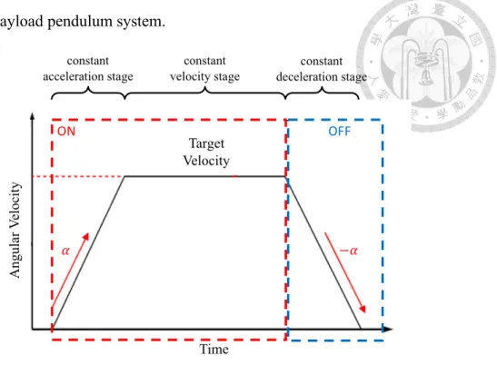
Hence, we regard the velocity variation of the slewing crane boom as an isosceles trapezoid velocity while a fixed-degree bang-bang command is input through the slewing control lever. An example velocity profile is shown in fig. 1-1. The slewing motion of the boom can be divided into three stages: constant acceleration stage, constant velocity stage and constant deceleration stage. When an “on” command is input, the boom starts to accelerate with a constant acceleration. Then, when it reaches the target velocity determined by the degree the lever is pulled/pushed, it ends the acceleration and enters the constant velocity stage. During these two stages, the input command remains “on.”
Then, when an “off” command is input, the boom starts to decelerate until it stops. Among these three stages, the acceleration and deceleration stages are used to disturb the sway
motion of the payload pendulum system.
Fig. 1-1. A crane boom velocity profile of a bang-bang command.
1.4 Payload Swaying Sensing
The method developed in this research aims to indicate operators to input commands at the proper time. This relies on the understanding of the state of the swaying payload at any moment. A vision-based method is utilized to sense the motion of the payload.
Researchers have been working on utilizing image sensors to acquire the state of payloads on different types of cranes. Peng et al. [29] and Sorensen et al. [30] mounted a camera, which points downward, on the trolley of a bridge crane to control the swaying of the payload. However, such installation could be invalid on a rotary boom crane. If a camera is attached to the boom tip directly above the payload, the pitch motion of the boom can vary the direction of the camera. Yoshida and Tsuzuki developed a stereo vision system with two camera point horizontally to the payload to control it on an overhead crane and a rotary boom crane [31, 32]. Their system adjusts the direction of the cameras through servo motors to track the payload. Besides directly observing the payload, Hyla proposed
a method to learn the swaying state of the payload by observing the swaying angle of the cable [33].
Chapter 2 Research Goal
In this research, a vision-based guiding-oriented sway reduction method, which does not require complicated control, is proposed. We aim to guide novice operators to reduce swaying motion of the payload lying on the tangential plane of the rotary crane. The operator is instructed to merely rotate and stop the crane boom at proper timing and direction.
The method observes the motion of the payload with a camera that is equipped perpendicularly on the tip of crane boom. A guiding interface is applied to indicate the operator to perform a simple bang-bang control to the slewing system of the crane boom at the proper timing and direction. Through the slewing motion of the crane boom, the sway of the payload can be reduced. By guiding the operator at the proper timing, the volume of the energy reduced during the practice is expected to be maximized. In other words, we aim to guide novice operators to perform compensation movement to suppress the sway as experienced operators would do if a severe sway occurs at the end of the transporting stage of a lifting task. Furthermore, the work is implemented on a hydraulic rotary crane with a telescopic boom, which can be found on many of the mobile cranes, for the reason of assuring the practicality of this method.
Chapter 3 Methodology
3.1 The Crane Bang-Bang Control Guiding Method for Sway Reduction (CBBG Method)
This work studies on an implementable vision-based guiding-oriented sway reduction method for hydraulic rotary cranes. The method utilizes a guided bang-bang control to control the crane to reduce the tangential sway of the payload based on the observation of the payload with a camera. Hence, we named the method as crane bang- bang control guiding method for sway reduction (CBBG method).
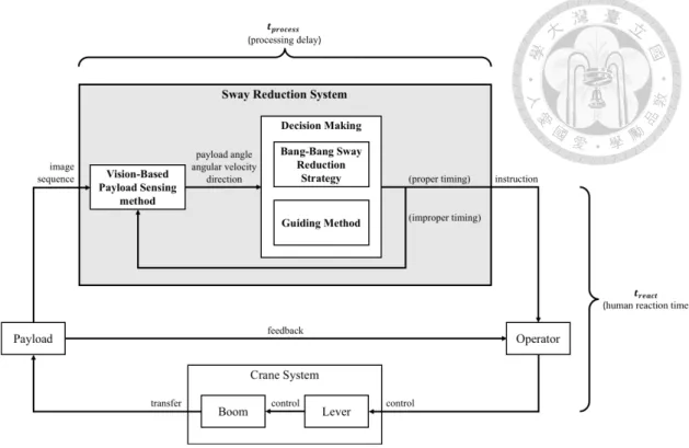
The control loop of the CBBG method is illustrated in Fig. 3-1. The lower part of the diagram represents a conventional crane operation loop. Since human operators are feedback operators, they adjust the control command inputting to the crane through their observation of the payload. Next, they manipulate the lever to control the motion of the boom. As the boom moves, the payload is affected by the boom motion. Then, operators adjust the subsequent command based on their continuous observation [8, 34]. In our research, a sway reduction system is attached to the conventional loop. The additional system is illustrated in the upper part of fig. 3-1. The system takes images of the payload.
Then, it analyses the state of the payload and guides the operator according to the state.
Rather than controlling the crane by itself, the system allows the operator to decide whether to perform the suggested operation. Hence, the method preserves the responding ability of the human to unexpected situations which may not be considered in an automatic system.
Fig. 3-1. The control loop of the CBBG method.
The sway reduction system includes three major parts: the crane bang-bang sway reduction strategy, the vision-based payload sensing method and the guiding method. The crane bang-bang sway reduction strategy and the guiding method compose the decision- making step of the loop. An illustration is shown in Fig. 3-1. The vision-based payload sensing method continuously acquires images of payload and analyses the angle, angular velocity and the swaying direction of the payload on the tangential plane. Then, the information is processed based on the bang-bang sway reduction strategy and the guiding method to determine whether it is the proper timing to perform sway reduction. If the result suggests negative, the system keeps processing succeeding frames. If the result suggests positive, the guiding signal is output to instruct the operator. Since the state of the payload is measured through frames of images, the system works iteratively. In the proposed loop, the processing delay of the sway reduction system and the delay of the reaction time of the operator is considered. The processing delay is denoted as 𝑡"#$%&'', while the delay of the human operator is denoted as 𝑡#&(%). To obtain a better result, the
guiding method calibrates the delay of the system and the reaction time of human operators to determine the proper timing.
In this chapter, we first introduce the crane bang-bang sway reduction strategy. Since we aim to guide the operator to perform a bang-bang control to do negative work to the pendulum system, the strategy was designed to maximize the negative work to eliminate the energy of the pendulum system as much as possible. Then, we present the vision- based payload sensing method. The sensing method is developed to aid the implementation of the sway reduction strategy. Finally, we introduce the guiding method.
The method calibrates the delay in the system and guides the operator to execute the proper operation to reduce sway.
3.2 Crane Bang-bang Sway Reduction Strategy
As shown in fig. 1-1, if a bang-bang command is input through the slewing control lever of a rotary crane, the boom performs a trapezoidal angular velocity variation. At the beginning of the “on” command, the boom undergoes a constant acceleration stage. After the boom reaches the target velocity, the acceleration ends and the boom enters the constant velocity stage. Then, when the “off” command is input, the boom decelerates.
This method aims to utilize the acceleration and deceleration stages to reduce the energy of the pendulum system.
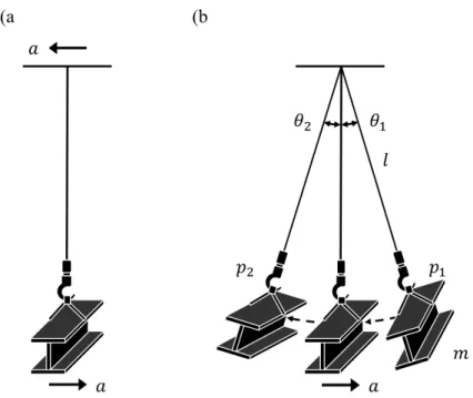
The sway reduction strategy aims to maximize the energy reduced during the acceleration and deceleration stages of the bang-bang control. As shown in fig. 3-2(a), if an acceleration is applied to the upper part of the pendulum system, the pendulum will accelerate in the opposite direction with the same value. This can be observed from the upper part of the pendulum system. According to the work-energy theorem, the work that
the acceleration did to the pendulum equals the variation of the total energy in the pendulum system. As shown in fig. 3-2(b), the acceleration is applied to the pendulum in the opposite direction that the pendulum swings during its travel from point 𝑝+ to 𝑝,. In such condition, the acceleration is doing negative work to the pendulum. In other words, the acceleration is reducing the energy of the sway motion. Therefore, the strategy is designed to maximize the negative work done to the pendulum system in the acceleration and deceleration stages.
Fig. 3-2. A pendulum system and the applied acceleration (a) and a swaying pendulum system and the applied acceleration (b).
We now consider the example situation shown in fig. 3-2(b). A pendulum with mass 𝑚 and length 𝑙 is swaying from point 𝑝+ to 𝑝,. During the entire travel, an acceleration 𝑎 in the opposite direction is applied on the pendulum. The pendulum traveled from 𝜃+ to 𝜃,. The angle denoted here is counterclockwise and starts from the vertical line. Hence, in this case, 𝜃+ is positive, and 𝜃, is negative. This suggests that the tangential component of the acceleration 𝑎 can be denoted as 𝑎 cos 𝜃 no matter 𝜃
is positive or negative. Moreover, when 𝜃 is small, cos 𝜃 ≈ 1. This suggests that 𝑎 cos 𝜃 = 𝑎. Therefore, the negative work 𝑊 done to the pendulum by the acceleration can be calculated as follow:
𝑊 = 9 −𝑚𝑎𝑙 𝑑𝜃<=
<>
= 𝑚𝑎𝑙(𝜃+− 𝜃,). (1)
Since the mass 𝑚, the acceleration 𝑎 and the length 𝑙 remain unchanged, the formula implies that the more angle (𝜃+− 𝜃,) the pendulum travels in the original direction during the time the acceleration applied in the opposite direction, the more negative work is done to the pendulum system. Hence, by maximizing the angle traveled by the pendulum during the acceleration and deceleration stages, the energy reduced can be maximized.
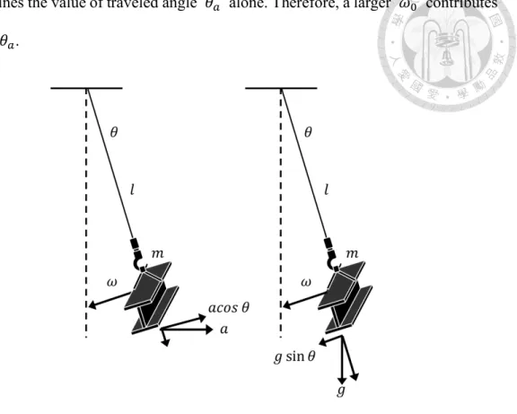
We now consider a pendulum that is swaying from right to left as shown in fig. 3-3.
When the acceleration 𝑎 starts to be applied on the pendulum, it has an initial angular velocity 𝜔C. The left part of the figure illustrates the applied acceleration 𝑎 and its tangential component 𝑎 cos 𝜃 while the right part illustrates the applied gravity acceleration 𝑔 and its tangential component 𝑔 sin 𝜃. If the acceleration 𝑎 is applied to the pendulum for 𝑡( second, the angle traveled during the acceleration 𝜃( = (𝜃+− 𝜃,) by the pendulum can be yielded as:
𝜃( = 9 G𝜔C −𝑎 cos 𝜃 𝑡
𝑙 +𝑔 sin 𝜃 𝑡 𝑙 I 𝑑𝑡
)J C
. (2)
If 𝜃 is small, cos 𝜃 ≈ 1 and sin 𝜃 ≈ 𝜃 ≈ 0. Hence, Eq. 2 can be simplified as:
𝜃( = 9 G𝜔C −𝑎𝑡 𝑙 I 𝑑𝑡
)J C
. (3)
= 𝜔C𝑡(−𝑎𝑡(,
2𝑙 . (4)
According to Eq. (4), since 𝑡(, 𝑎 and 𝑙 remain unchanged, the initial angular velocity
𝜔C determines the value of traveled angle 𝜃( alone. Therefore, a larger 𝜔C contributes to a larger 𝜃(.
Fig. 3-3. Acceleration and gravity acceleration applied on the pendulum.
According to the law of conservation of energy, the maximum angular velocity of the pendulum occurs at the equilibrium point while the pendulum is at the lowest height.
This is because the potential energy of the pendulum is completely transformed into kinetic energy. Therefore, if an acceleration starts to be applied to a swaying pendulum in the opposite direction at the equilibrium point, the angle that the pendulum traveled in the original direction can be maximized. In this case, the initial angular velocity 𝜔C in Eq.
(4) is the velocity of the payload at the equilibrium point. The volume of 𝜔C can be calculated using the law of conservation of energy. Assuming that the potential energy of the pendulum system at the highest point completely transforms into kinetic energy at the equilibrium point, the relationship between the potential energy 𝑈 and the kinetic energy 𝐸 can be written as:
𝑈 = 𝑚𝑔𝑙(1 − cos 𝜃O) = 𝐸 = 1
2𝑚(𝜔C𝑙),. (5)
𝜃O is the angle of the pendulum at the highest point. Then, Eq. (5) can be simplified to:
𝑔(1 − cos 𝜃O) =1
2𝑙(𝜔C),. (6)
From Eq. (6), we can yield:
𝜔C = P2𝑔(1 − cos 𝜃O)
𝑙 . (7)
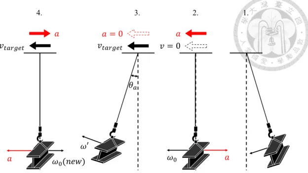
The bang-bang sway reduction strategy is to accelerate the boom when the payload first passes the equilibrium point. Then, it decelerates the boom when the payload sways back and passes the equilibrium point for the second time. The direction that the boom rotates must be the same direction as the payload first passes the equilibrium point. The strategy is illustrated in fig. 3-4. Considering a payload initially sways from right to left, as shown in stage (1) of the figure. When the payload first passes the equilibrium point as shown in stage (2) of the figure, the boom tip starts to accelerate in the swaying direction. At the same moment, the payload has an initial angular velocity 𝜔C in the original swaying direction and an acceleration 𝑎 applied to it in the opposite direction.
After the acceleration duration 𝑡(, the boom tip reaches the target velocity 𝑣)(#R&) as shown in stage (3) of the figure. At this moment, the acceleration of the boom ends.
Consequently, the acceleration applied on the payload ends and a remaining angular velocity 𝜔′ may be observed. Then, when the payload sways back to the equilibrium point in the opposite direction, the boom starts to decelerate from 𝑣)(#R&). Therefore, an acceleration 𝑎 is applied to the payload in the original direction. After 𝑡(, the boom stops and the sway reduction ends.
Fig. 3-4. Illustration of the bang-bang sway reduction strategy.
Through the proposed strategy, we can maximize the energy reduced through the bang-bang control. From Eq. (1), (4) and (7), we can express the energy 𝑊 reduced by the control as follow:
𝑊(𝑚, 𝑎, 𝑙, 𝑡() = 𝑚𝑎𝑙 U𝑡(P2𝑔(1 − cos 𝜃O)
𝑙 −𝑎𝑡(,
2𝑙 V. (8)
In Eq. (8), 𝑚, 𝑎, 𝑙 and 𝑡( are the variables of the crane system.
To achieve the control of the strategy, the sway reduction method guides the operator to input the “on” command in the corresponding direction when the payload first passes the equilibrium point. Then the method guides the operator to input the “off” command when the payload passes the equilibrium point again.
3.3 Vision-Based Payload Sensing Method
To carry out the sway reduction strategy, the understanding of the swaying angle, angular velocity and the swaying direction of the payload is crucial. Therefore, a vision- based payload sensing method is employed. In this section, the camera setup, payload
tracking and image filtering method, swaying angle calculation method, angular velocity and swaying direction calculation method are respectively introduced.
Camera Setup
To acquire images of the payload, a camera is mounted on the tip of the crane boom.
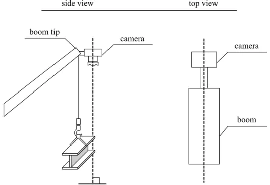
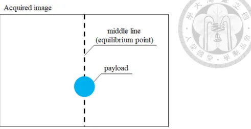
As shown in fig. 3-5, the camera is mounted vertically so that it can acquire images horizontally. Moreover, the camera is aligned to the boom so that the horizontal axis of the images is parallel to the tangent of the crane boom rotation. Based on this setting, the payload will rest on the middle line of the acquired image, as shown in fig. 3-6, when it is in equilibrium point of the tangential swaying motion.
Fig. 3-5. Schematic diagram of camera mounting.
Fig. 3-6. Image acquired by the camera.
Payload Tracking and Image Filtering Method
To understand the swaying angle, angular velocity and the swaying direction of the payload, the sensing method first obtain the position of the payload. Therefore, we designed a tracking method to keep track of the payload. In addition, the method is specially designed to cope with the complex background and illumination variation in the environment of outdoor construction sites.
The tracking sequence is illustrated in fig. 3-7. As shown in the figure, an image is firstly taken by the camera. Next, the image is processed to remove unwanted information.
Then, the object is searched throughout the entire image according to a pre-stored template. Since the image is filtered in advance, the edge of the object is quite distinct.
Hence, an edge matching algorithm using a pre-stored template is employed to find the object in the entire image. Then, the position of the object is updated. If the sway reduction is not ended, the camera acquires a new image and filter it. Then, the object is tracked by mean shift tracking method that search for the object according to a pre-stored template in the nearby region of the last position. If the object is found, the new position will be updated. This process is repeatedly executed to keep track of the object. In the cases that the object is not found by the mean shift method, the tracking process will be
interrupted and the object is searched in the entire image with the same edge matching algorithm. After the object position is retrieved, it is updated for the subsequent tracking loop.
Fig. 3-7. Tracking sequence.
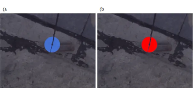
To enhance the possibility of success of the tracking, the image filtering process is necessary. A marker is attached to the payload acting as the target to be tracked. The purpose of the image filtering process is to extract the marker from the image. As shown in fig. 3-8, the marker is a bright blue circular plate placed on the top of the hook with the cable passing through its center. In the image filtering step, an RBG-based color threshold is applied to the image. The threshold only allows pixels with high B-value, low R-value
and G-value to pass. In our case, B-value ranges from 160 to 255. R-value and G-value ranges from 0 to 130. A pixel has to simultaneously satisfy these limitations to pass the threshold. The reason for this setting is that the marker is the only object with high B- value in the image which also contains certain degree of R-value and G-value. On the other hand, restricting high R-value and G-value can eliminate overexposed or nearly white portions in the image. An example image before the threshold and the image after the threshold is shown in fig. 3-9. Then, the resulting image is turned into a binary image as shown in fig. 3-10. Pixels that pass the threshold are turned into white and those do not pass are turn into black. Such image processing is utilized to ensure a successful object tracking.
Fig. 3-8. Tracking marker.
Fig. 3-9. Original image of the payload (a), image after the threshold (b).
Fig. 3-10. Binary image of the payload.
Swaying Angle Calculation Method
After the position of the payload is obtained, the swaying angle can be calculated.
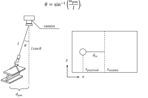
Considering an example condition shown in fig. 3-11, the payload has a swaying angle 𝜃. The real vertical distance between the payload and the middle line is 𝑑"W. The vertical distance between the payload and the middle line on the image sensor is 𝑑X'. The length of the cable suspending the payload is 𝑙. Then, the angle 𝜃 can be calculated as follow:
𝜃 = sinY+G𝑑"W
𝑙 I. (9)
Fig. 3-11. Relation between the camera and the payload (left). Image captured by the camera (right).
Assuming that the length 𝑙 of the cable is known, the real distance 𝑑"W needs to be obtained to calculate 𝜃. When 𝜃 is small, cos 𝜃 ≈ 1. Thus, as shown in the left part of fig. 3-11, we can assume that the vertical distance between the camera and the payload 𝑙 𝑐𝑜𝑠 𝜃 ≈ 𝑙. From fig. 3-12, the ratio between the width of the scene 𝑤' and the width of the image sensor 𝑤X' is the same ration between 𝑙 and the focal length 𝑓 of the lens.
The relation can be denoted as follow:
𝑤' 𝑤X' = 𝑙
𝑓 . (10)
From this relation, the real distance 𝑑"W can be calculated as follow:
𝑑"W = 𝑑X' ∙ 𝑙
𝑓 . (11)
From Eq. (9) and Eq. (11), the swaying angle 𝜃 of the payload is calculated as follow:
𝜃 = sinY+G𝑑X'
𝑓 I. (12)
In our case, the direction of the x-axis of the image is denoted in the right part of fig.
3-11. The distance 𝑑X' is calculated by 𝑥WXaab&− 𝑥"(cb$(a. Hence, 𝑑X' > 0 if the payload is at the right side of the picture and 𝑑X' < 0 if the payload is at the left side.
Consequently, 𝜃 > 0 if the payload sway to the right side and 𝜃 < 0 if the opposite occurs.
Fig. 3-12. Relation between the width of the scene and the width of the sensor.
Angular Velocity and Swaying Direction Calculation Method
After the swaying angle of the payload is obtained, the angular velocity and the swaying direction can be calculated. The angular velocity 𝜔 of the swaying motion is calculated as follow:
𝜔 =𝜃+− 𝜃C
𝛿𝑡 . (13)
In the equation, 𝜃+ is the swaying angle of the payload in current frame while 𝜃C is the swaying angle in last processed frame. 𝛿𝑡 is the time difference between these two frames. It should be noticed that the method does not process the images frame by frame.
In fact, after a frame is processed, the method continues to process the frame captured right after the moment. This is to ensure the obtaining of the real-time payload states.
On the other hand, the direction of the swaying motion is determined by the sign of the angular velocity 𝜔. Since the x-axis of the processed images is pointing from left to right, 𝜔 > 0 if the payload is swaying toward the right and 𝜔 < 0 if the payload is swaying toward left.
3.4 Operator Guiding Method
Basing on the sway reduction strategy and the payload state sensed by the vision- based method, an operator guiding method is developed. According to the strategy, the guiding method guides the operator to control the boom to slew in the corresponding direction when the swaying payload first passes the equilibrium point of the tangential swaying motion. Then, when the payload passes the same point for the second time, the guiding method guides the operator to stop the boom. To reduce the influence of the delay in the system, the method calibrates the issue. In this section, we first introduce the delay calibration of the system. Then, the guiding flow is presented.
Delay Calibration
The delays in the system include the processing delay of the sway reduction system 𝑡"#$%&'' and the delay of the reaction time of human operators 𝑡#&(%). 𝑡"#$%&''
represents the duration of the vision-based payload sensing step and the decision-making step shown in fig.3-1 (b). 𝑡#&(%) represents the reaction time of the human operator. The duration starts from the receiving of the instruction to the completion of the corresponding control command. According to Kosinski, the average reaction time of college-age individuals is about 0.19 seconds [35]. Therefore, we set 𝑡#&(%) as 0.19 seconds in our work.
Fig. 3-13 shows three successive iterations: the processed image #n, #n+1 and #n+2.
The horizontal axis of the diagram represents the proceeding of time while the vertical axis represents the sequence of the processed images. Once an image is taken, a duration 𝑡"#$%&'' is taken to process the image. At the end of the processing, the remaining time 𝑡#&W(Xg of the pendulum to reach the middle line is estimated. It should be noted that, by the time that 𝑡#&W(Xg is estimated, the real remaining time is actually 𝑡#&W(Xg− 𝑡"#$%&''. This is because that 𝑡#&W(Xg is actually the remaining time when the particular image is taken. The right end of the diagram is the moment that the pendulum reaches the equilibrium point. Before it is the end of a colored region. The duration between them is equal to 𝑡#&(%). This implies that the guiding signal should be sent to the operator at the end of the colored region so that the operator can execute the command at the proper moment. The width of the region represents the duration of the acquisition 𝑡h#(W& and the processing 𝑡"#$%&'' of one image frame.
Fig. 3-13. Schematic diagram of the delay calibration.
To obtain a better sway reduction result, the guiding method calibrates the processing delay of the sway reduction system 𝑡"#$%&'' and the delay of the reaction time of human operators 𝑡#&(%). For the situation of the nth image as shown in the first line of fig. 3-13, the processing of the image is completed before the colored region. The actual remaining time (𝑡#&W(Xg− 𝑡"#$%&'') is also estimated. It can be seen that (𝑡#&W(Xg− 𝑡"#$%&'') >
(𝑡h#(W&+ 𝑡"#$%&''+ 𝑡#&(%)). This indicates that it should be enough time remaining to acquire and process another frame for a more accurate estimation of the remaining time.
For the situation of the n+1th image as shown in the second line of fig. 3-13, the processing of the image is completed in the colored region. It can also be seen that (𝑡h#(W&+ 𝑡"#$%&''+ 𝑡#&(%)) ≥ (𝑡#&W(Xg− 𝑡"#$%&'') ≥ 𝑡#&(%). This indicates that there is no enough time to acquire and process another frame and the guiding signal should be sent in this iteration. Thus, the guiding signal is sent to the operator after j𝑡#&W(Xg− 𝑡"#$%&''k − 𝑡#&(%) seconds as shown at the highlighted circle in the figure. For the situation of the n+2th image as shown in the third line of fig. 3-13, the processing of the image is
completed after the colored region. It can also be seen that 𝑡#&(%) > (𝑡#&W(Xg− 𝑡"#$%&'').
This indicates that it is too late to send the guiding signal. Thus, the signal should be sent in the previous iteration. In conclusion, if the processing is completed in the colored region, the guiding signal should be sent in that iteration.
Now we introduce the estimation of the remaining time of the pendulum to reach the middle line 𝑡#&W(Xg. Here we assume that the time-angle function of the swaying motion of the payload approximates to cosine wave. This is the case when we define the swaying motion starts from the maximum angle, as shown in fig. 3-14. Also, we assume that when the swaying angle 𝜃 is small, the period of the swaying motion 𝑇 can be calculated as:
𝑇 = 2𝜋P𝑙
𝑔 . (14)
Fig. 3-14. Time-angle function of the swaying payload.
By calculating the maximum angle and the current angle of the swaying motion, the remaining time 𝑡#&W(Xg can be estimated. As shown in fig. 3-15, a swaying period can be divided into four stages with a quarter period 𝑇/4. We only need to consider the quarters that end with 𝜃 = 0. Namely, the first and the third quarters. Moreover, since the first and the third quarters of a swaying period is vertically symmetrical, we only concern about the absolute value of the swaying angle. We now consider a payload that
is swaying from one side to the equilibrium point as shown in fig. 3-15. The swaying angle 𝜃 of the payload can be calculated with the method proposed earlier. Also, the maximum swaying angle 𝜃W(p is recorded throughout the previous swaying process.
The time 𝑡 can be calculated as follow:
𝑡 =𝑇
4∙cosY+q 𝜃𝜃W(pr
90° . (15)
Then, the remaining time of the pendulum to reach the middle line 𝑡#&W(Xg can be calculated as:
𝑡#&W(Xg =𝑇
4∙ u1 −cosY+q 𝜃𝜃W(pr
90° v. (16)
Fig. 3-15. An example of swaying motion.
Flow of the Operator Guiding Method
The flow of the operator guiding method is designed based on the sway reduction strategy. A flowchart of the sway reduction operation is illustrated in fig. 3-16. The flow starts from the left where the payload sways from one side. Then, the guiding signal indicating “on” in the corresponding direction is output 𝑡#&(%) seconds before the payload passes the equilibrium point. After the operator executes the control command,
the boom starts to accelerate for 𝑡( seconds and reach the constant velocity stage. The payload keeps swaying during the constant velocity stage. Then, it passes the highest point on the other side and starts swaying back. Similarly, the guiding signal indicating
“off” is output 𝑡#&(%) seconds before the payload passes the equilibrium point again.
After the operator executes the control command, the boom starts to decelerate for 𝑡( seconds and finally stops.
Fig. 3-16. Flow chart of the operator guiding method.
Chapter 4 Implementation
In this research, we implemented the vision-based guiding-oriented sway reduction system on an industrial hydraulic rotary crane. The following sections respectively introduce the overview of the proposed system and the setup of the system on a real crane.
4.1 System Overview
The vision-based guiding-oriented sway reduction system includes two main components: the vision-based payload sensing device and the guiding interface. The system architecture is shown in fig. 4-1.
Fig. 4-1. System architecture of the crane bang-bang control guiding method for sway reduction system.
The hardware of the vision-based payload sensing device includes a camera and a computer. The software of the system is an integrated program including the vision-based payload sensing method, the bang-bang sway reduction strategy and the guiding method.
The guiding interface utilizes LEDs to instruct the operator to input proper command at
the proper moment. It is directly controlled by the computer in the vision-based payload sensing device.
4.2 System Setup
In this research, a customized hydraulic rotary crane is employed to examine the developed method. The posture of the crane is fixed. The horizontal outreach of the boom is 5.5 meters. The length of the suspending cable is 5 meters. The crane and the system setup can be seen in fig. 4-2.
Fig. 4-2. The crane and the system setup.
A National Instrument ISC-1781 smart camera [36], which is mounted on the top of the boom tip, is applied as the vision-based payload sensing device. The smart camera is
composed of a camera and a computer. A 6mm c-mount lens is mounted on the camera to capture images. The computer is utilized to execute the controlling program of the entire sway reduction system including the sensing of the payload and the controlling of the guiding interface. In our implementation, it can process averagely 16 frames per second.
To ensure the smart camera is mounted vertically on the tip of the crane boom, a Zhiyun Crane 2 3-axis stabilizer [37] is employed. The detailed setup of the smart camera and the stabilizer mounted on the boom tip is shown in fig. 4-3.
Fig. 4-3. Smart camera and 3-axis stabilizer setup mounted on the boom tip.
A wide-flat-shaped payload which weights 88 kilograms is used to examine the system. The marker that is used to assist the vision-based tracking is placed above the payload.
The guiding interface is composed of two LEDs respectively indicating left and right.
The smart camera controls the LEDs through pulse signal that can turn them on and off.
As shown in the left part of fig. 4-4, when the LED indicating left is turned on, the operator is guided to input the on signal of slewing left. In our case, the operator will push
the slewing control lever. On the other hand, when the LED indicating slewing right is turned on, the operator is guided to pull the slewing control lever as shown in the right part of fig. 4-4. As shown in the middle of fig. 4-4, when LED is turned off, the operator is guided to return the slewing control lever back to the middle position, which inputs the off command.
Fig. 4-4. On and off of the guiding interface and the slewing control lever.
The software of the system is an integrated program developed to control the vision- based payload sensing and the guiding interface based on the Bang-bang sway reduction strategy and the guiding method. The program is compiled in National Instrument Vision Builder for Automated Inspection (VBAI) [38], which provide a tool suite including numerous machine vision tools.
Chapter 5 Verification
To verify our method, we conducted a numerical test and a field test. The purpose of the numerical test is to evaluate the sway reducing ability of the Bang-bang sway reduction strategy. The purpose of the field test is to compare the sway reduction ability of the developed system with the experience of a licensed operator.
5.1 Numerical Test and the Result
The numerical test was conducted to evaluate the sway reducing ability of the Bang- bang sway reduction strategy under the same setup of the field test. Under the setup mentioned in the previous chapter, the angular acceleration of the slewing motion of the boom is approximately 0.245 𝑟𝑎𝑑/𝑠𝑒𝑐,. The target angular velocity of the boom is approximately 0.095 𝑟𝑎𝑑/𝑠𝑒𝑐, when the slewing control lever is fully pushed/pulled.
According to the factors listed upon, the linear acceleration of the boom tip is 1.348 𝑚/𝑠𝑒𝑐,. The target linear velocity of the boom tip is 0.525 𝑚/𝑠𝑒𝑐 when the control lever is fully pushed/pulled. The duration of the acceleration and the deceleration is 𝑡( = 0.389 𝑠𝑒𝑐.
A pendulum model that is shown in fig. 5-1 was used to simulate the suspended payload of the crane. The pendulum equation of motion is:
𝑚𝑎 cos 𝜃 = 𝑚𝑙,𝜃̈ + 𝑚𝑔𝑙 sin 𝜃. (17)
The numerical model is computed in MATLAB R2018a [39] to simulate the behavior of the payload when the bang-bang sway reduction strategy is implemented.
Fig. 5-1. Pendulum model made for numerical simulation.
The result of the numerical simulation is shown in fig. 5-2. In the simulation, the payload was released from one side with 𝜃 = 10° . Then an acceleration 𝑎 = 1.348 𝑚/𝑠𝑒𝑐, was applied to the payload in the opposite direction of its sway for 𝑡( = 0.389 𝑠𝑒𝑐 when it passed the equilibrium point for the third time. At the next time the payload passed the equilibrium, a reversed acceleration with the same value was applied to it with the same duration. As shown in fig. 5-2, the maximum swaying angle of the payload dropped from 10° to 1.61° after the sway reduction, which is an 83.9% drop.
Fig. 5-2. The computed swaying angle as a function of time.
5.2 Field test and the Result
The field tests are conducted to evaluate the performance of the implementation of the vision-based guiding-oriented sway reduction system on the hydraulic rotary crane by examining its sway reducing ability. The tests include an uncontrolled sway, the controlled sway of a licensed operator performing sway reduction without the system and the controlled sway of an undertrained operator performing sway reduction with the sway reduction system. In these tests, artificial sways that lay on the tangential plane of the rotary crane is produced for the tests. The payload is manually pulled to the left side of the boom tip with 𝜃 = 10° and released freely. The setup of the system is reported in the previous chapter. The swaying angle of the payload was recorded by the smart camera.
The result of the uncontrolled sway is shown in fig. 5-3. During the uncontrolled sway test, the payload was freely released and no further disturbance was applied. It can be seen that the sway angle gradually declined over time. The damping ratio of the system is approximately 0.0068. The result of the controlled sway of a licensed operator performing sway reduction without the sway reduction system is shown in fig. 5-4.
During the test of the licensed operator without the system, the operator started controlling right after the payload is released. Then, the operator ceased controlling the boom after 27.3 seconds. The duration of the control is 27.3 seconds. The result of the controlled sway of an undertrained operator performing sway reduction with the sway reduction system is shown in fig. 5-5. During the test of the undertrained operator with the system, the operator started to input the “on” command at 1.14 second. Then, the operator input the “off” command at 3.03 second. The duration of the control is 1.89 seconds. After the sway reduction control was finished, the second mode of the pendulum vibration can be observed from the relatively dense wave shown in the front of fig. 5-5.
Fig. 5-3. The uncontrolled sway.
Fig. 5-4. The controlled sway of a licensed operator performing sway reduction without the sway reduction system.
Fig. 5-5. The controlled sway of an undertrained operator performing sway reduction with the sway reduction system.
5.3 Result Discussion
In fig. 5-6, the uncontrolled sway, the controlled sway of a licensed operator
performing sway reduction without the system and the controlled sway of an undertrained operator performing sway reduction with the proposed system are compared. In these charts, the maximum values were converted into 100%. Thus, the waves settle in the range from 1 to -1. Moreover, peak envelopes are also presented in the charts. The envelopes were calculated through the built-in envelope function in MATLAB. We utilize these envelopes to represent the decline of the sway angle of these tests. As shown in the figure, the angle of the sway controlled by the licensed operator is significantly smaller after the sway reduction is completed. Then, the angle of the sway controlled by the undertrained operator with the sway reduction system is even smaller than the one controlled by the licensed operator. This may partly because of the relatively shorter sway period appeared in the front of the record since the higher vibration frequency dampens energy more quickly.
Fig. 5-6. The comparison between the three field tests.
In table 5-1, to further compare the results of the three tests, we compare the distance between the upper envelope and the lower envelope at the moment the 5th, 10th, 15th, 20th, 25th, 30th, 35th, 40th, 45th and 50th cycle of the uncontrolled sway occurred. Since the wave was converted into the range from -1 to 1, we can assume that the distance between the upper and the lower envelope to be 2 at the full state of the pendulum system.
In fig. 5-7, the comparison is illustrated as a line chart, and the value is converted into the percentage.
Table 5-1. The comparison between the three field tests.
Uncontrolled sway Licensed operator without CBBG
method
Undertrained operator with CBBG
method remaining
distance % remaining
distance % remaining
distance %
𝑡 = 0 sec 2.00 100% 2.00 100% 2.00 100%
5th cycle
(𝑡 = 23.89s ) 1.77 88.4% 0.53 26.7% 0.29 14.3%
10th cycle
(𝑡 = 48.00s) 1.54 77.0% 0.43 21.3% 0.16 8.2%
15th cycle
(𝑡 = 72.20s) 1.30 64.8% 0.41 20.4% 0.12 5.8%
20th cycle
(𝑡 = 96.34s) 1.02 50.9% 0.38 19.1% 0.10 4.9%
25th cycle
(𝑡 = 120.57𝑠) 0.68 34.9% 0.36 18.0% 0.08 4.0%
30th cycle
(𝑡 = 144.51s) 0.50 25.2% 0.34 16.8% 0.07 3.5%
35th cycle
(𝑡 = 168.49s) 0.41 20.3% 0.31 15.5% 0.07 3.3%
40th cycle
(𝑡 = 192.31s) 0.37 28.6% 0.29 14.3% 0.06 2.8%
45th cycle
(𝑡 = 215.94s) 0.33 16.4% 0.26 13.1% 0.05 2.7%
50th cycle
(𝑡 = 239.60𝑠) 0.28 14.0% 0.24 11.9% 0.05 2.6%
Fig. 5-7. The comparison line chart between the three field tests.
In fig. 5-7, we can see that both the controlled sways of the licensed operator without CBBG method and the sway of the undertrained operator with CBBG method
immediately reduced a considerable percent of the sway. Moreover, it is pretty clear that with the help from CBBG method, a novice operator reduced more sway than the experienced operator without the method. In fact, after 23.9 seconds, the remaining sway of the undertrained operator is only 54.7% of the remaining sway of the licensed operator.
Then, the rate is lower to 38.5% at 𝑡 = 48.0 sec. After 𝑡 = 144.5 sec, the rate is even lower to almost 20% and remains similar in the rest of the record.
Additionally, we are also interested in the comparison between the CBBG method and the conventional method at the moments the CBBG and conventional method stopped.
As shown in table 5-2, the remaining sway angle of the CBBG method at the moment the controlling was ceased at 𝑡 = 3.03 sec is 43.5% of the full state. At the same moment, the remaining angle of the conventional method is 85.5%. In other words, the CBBG method reduced 56.5% of the angle while the conventional only reduced 14.5% at the same moment when the CBBG method finished controlling the boom. The angle reduced by CBBG method is 3.9 times larger than the conventional method when CBBG method was finished. At the moment the experienced operator ceased controlling, which is 𝑡 = 27.30 sec, the remaining angle of the conventional method is 25%. At the same moment, the remaining angle of the CBBG method is 13%. In other words, the conventional reduced 75% of the sway angle when it was finished. However, at the same moment, the remaining angle of the CBBG method is only 52% of the former.
Table 5-2. The comparison between the three field tests at the moment the controlling methods ended.
Uncontrolled sway Licensed operator without CBBG
method
Undertrained operator with CBBG
method remaining
distance % remaining
distance % remaining
distance %
𝑡 = 3.03 s 1.95 97.5% 1.71 85.5% 0.87 43.5%
𝑡 = 27.30s 1.74 87.0% 0.50 25.0% 0.26 13.0%
In sum, in this case, the sway reduction performed by a novice operator with CBBG method outperformed the sway reduction performed by an experienced operator without the method in two aspects. The first one is that the controlling duration of the CBBG method is shorter than the conventional method. In fact, the CBBG method only took 1.89 seconds while the conventional method took 27.3 seconds. The second one is that the sway reduction ability of the CBBG method performed by a novice operator is better than the conventional method performed by an experienced operator. Therefore, in this case, we can state that the CBBG method does aid a novice operator to perform a better sway reduction in a shorter duration compared to the conventional method performed by an experienced operator.
Chapter 6 Conclusion and Future Work
6.1 Conclusion
In this research, we developed a crane bang-bang control guiding method for sway reduction of hydraulic rotary cranes. The method includes three parts: the bang-bang sway reduction strategy, the vision-based payload sensing method and the operator guiding method. The system was implemented on an industrial hydraulic rotary crane for validation. The method guides the operator to input a simple bang-bang command to the slewing control lever of the crane to reduce the payload sway lying on the tangential plane.
According to the field tests, in the case we studied, the CBBG method can aid a novice operator to perform a sway reduction that is better than the one performed by an experienced operator in a shorter duration.
The bang-bang sway reduction strategy is a guidable strategy to reduce payload sway in the tangential plane. It only requires the boom to accelerate and decelerate at proper timing and direction. According to the numerical test, in the case we studied, 84% of the swaying angle was reduced after the sway reduction was executed.
The vision-based payload sensing is a sensing method that is designed to track the position of the payload. Then, it calculates the swaying angle, angular velocity and the swaying direction according to the position and the setup of the crane. The sensing method was designed to aid the implementation of the sway reduction strategy.
The operator guiding method is to instruct the operator to perform the sway reduction control according to the sway reduction strategy. It is designed to calibrate the delay of the processing and the reaction time of human by estimating the remaining time of the payload to reach the equilibrium point.