Unusual refractions in photonic crystals based on polymer-dispersed liquid crystal films
Shing-Trong Wu
Department of Physics, National Cheng Kung University, Tainan, Taiwan 701, Republic of China Ming Shian Li
Institute of Electro-optical Science and Engineering, National Cheng Kung University, Tainan, Taiwan 701, Republic of China
Andy Ying-Guey Fuha兲
Department of Physics, and Institute of Electro-optical Science and Engineering, National Cheng Kung University, Tainan, Taiwan 701, Republic of China
共Received 24 August 2007; accepted 5 November 2007; published online 20 December 2007兲 This work describes unusual refractive phenomena from a hexagonally close-packed共hcp兲 photonic crystal共PC兲 based on a holographic polymer dispersed liquid crystal film. The refracted collimated beams comprise positive and negative refractions and can be switched to exhibit the negative refraction part only by changing the incident angle or the wavelength of the incident beam. The equal frequency surfaces are adopted to analyze the refractions of light both inside and outside the hcp PC. © 2007 American Institute of Physics. 关DOI:10.1063/1.2817962兴
The complex refraction of light in photonic crystals 共PCs兲 has been extensively studied in recent years, uncover- ing unnatural effects such as negative refraction,1,2 super- prism effect,3,4 and self-collimation.5 Some recently pro- posed applications that exploit these phenomena include supersensible light deflection spot-size conversion and opti- cal flow guiding.6,7Recently, self-collimation in simple two- dimensional共2D兲 PCs was studied using flat equifrequency surface共EFS兲.8The incident light is split into two collimated beams that do not require a linear defect to act as a wave- guide, and the beam waist remains unchanged through the light propagation.
Most 2D PCs are fabricated using semiconductor sub- strates or fibers with air holes共the so-called photonic crystal fiber兲 or dielectric rods that are formed by electrochemical etching or chemical vapor deposition.9 Light transmission through a photonic crystal fiber infiltrated with liquid crys- tals 共LCs兲 can be tuned electrically or thermally.10,11 This work studies the refraction phenomena when a Gaussian beam is incident onto a 2D hexagonally close-packed共hcp兲 PC. When beams are incident at various angles onto a PC, several phenomena, including negative refraction and anomalous reflection are observed.
A 2D hcp PC is based on a nanosized HPDLC. Details of the sample fabrication have been presented elsewhere.4 The HPDLC film contains ordered 2D nanosized LC domains that are embedded in a polymer matrix, as presented in the inset of Fig.1. The lattice constant estimated from the scan- ning electron microscopy image is⬃350 nm and the width of the square dark voids is ⬃150 nm. The sample is
⬃25m thick. The polymer matrix has a refractive index of
⬃1.56 共NOA81, Norland兲, and the lattice points comprise LC共E7, Merck兲 with ordinary and extraordinary indices of no= 1.5216 and ne= 1.7462, respectively.
An argon/krypton mixed gas laser共Coherent兲 with mul- tiline output is incident onto the 2D hcp PC at various angles to analyze the refraction behaviors from the HPDLC PC. The beam waist of the laser is⬃1.5 mm. Figure 1 presents the
experimental setup that is used to observe the refraction beams. A TE-polarized laser beam is incident onto the sample from air, propagates into the 2D hcp PC, and then is projected on a screen. The sample is mounted on a rotating stage and its surface normal line makes an angle共inc兲 with the incident laser beam. The incident beams are chosen to be between the⌫M-direction and the ⌫K-direction. In this ex- periment, a charged-coupled device camera is located in front of the sample. The inset in Fig. 1 labels the angles between the refraction and the normal to the surface. The incident light may be refracted positively or negatively, and a refracted beam is dispersed over a spread angle. Therefore, the refraction angles of an incident beam are denotedp1to
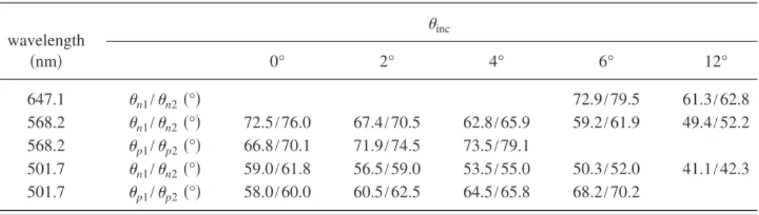
p2and n1 ton2 for positive and negative refractions, re- spectively. Accordingly, the angle of separation is given by 共sep=p1+n1兲, which is the sum of inner angles between the two refraction beams. The spread angles of the refracted beam are p=p2−p1 and n=n2−n1 for positive and negative refractions. Table I summarizes the measured re- fraction angles of three different-color beams 共=647.1, 568.2, and 501.7 nm兲 incident at various anglesinc.
Figure2 displays the refraction images recorded from a HPDLC PC at decreasing wavelengths关共a兲 =647.1 nm, 共b兲 568.2 nm, and共c兲 501.7 nm兴 at various angles of incidence.
Experimentally, the HPDLC PC is rotated clockwise 共or
a兲Electronic mail: [email protected].
FIG. 1.共Color online兲 Schematic experimental setup, geometric structure of hcp PC and characteristics of refraction beams. The lattice vectors a1and a2 and reciprocal lattice vectors b1and b2are presented on the right.
APPLIED PHYSICS LETTERS 91, 251117共2007兲
0003-6951/2007/91共25兲/251117/3/$23.00 91, 251117-1 © 2007 American Institute of Physics
Downloaded 07 Apr 2010 to 140.116.208.53. Redistribution subject to AIP license or copyright; see http://apl.aip.org/apl/copyright.jsp
counterclockwise兲 from normal incidence, to yield a positive 共or negative兲 incident angle. The red light 共=647.1 nm兲 does not refract at normal incidence共inc⬃0°兲, and does not exhibit negative refraction until the incident angle is⬃6°, as presented in Fig. 2共a兲. The refracted beam at an incident angle of 6° diverges and exhibits asymmetrical distribution as compared with the Gaussian shape of the incident beam; it has two bright regions on the screen. Increasing the incident angle causes the negative refraction beam to move toward the center. However, the intensity of the refracted beam be- comes weaker beyond the critical angleinc⬃12°.
The yellow refraction comprises both positive and nega- tive refracted beams at incident angles of less than 5°关Fig.
2共b兲兴. The separation angles 共sep兲 or the angles between the positive and negative collimated beams are around the same atsep⬃139°. Notably, the overall refractions from counter- clockwise rotated and clockwise rotated samples are oppo- site, as shown in Fig. 2共b兲. The positive refraction beam diverges and moves outward while the negative refraction beam moves inward to the center as the incident angle in- creases. The profiles of positive refracted beams change from that of a collimated beam 关Fig.2共b兲, 0°兴, through that of a dispersed beam关Fig.2共b兲, 2°兴, and then to that of two par- allel beams关Fig.2共b兲, 4°兴. The figures present the changes in the profiles of the refracted beams. The positive refraction of the yellow beam is finally eliminated atinc⬎5°, indicating that it refracts only negatively at an angle of incidence of
⬃6°. The negative refracted beam becomes more convergent as it moves inward to the center, and the intensity becomes weaker beyond the critical angleinc⬃10°.
The refraction of the green light as the sample is rotated is quite similar to that of yellow light关Fig.2共c兲兴. It refracts negatively only atinc⬎10°. The negative refraction angles of green light are smaller than that of the yellow light. The dispersions of the beam profiles are not as pronounced as that of the yellow light. Notably, both negative and positive refraction beams remain for lights of smaller wavelengths 共=488 and 476.5 nm兲 and they exhibit the same behavior during rotation. If we define diffraction efficiency
= Ip共n兲/IT, where Ip共n兲and ITare the intensity of the positive 共negative兲 reflection light and transmitted light, respectively.
The maximum diffraction efficiency by this photonic crystal is achieved with the yellow light atinc⬃2° 关Fig.2共b兲兴, and
p共n兲is⬃2%.
Variations in the refraction angles of the yellow and green wavelengths withinc⬃0°, based on the measurements in Fig.2are measured共since the red light does not refract at normal incidence, it is not included in this part of the experi- ment兲. The yellow light diverges more than the green as it passes through the 2D hcp PC. The spread angles of negative and positive refractions are estimated to ben1⬃72.5°, n2
⬃76.0° and p1⬃66.8°, p2⬃70.1° for yellow light, and
n1⬃59.0°,n2⬃61.8° andp1⬃58.0°p2⬃60.0° for green light, respectively. Accordingly, the refractions of green and yellow lights spread over angles of p,501.7⬃2.0° and
p,568.2⬃3.3°, respectively. The field distributions of the positive and negative refracted beams are not completely symmetrical at normal incidence. The cause is believed to result from a slight tilt of the PC structure with the glass substrate in our sample, since rotating the sample slightly 共⬍1°兲 makes the refractions symmetrical.
The incident beam that impinges on a PC decomposes into a Fourier series of plane waves,12,13
Hk=
兺
n,m
hn,m共k兲H0exp共ikn,m· r兲, kn,m= k + Gn,m, 共1兲 where k is the wave vector of the incident wave, hn,m共k兲 are the Fourier coefficients, Gn,m= nb1+ mb2 are the reciprocal vectors, and n and m are integers. According to momentum conservation condition, defined by the continuity of the tan- gential共x axis兲 component of the incident wave vector across the interface, k储 satisfies
k储n,m= kn,m· ex= k · ex+ m⫻2
a , 共2兲
where a is the lattice constant共⬃350 nm兲. The electromag- netic Bloch waves comprise these共n,m兲 plane waves with the Fourier coefficients hn,m共k兲, which determine the disper- sion relation of light. Accordingly, EFS calculated by the
TABLE I. Refraction angles from HPDLC PC for various incident angles and light wavelengths.
wavelength 共nm兲
inc
0° 2° 4° 6° 12°
647.1 n1/n2共°兲 72.9/79.5 61.3/62.8
568.2 n1/n2共°兲 72.5/76.0 67.4/70.5 62.8/65.9 59.2/61.9 49.4/52.2 568.2 p1/p2共°兲 66.8/70.1 71.9/74.5 73.5/79.1
501.7 n1/n2共°兲 59.0/61.8 56.5/59.0 53.5/55.0 50.3/52.0 41.1/42.3 501.7 p1/p2共°兲 58.0/60.0 60.5/62.5 64.5/65.8 68.2/70.2
FIG. 2. 共Color online兲 Recorded refraction images from a HPDLC PC at decreasing wavelengths关共a兲 =647.1 nm, 共b兲 568.2 nm, and 共c兲 501.7 nm兴 and various angles of incidence indicated on the left sides. Experimentally, the HPDLC PC共Fig.1兲 is rotated clockwise 共or counterclockwise兲 from normal incidence, defining a positive共or negative兲 angle of incidence. The wedged or rodlike symbols in Figs.2共b兲and2共c兲are used to schematically depict the field profiles of the refracted beams共above 0°, 2°, 4°, and 6°兲.
251117-2 Wu, Li, and Fuh Appl. Phys. Lett. 91, 251117共2007兲
Downloaded 07 Apr 2010 to 140.116.208.53. Redistribution subject to AIP license or copyright; see http://apl.aip.org/apl/copyright.jsp
plane wave expansion method can be used conveniently to predict wave refraction in PCs.
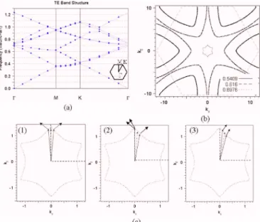
Figure3共a兲presents the TE band diagram of the HPDLC PC with a background index共np兲 of 1.56 and an index mis- match共⌬n兲 of 0.2. The weak modulation of HPDLC PC does not possess an apparent band gap. The dispersion relation that results from diffraction at the band edge alters the field of the transmission band. Figure3共b兲depicts the EFS of the second band at a/⬃0.5409, 0.616, and 0.6976 共or
= 647.1, 568.2, and 501.7 nm兲. Negative refraction effects are easily realized near the top of the first or the second band where the photonic “effective mass” is negative. The shapes of EFS for the hcp PC are hexagonal stars in the second band at wavelength共⬃501.7 nm兲 关Fig. 3共c兲兴. Here, the EFS is closed and helps one to explain the dispersion of refracted beams in PC. Near the top of the second band, the dispersion contours become convex around the corner. The highly curved, strongly anisotropic parts of the dispersion surfaces result in nontrivial effects on refraction.
In PCs, the group velocity vg=k determines the di- rection of light propagation. The group velocity vg is then given by the gradient vector of the EFS. The dispersions of light occur in three steps, as the incident lights face different regions of the convex 共of the EFS兲 that were presented in Fig. 3共c兲. The light cone of a normally incident beam is related to both sides of the EFS corner in consideration of the refraction 关Fig. 3共c兲 共1兲兴. The beam waist of the refracted beam is maintained in propagation, since the incident beam faces the approximately linear area of the EFS. The refrac- tion is two collimated beams, one refracted positively and the other refracted negatively. The wave vectors of positive 共kp兲 and negative 共kn兲 refraction beams and reciprocal vec- tors共kp− kn兲 are expressed as
kp= kin+ n1b1+ m1b2, kn= kin+ n2b1+ m2b2,
kp− kn= Gm,n. 共3兲
In this case, the magnitudes of the reciprocal lattice vectors 共b1, b2, see Fig.1.兲 are 兩b1兩=兩b2兩=共2/a兲⫻共2/冑3兲. Compar- ing the refraction-beam direction at=501.7 nm at quasinor- mal incidence with the reciprocal lattice vectors suggests that the Fourier components of the refraction at n1= −1, m1= 1 and n2= 1, m2= 0 are the positive refraction wave vector共kp兲 and the negative refraction wave vector 共kn兲, respectively.
Based on straightforward calculation, the positive and nega- tive diffraction angles are estimated to be ⬃+61° at
= 501.7 nm.共The x-axis component of kinis neglected in the calculation for a quasinormal incident.兲 The theoretical pre- diction is close to the experimental refraction angles which are n1⬃59.0°, n2⬃61.8° and p1⬃58.0° p2⬃60.0° for negative and positive refractions, respectively 共Table I兲. As the incident angle increases to⬃6° 关Fig.3共c兲共2兲兴, the posi- tive refracted beam hits the star tip and becomes divergent, while the negative beam remains collimated. The divergent behavior is similar to that of the concave lens in Ref. 5.
Finally, when the incident angle is further increased 关Fig.
3共c兲共3兲兴, the negative refracted beam dominates the propa- gation as the beam hits only one side of the corner. A nega- tive refraction with a collimated beam is obtained. The above arguments explain the refractions of yellow and red beams.
In conclusion, this work demonstrated unnatural refrac- tions that occur when a Gaussian beam is incident on a 2D HPDLC PC. The strongly anisotropic parts of the dispersion surfaces give nontrivial effects on refraction. Incident light can be refracted to split into positive- and negative-refraction beams or only negative refraction using dispersion contours that are convex around the corner at the top of the second band. The refractions can be switched from two collimated beams to negative refraction by varying the angle of inci- dence or the wavelength of light. Additionally, the beam shape can be controlled to be collimated or divergent.
The authors would like to thank the National Science Council of the Republic of China共Taiwan兲 and the National Cheng Kung University 共NCKU兲 for financially supporting this research under Contract Nos. NSC 95-2112-M-006-022- MY3 and NCKU Landmark project B0055, respectively.
1E. Schonbrun, Q. Wu, W. Park, T. Yamashita, C. J. Summers, M. Abashin, and Y. Fainman, Appl. Phys. Lett. 90, 041113共2007兲.
2S. Foteinopoulou and C. M. Soukoulis, Phys. Rev. B 67, 235107共2003兲.
3H. Kosaka, T. Kawashima, A. Tomita, M. Notomi, T. Tamamura, T. Sato, and S. Kawakami, Phys. Rev. B 58, R10096共1998兲.
4M. S. Li, S. T. Wu, and A. Y.-G. Fuh, Appl. Phys. Lett. 88, 091109 共2006兲.
5H. Kosaka, T. Kawashima, A. Tomita, M. Notomi, T. Tamamura, T. Sato, and S. Kawakamib, Appl. Phys. Lett. 74, 1212共1999兲.
6H. Kosaka, T. Kawashima, A. Tomita, M. Notomi, T. Tamamura, T. Sato, and S. Kawakami, Appl. Phys. Lett. 74, 1370共1999兲.
7L. Wu, M. Mazilu, J.-F. Gallet, and T. F. Krauss, Appl. Phys. Lett. 86, 211106共2005兲.
8A. Kim, K. B. Chung, and J. W. Wu, Appl. Phys. Lett. 89, 251120共2006兲.
9A. Birner, R. B. Wehrspohn, U. M. Gösele, and K. Busch, Adv. Mater.
共Weinheim, Ger.兲 13, 377 共2001兲.
10F. Du, Y. Q. Lu, and S. T. Wu, Appl. Phys. Lett. 85, 2181共2004兲.
11T. T. Alkeskjold, J. Lægsgaard, A. Bjarklev, D. S. Hermann, A. Anawati, J. Broeng, J. Li, and S. T. Wu, Opt. Express 12, 5857共2004兲.
12B. Lombardet, L. A. Dunbar, R. Ferrini, and R. Houdré, J. Opt. Soc. Am.
B 22, 1179共2005兲.
13I. D. Leon and F. S. Roux, Phys. Rev. B 71, 235105共2005兲.
FIG. 3.共Color online兲 共a兲 Band structure and 共b兲 equifrequency surface for the second band of TE-polarized light with a/=0.6976, 0.616, and 0.5409 共or =501.7, 568.2, and 647.1 nm兲, which propagates in 2D hexagonal lat- tice HPDLC PCs.共c兲 Direction of propagation at normalized frequency, a/=0.6976, in the PC for angles of incidence, 共1兲 0°, 共2兲 6° and 共3兲 12°.
251117-3 Wu, Li, and Fuh Appl. Phys. Lett. 91, 251117共2007兲
Downloaded 07 Apr 2010 to 140.116.208.53. Redistribution subject to AIP license or copyright; see http://apl.aip.org/apl/copyright.jsp