SPECIAL FEATURE REAL- TIME EMBEDDED SYSTE Placing forced Q S
checkpoints in distributed real-time embedded
systems
by Jane-Ferng Chiu and Ge-Ming Chiu
An efficient scheme for placing forced checkpoints in a distributed real-time embedded system so as to eliminate useless checkpoints is presented. The notion of primary non-causal intervals is introduced; these intervals are shown
to be the only candidates that need to be considered for inserting a minimum number of forced checkpoints. An efficient algorithm is then used to identify the
primary non-causal intervals where forced checkpoints should be inserted. The algorithm first converts the original problem to another problem on a directed graph, which may reflect the existence of useless checkpoints. The new problem
can be efficiently solved using existing methods.
ontrol applications such as industrial process control, aircraft, robotics and automotive control have to maintain a very high level of
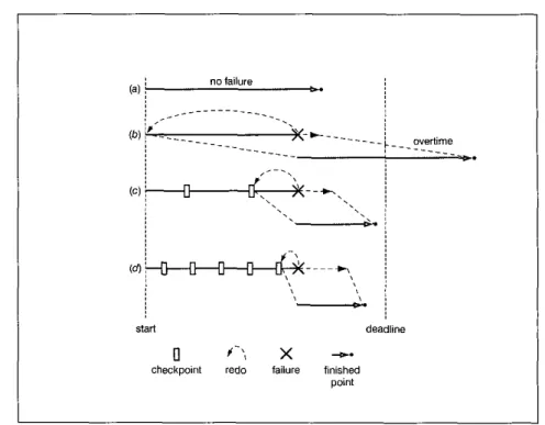
C safe@, typically defined as the avoidance of unplanned events resulting in death, injury and damage, or loss of property. Fig. 1 illustrates the computing time of a real-time embedded system with horizontal lines.
Fig. l(uj shows that a process finished the computing before the deadline without failure, but Fig. l(bj shows that the completed time will exceed the deadline when a process has to he repeated from the beginning because of failure. Thus, fault-tolerant techniques are often embedded to provide predictable performance in the presence of malfunction of safety~critical systems.' Work on fault masking achieves this goal by using spatial redundancy, which is expensive. A less expen- sive approach is that of using time redundancy, which typically does not require a large amount of extra resources and is amenable to embedded systems!
A checkjoint at a process is the saved state of the process, which includes v a l u s of the data variables and contents of the system register^.^ In Fig. 1, the short orange bars indicate checkpoints. If a failure occurs in the system, the failed processes may recover from their checkpoints without restarting from the beginning, as
shown in Fig. l(c) and (d). The more checkpoints there are in a process, the less time is required for repeating a process. However, checkpoint schemes depend on time redundancy, and they could also affect the correctness of the system by causing deadlines to be missed. One way to guarantee that all timing and resource constraints will be met is to statically schedule all communication and checkpoints to meet their deadlines.
In many cases and citations we need to statically schedule communication and checkpoints, such as reliability prediction of distributed embedded fault- tolerant systems, embedded diagnostic systems etc.
Therefore, it is imperative to know the occurrences of all checkpoints and the communication patterns of all nodes prior to a distributed computation beginning in such systems. In particular, a set of checkpoints may be specified for each process that reflects the process's individual needs. These checkpoints are called basic checkpoints? Basic checkpoints are normally deter- mined independently and are inserted in the processes prior to their execution.
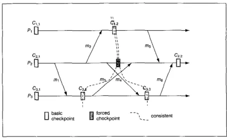
However, in distributed real~time embedded systems, dependency between the states of different processes may be caused by message communication. In Fig. 2, there are three processes, A, F'z, and P3, with six
A
COMPUTING & CONTROL ENGINEERING JOURNAL AUGUST 2002
\ REAL-TIME EMBEDDED SYSTEMS
/ /
Fig. 1 Why processes need to take basic checkpoints
start deadline
0 +-\, x --P
checkpoint redo failure finished point
messages mi, mz, ..., and 1126 passed among them. As basic checkpoints of the processes are established independently as in Fig. 2, there is a risk that some basic checkpoints may never be included in any consistent global state.' Since Cz,i happens before Ciz and Ci.2 happens before Cz,z, there is no consistent checkpoint at
Pz. So, C1.z is a useless checkpoint. Similarly, C3.z and C3.3 are useless checkpoints. Such checkpoints are useless5 in the sense that they can never be used for rollback recovery, and thus are a waste of time and resources. In its worst case, useless checkpoints may cause the domino effect with unbounded rollback. In order to prevent hasic checkpoints from becoming useless, additional checkpoints, called forced checkpoints,'must be added at the processes, as illustrated in Fig. 3 (two) and Fig. 4 (one).
Forced checkpoints consume resources as well as incur time overhead on the system. Hence it is desirable to insert a minimum number of forced checkpoints, just enough to make all basic checkpoints useful! as shown in Fig. 4 for a distributed real-time system.
There is a rich body of literature about checkpoint schemes for distributed computing systems. The class of co-ordinated checkpoint protocols2 achieves domino- free recovery by sacrificing the processes' individual requirements and commonly incurs unnecessary extra overheads. This approach adopts passing additional conb-ol messages such as acknowledgments of all processes to synchronise their checkpoint activities. In this fashion many processes may trigger a large number of control messages and needless forced checkpoints simultaneously. Because of the excessive number of control messages on a single channel, such as CAN, each
process not only has to wait for the decision of corresponding processes but also suffers from the collision of jamming messages.
In contrast, the communication-induced protocols7 determine the insertion of forced checkpoints based on communication events occurring in the system. This approach is particularly interesting when the commu- nication pattern of underlying application must not be changed. The co-ordination of this approach is implicit:
each application message is allowed to piggyback a control message. A process uses this control information to know whether it must take a forced checkpoint. The local history is encoded for most general distributed computing systems and no protocol takes advantage of all the underlying information. Unfortunately, it is impossible to take the minimum number of forced checkpointsZ due to lack of complete information. Some forced checkpoints may be wasted, while the absence of generation of a wasted checkpoint may be related, since processes take forced checkpoints based on only suspected failure modes. More than one forced check- point may be trigged concurrently in such a suspected situation. Furthermore, some forced checkpoints may become useless checkpoints in some conditions.
Suspected failure modes may bring to a system a great number of unnecessary forced checkpoints. Due to the limited amount of communication information known to the processes, these protocols are likely to insert a number of forced checkpoints that are excessive? Hence these protocols are not really provided for handling minimal forced checkpointing in distributed real-time embedded systems.
COMPUTING & CONTROL ENGINEEKING JOURNAL AUGUST 2002
A
REAL- TIME EMBEDDED SYSTBkS
\
% < dependency
useless ..
0 %:kpoint 0 checkpoint . -+
In this paper, we present a scheme for scheduling a minimum number of forced checkpoints for a static real- time embedded system so as to eliminate useless checkpoints. The notion of primary non-causal interval is first introduced. Weshow that these intervalsare theonly candidates that need be considered for inserting forced checkpoints. An efficient algorithm is then used to identify the primary non~causal intervals where a minimum number of forced checkpoints should be added.
System model and preliminaries We consider a distributed real-time embedded system consisting of N processes, denoted by P I , fi, ..., PN, which are interconnected by a communication network.
The processes communicate with each other by message uassine In the system. urocesses take checkpoints I . , .
based on individual fault-tolerance requirements. These checkpoints are highly application-dependent.
Without elaborating further, we assume that a set of suitable checkpoints has already been determined for each process of the system. These checkpoints are called basic checkpoints. Moreover, our system is a statically scheduled one such that the communication pattern of the processes and the occurrences of basic checkpoints are known a priori'
We can view the execution of each process in isolation as a sequence of events occurring in the process. In our model, three types of events-the send events of messages, the delivery events of messages and the checkpointing events-are considered. In the
Fig. 2 Useless checkpoints
following, the send event and the delivery event of a message m are denoted by sen&) and deliuer(m), respectively. In addition, Ci.; represents thejth checkpoint at process Pi. The sequence of events occurring at Pi between two consecutive checkpoints CJ-i and GJ
(z > 0) is called a checkpoint interval. The states of the processes may become dependent on one another due to inter-process communication. Hence the events of the processes can be ordered by the well-known relation (denoted by %), proposed by Lamport.6
In a distributed system, a set of checkpoints, one from each process Pi, 15 i s N, form a consistent global checkpoint if and only if there exists no pair of checkpointsin theset that have prior relationship relation between them. A checkpoint of a process is said to be useless5 if it cannot be included in any consistent global
ig. 3 Added two forced checkpoints of Fig. 2
COMPUTING & CONTROL ENGINEERING JOURNAL AUGUST 2002
Fig. 4 Added one forced checkpoint of Fig. 2
checkpoint. Essentially, useless checkpoints indicate a complete waste of time and resources and may conse- quently cause uncontrollahle rollback recovery, which should be avoided for a real-time embedded system.
Useless checkpoints can be characterised by the existence of zigzag cycles (or 2-cycles)? as in Fig. 5.
Definition 1: A Z-cycle for a checkpoint Ci,x is a logical palh from Ci,& to ilselj that involves a sequence of messages mi, mz, . . ., mk, k S 2, such that:
I mi is sent by Pi and mk is received by P i 2 Ci,. -tsend(ml);
3 deliver(mj) %send(mj+i) or deliuer(mi) and send(mj+d occur in the same checkpoint interval (although send(mj+i) %,deliver(mj)), for ail 1 S j 5 k;
4 deliver(m!J k i , ,
h
5 Zcycle
It is evident that there must he at least two messages associated with a Z-cycle. Netzer and Xu8 showed that a checkpoint is useless if and only if there exists a Z-cycle for the checkpoint. Hence a system with no useless checkpoints must he free of Z-cycles.
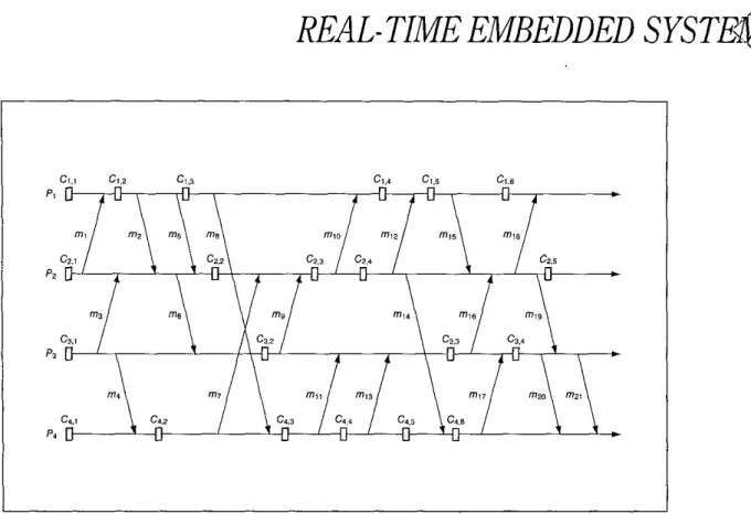
Fig. 5 illustrates an example of the distrihuted computing of a real-time embedded system with a given communication pattern and a predetermined set of basic checkpoints. In the Figure, there are four processes, PI, Pz, P, and P4, with 21 messages mi, mz, 1123, . . ., and mzi passed among them. The short orange bars indicate basic checkpoints. It is easy to see that C Z , ~ 5C1,5. Hence C Z , ~ and Ci.5 cannot be included in the same global consistent checkpoint. Similarly, we have Ci,s%Cz,s, thus Ci.5 and Cz,5 cannot he included in the same global consislent checkpoint either. In fact, Ci.5 is a useless checkpoint in this system. There is a Z-cycle involving a message chain of mi5 and my2 for C I , ~ . Another Z-cycle for C I , ~ includes a sequence of messages mis, mig, m z i , W 7 , mi6 and miz.
There may he more than one Z-cycle associated with a useless checkpoint.
Similarly, Ci,z, C4,3, C4.4, Ci,5, Cz.3 and C3,4 are also useless checkpoints.
In order to eliminate useless checkpoints we need to add extra checkpoints in the processes. These extra checkpoints are called forced checkpoints. It is desirable that the number of forced checkpoints can be made small so that the incurred overhead is reduced.
Prime non-causal intenral IPNCll
As stated above, the interval for taking a forced checkpoint must be part of a Z-cycle. There are two kinds
COMPUTING & CONTROL ENGINEERING JOLIRNAL AUGUST 2002
REAL- TIME EMBEDDED SYSTE'
<
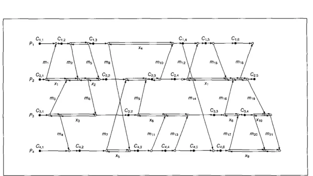
SFig. 6 Distributed computation and a set of prearranged basic checkpoints
of interval in a Z-cycle. Consider some process Pi in the system. Suppose that message ?nX is sent by Pi, and message wy is received by Pi. If we have
&liver(my) &send(m), we call the interval between deliver(my) and send(mx) a causal interval. We call the interval between send(mx) and deliver(my) at Pi a non- causal interval (NCI for short) if send(mx) and deliver(myj are included in the same checkpoint interval, i.e. there exists no checkpoint between send(mx) and deliuer(my) at
Pi. For example, consider the system in Fig. 6. At Pz, the interval between deliver(mz) and send(m6) is a causal interval by definition. The interval between send(mg) and deliver(mi1) at p3 is a non-causal interval by definition, so is the interval between send(mgj and delZve7Q").
However, at P4, the interval between send(mi3) and delzue~m14) is not a non-causal interval because checkpoint C4,5 exists between the two events.
Definition 2 A non-causal interual is called a prime non-causal interval (PNCI j i ~ short) i j Were exists no other send or delivery event in the interval
For example, in the system of Fig. 6, the non-causal interval between sertd(mg) and deliver(mi1) at p3 is a PNCI. However, the non-causal interval betweensend(m9) and deh~er(ml3) is not a PNCIas deliver(mi1) exists in the interval. It is easy to see that any non-causal interval must contain a t least one PNCI. As described previously, any Zkycle includes a t least one non-causal interval.
From our Theorem 1 (details of the theorem can he
found in Reference Z), the problem of placing a minimum number of forced checkpoints to achieve Z-cycle free property can be solved by identifying a proper set of PNCIs in the system.
ldentifiying locations for forced checkpoints
In this section we present an algorithm that identifies the PNCIs where forced checkpoints may be placed to make the system Z-cycle free. Consider a given distributedembedded systemwithNprocessesP1, A,. . ., Pn, and a set p of basic checkpoints. Again, let r p denote the system. Our algorithm is implemented in two steps.
In the first step, we generate a directed graph from rp, which illustrates all possible paths that may be involved in Z-cycles. The original problem is converted to another problem on this directed graph. We then solve the new problem in the second step.
Constructing ZC-digraph
We generate, from rp, a directed graph G( V, E), called the ZC-digraph, to facilitate the identification of Z-cycles in the system. In the following treatment, we only consider the send, the delivery and the checkpoint events.
For rp, the directed graph G is constructed by having each event correspond to a distinct vertex in G. Directed edges in G reflect all possible links that may be included in Z-cycles of the system. Let eij represent thejth event in process Pi. To facilitate our description, the notations for events are also used to represent the corresponding
A
COMPUTING & CONTROL ENGINEERING JOURNAL AUGUST 2002
Fig. 7 ZCdigraph for the system of Fig. 6
vertices in Vof G. The construction of G( V, E, is formally defined as follows:
V = { e i j l e i j i s a n e v e n t i n p r o c e s s P i , f o r a l l l S i ~ N ) A directed edge e i j > E E if any one of the following conditions is met:
-There exists a message VI such that eir = send(m) and
ejJ = deliucr(m)
- i = j and y = x + 1
- i = j , x = y + l , e i J + e p a n d e j J e p.
In the above definition, there are three conditions
specified for the existence of the edges in G. The first two conditions aregiven toreflect message transmissions and causal relations in a process. The third one is used to address the existence of non-causal intervals. In the following treatment, we call edges of this class backward edges, indicating the fact that their directionsareagainst causal directions.
Since no checkpoint may exist in a non-causal interval, no backward edges may direct to or from a checkpoint.
Fig. 7 shows the ZC-digraph for the system of Fig. 6. In the Figure, notations Pi, W , .% and P4 are retained for clarity purpose. Vertices that corresuond to the basic
1 \”
PNCI
computing panern
ZC-digraph
Fig. 8 ZGdigraphs before and after adding forced checkpoint f
checkpoints in !3 are illustrated with filled circles and are labelled in the Figure. Also labelled are edges that represent message transmissions.
The backward edges that correspond to the PNCIs in rp are
labelled by xi, 1 Si< 10. In a ZC- digraph, we define a ZC-cycle as a directed path from a checkpoint vertex to itself.
Consider adding a forced checkpoint to a PNCI in rp. Let this PNCI he the interval between send(mx) and delzuer(mr). The Z C ~ digraph of the resulting system can he obtained by transforming that of
rp as follows: (1) add an extra vertex that corresponds to the added forced checkpoint; (2) remove the backward edge associated with the original PNCI, and (3) replace the original edge from send(mr) to deliuedmy) by
COMPUTING & CONTROL ENGINEERING JOLJRNAL AUGUST 2002
A
two edges, one from seizd(mx) to the forced checkpoint and another from the forced checkpoint to deliuer(n?y).
This transformation is illustrated in Fig. 8. The problem of locating the PNCIs for placing forced checkpoints so that the system may become Z-cycle free is converted to finding places in the corresponding ZC-digraph for performing the aforementioned operations so that the resulting ZC-digraph is free of ZC-cycles.
Problem reduction
There are several observations that are useful for reducing the complexity of the problem. Consider theZC- digraph G(V, E ) of rp. There exists a ZC-cycle for a checkpoint vertex C if and only if the strongly connected component in G that contains C includes more than one vertex. In fact, a strongly connected component that contains a checkpoint vertex Cconsists exactly of all the vertices that are located on some ZC-cycles associated with C. For any checkpoint vertex for which no ZC-cycle exists, the strongly connected component that contains the vertex would he formed entirely by the checkpoint vertex itself.
Henceforth, we first decompose G into its strongly connected components. We ignore those strongly con- nected components that contain a single vertex or contain no checkpoint vertex. No ZC-cycles may possibly exist for vertices in these components. The rest of the strongly connected components are called meaningfui stronglj coizizected componeizts (abbreviated as MSCCs).
There is at least one ZC-cycle associated with each checkpoint vertex in an MSCC. Strongly connected components of G can be found in O( I VIA3) time.4 The original problem is thus divided into several sub- problems, one for each of the MSCCs of G. A solution for the original problem is obtained hy combining the
solutions to all of the suh-prohlems. For example, we obtain three MSCCs for the ZC-digraph of Fig. 9. These MSCCs are illustrated in Fig. 9, in which they are identified as H I , H2 and H3.
Consider an MSCC H( Vh, Eh) of G. We are to find a set of backward edges in Eh, each corresponding to some PNCI of rp, whose removal makes H free of ZC-cycles.
Obviously, it would he desirable to find the minimum number of such edges. This problem can he modelled as a getzemlised lueighted&edback edge set problem, called SUBSET-FES? which is stated as follows: 'Consider a directed graph with weighted edges. A cycle is considered interestipzg if it intersects a subset of special vertices and edges. Find a subset of edges with minimum total weight that intersects every interesting ?ycle in the graph.' Our problem may he transformed to a SUBSET- FES problem by setting the weights of all of the backward edges in E/z that correspond to PNCIs to one and the weights of the rest of the edges to infinity. All the checkpoint vertices in Vk are indicated as the special vertices and there is no special edge. In this case, the interesting cycles correspond to the ZC-cycles in H. A solution for this SUBSET-FES problem directly provides a solution for our problem. The general SUBSET-FES problem is NP~hard with only two special vertices.
An approximation algorithm has been presented in Reference 9. Their polynomial-time approximation factor is O(log2 h), where h is the number of special vertices (checkpoint vertices).
Although we resort to an approximation method to find a near-optimal solution, in general, optimal solutions may he obtained in polynomial time in many cases. If there is only one checkpoint vertex in Vh, we can find the optimal solution using max-flow min-cut algorithm.
Moreover, many MSCCs can be characterised as
H , H2 H,
Fig. 9 MSCCS for the ZC-digraph of Fig. 7
COMPUTING & CONTROL ENGINEERING JOURNAL AUGUST 2002
reducible flow graphs.lu Optimal solutions for reducible flow graphs may also be obtained in polynomial time by using Ramachandran's algorithm.Iu For example, in Fig. 9, the MSCC Hi contains only one checkpoint vertex Ci,z and MSCC Hz is a reducible flow graph. The solutions for the MSCCs Hi, Hz and H3 of Fig. 9 are {xi},
(x4) and (x7, xg}, respectively. All three solutions are optimal in this case.
Minimal solution set
The set of backward edges that are located in the previous step assures that their removal makes the ZC- digraph of the original system r p free of ZC-cycles (with respect to the basic checkpoint vertices). Actually, each of these backward edges corresponds to a forced checkpoint to be inserted. However, the previous operation does not take the existence of ZC-cycles for the vertices that correspond to the forced checkpoints into consideration.
We have to ensure that no new ZC-cycles may be created for the forced checkpoint vertices in the resulting ZC~
digraph. Let Eb represent the set of backward edges located in the previous step for someMSCCH. As shown later, this property can be achieved, for H, as long as the set Eb of backward edges located is minimal in the sense that no proper subset O f E b would satisfy the requirement that the ZC-digraph of remains free of ZC-cycles if the edges of the subset are removed. Apparently, if Eb is a minimum set for H, then Eb is minimal. Suppose that the approximation method3 is used to find Eb; Eb is not guaranteed to be a minimal set. In this case, we may apply a greedy method to the edges in Eb as follows. First
remove all edges in Eb from the ZC-digraph of rp. The resulting graph must be ZC-cycle free. We then take an edge, say eh, from Eb, put the edge back to the graph and examine whether the graph remains ZC-cycle free. If it does, then delete eb from Eb, and go on to the next edge.
We perform this operation for all the edges in Eb, one by one. It is easy to see that Eb finally becomes a minimal set.
Finding the transitive closure of the graph requires examining whether a graph is ZC-cycle free. Forced checkpoints are inserted according to Eb. We conclude this section by proving that no new ZC-cycle would be created for any added Checkpoint vertices as long as the set Eb is minimal.
From our Theorem 3 (details of the theorem can be found in Reference 2) and the fact that noZC-cycles exist for basic checkpoints, the resulting ZC-digraph, with forced checkpoints inserted according to our scheme, is ZC-cycle free. For the previous example of Fig. 9, the sets of backward edges located for the MSCCs H I , Hz and H3 are minimum ones, and hence they are minimal sets. A total of four forced checkpoints should be added at the PNCIs that correspond to the edges labelled by xi, x4, x7 and xg. It is easy to see that the resulting system, which is shown in Fig. 10, is 2-cycle free.
Discussion
In Fig. 11, there are six processes, with some messages passed among them. The short orange bars indicate basic checkpoints and the short blue bars indicate forced checkpoints. Owing to the history of messages m2, m5 and 1123, there is a possibility for a 2-cycle to be formed.
1 0 basic checkpoint I forced checkpoint
Fig. 10 Final system with forced checkpoints added to the original system of Fig. 6
COMPUTING & CONTROL ENGINEERINGJOURNAL AUGUST 2002
REAL- TIME EMBEDDED S Y S T q S /
0 basic checkpoint I forced checkpoint
Fig. 11 Unneeded forced checkpoints
The forced checkpoint Cz is taken because of the suspicion that the basic checkpoint Ci will become use- less according to some existing methods? Unfortunately, it is easy to see that Cz was in a Zcycle (m6 and mz) if C3 wasn't taken. Similarly, C4 is triggered by C3 since C3 was also in aZ-cycle (m4 and m 7 ) without C4. In fact Cz, C3 and C4 are needless checkpoints in this system. Hence, many forced checkpoints not only may be triggered in such suspected situation, but also some of those unnecessary forced checkpoints may become useless checkpoints in the same conditions. The propagation of the needless forced checkpoints is attributed to the incomplete information for detecting 2-cycles. However, in Fig. 11, only the forced checkpoint C5 is necessary. Apparently, it is desirable that the number of forced checkpoints can be made small so that the incurred overhead is reduced.
Consequently, the number of forced checkpoints must be minimal only with our algorithm.
Conclusion
In this paper, we have presented a scheme for placing forced checkpoints in a distributed real-time embedded system so as to make all checkpoints useful for rollback recovery Using the notion of PNCI, we are able to reduce the problem to identifying a set of PNCIs in the system where forced checkpoints should be inserted. An efficient algorithm has been presented in the paper. Although our algorithm offers a near-optimal solution, in general optimal solutions could be obtained in many cases using reduction techniques. Timing constraints are normally imposed upon real~time embedded systems. The addition of the forced checkpoints may possibly result in having some deadlines that are missed. In this case. basic
checkpoints need to be re-scheduled. The efficiency of our algorithm is useful in this regard. Moreover, our scheme is also useful for debugging purposes.
R e t ere n E e s
1 ZUBERI, K. M., and SHIN. K. G.: 'Des@ and implementation of efficient message scheduling for controller area network'. IEEE TC, February ZOOO, 49. (21, pp. 182-188
2 CHIU, J.-E. and CHIU, G.-M.: 'Placing forced checkpoints in distributed real-time embedded systems'. IEEEIEE Real-Time Embedded Systems Workshop London, 3rd December 2001, available at: http:ilrtds.cs.tamu.eduichiu.pdf
3 ELNOZAHY, E. N., JOHNSON, D. B., and WANG, Y. M.: X survey of rollback~reo~wry protocols in message~passing systems'. Technical Report CMU-CS-96~181
4 H E L M , J. M., et 01: 'Communication-based prevention of useles checkpoints in distributed computations'. Lhihibuted Ompztitq, ZMN, 13, (1) pp. 29-43
5 R W A N N A N , D.. and S l N G h U . M.: '2uasi-synchronous check- pointing: models. characterization, and classification', IEEE TPDS, July 1999,1O,l7), pp.703-717
6 CHANDY, K. M., and LAMPORT, L.: 'Distributed snapshots: detrr- mining global states of distributed systems', Communication of ACM, February 1985.3, pp. 63-75
7 ALVEI, I,., ef 01: 'An analysis of communication induced check- painting', E E E ITCS-99 pp. 242~249
8 NETZER. R. H. B., andXU,J.:'Necessary andsufficient conditionsfor mnsistrnt global snapshots'. IEEE TPDS, 1995.6, (Z), pp.165-169 9 E F N , G., NAOR,J., XHIEBER, B.. and SUDAN, M.: 'Approximating
minimum feedback sets and multicuts in diiected e r a o h i . I . Algoritkmiro. 1998.20, pp. 151-174
10 RAMACHANDRAN, \? 'Finding a minimum leedback arc set in reducible flaw graphs'. Jourtiol o/A!gorithms, 1988. pp. 299-313 0 IEE 2002
A
COMPUTING & CONTROL ENGINEERING JOURNAL AUGUST 2002