Efficient Protocol Converter Generation for System Integration
4
0
0
全文
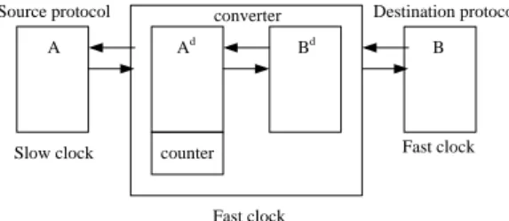
(2) 2010 Asia Pacific Conference on Circuits and Systems (APCCAS 2010) 6 – 9 December 2010, Kuala Lumpur, Malaysia Figure 1 shows that a protocol can be defined as a product set composed of control output space O, control input space I, and a vector D. A vector D has an integer for each data port, and their values reflect the data port conditions such as consuming data (negative), producing data (positive) and neither (zero). The product Σ= I × O × D is called the protocol alphabet. Synchronous protocol can be defined as the subset of Σ* which is the finite strings over the Σ and specifies the initial segment. The finite strings of Σ can be constructed by a deterministic FSA. The source protocol P is represented formally by (1). The destination protocol P’ is represented in the same way, but its components are denoted by single primes. We assume that there is a single data port with the same width between P and P’, so the function d indicates that data port consumes data ( d = (-1) ) or produces data( d = (+1) ). (1) P S , I , O, r s, T , d : I S (2) T ( I S S O) In (1), S is the set of states with the initial state r. I and O are the finite protocol input and output control spaces. T is the set of state transition. i, x, y, o T represents the transition from the current state x to next state y with the input i and output o. Function d reflects the data port conditions such as consuming data (negative), producing data (positive) or neither (zero) and the value of d depends on I and S. Now we have the two protocols P and P’, and then the corresponding product P’’ = P × P’ is defined in (3): P S , I , O, r , T , d ; P ' S ' , I ' , O ' , r ' , T ' , d ' P P' S S ' , I I ' , O O' , r r ' , T ' ' , d ' ' Where T’’ and d’’ is defined as: (i, i ' ), ( s, s ' ), (t , t ' ), (o, o' ) T ' ' d" d d '. (3) (4). In (4), the current state and destination state now are composite states of two protocols and so are control signals. Variables d and d’ represent the status of two connected data ports, so we can consider d’’ as the update of the FIFO between two data ports. When d = (+1) and d’ = (-1), it means that the source protocol produces a data and the destination protocol consumes a data, so the number of the data in FIFO doesn’t change (d’’ = 0). If d = (+1) and d’ = 0, we need FIFO to hold the data temporally until the data is consumed. The converter synthesis algorithm can be briefly described as following steps: Step 1: Make states whose transitions all violate the data path constraints dead. It’s also necessary to remove the transitions that violate the data path constraints in the states that are not dead. Step2: Make the transitions dead if the transitions lead to the dead state. Because we make some transitions dead, there would be new dead states. When a state doesn’t have any legal transition from itself, we should remove this state to prevent the occurrence of deadlock. Step 3: Repeat Step 2 until the dead state set does not change and get a pruned product P 0 ” by removing the dead state set from the P’’. Step 4: Resolve the output non-determinitism in P 0 ” according to data transaction condition. A deterministic P d ” generated after this step. Step 5: Translate the P d ” into FSM. The data path constraints are an important idea to guide the algorithm to get a corrected converter. We can see that this concept also appeared in [7] and [9], the constraints make the converter avoid overflow or underflow.. B. Two Protocols Operating at Different Frequencies In [10], the authors proposed an approach to covert two protocols operating at different clock domains. The main idea is based on the relation of the frequencies between two protocols. Assume that the source protocol operates at the clock frequency f s and the destination protocol operates at the clock frequency f d . In the following, the situation will be classified into two cases according to the value of f d /f s . Source protocol. Destination protocol. converter. A. Ad. Bd. Slow clock. counter. B. Fast clock. Fast clock. Fig. 2 Protocol Converter between Protocols Operating at Different Clock Domains.. In case I that f d /f s is an integer number, we can rewrite the equation as f d =n×f s . The protocol converter should operate at higher clock frequency, otherwise the protocol converter would loss information from the destination protocol. Before starting the synthesis, states and edges would be modified. A frequency matching counter which counts from 0 to (n-1)=(f d /f s )-1 is inserted to avoid faster one sampling the signals of slower one twice. In case II that f d /f s is not an integer number, one of the solutions is to find the LCM (least common multiplier) of both clock frequencies since a real number can be represented as a ratio of two integers. Then the protocol converter can be set to operate at the frequency of the LCM and synthesized as the steps of case I with two frequency matching counters. We should notice that a large LCM would cause area overhead in this method.. III. PROPOSED CONVERTER SYNTHESIS FLOW A. Deterministic Input Format with Constraints In comparison with [8], the inputs of the proposed synthesis algorithm are deterministic FSM and there is no non-deterministic intermediate FSM. For this reason, we don’t need a non-deterministic solver in our synthesis algorithm. By adding constraint variable as the inputs of FSM, we can get additional information for FSM to make transitions deterministic. In this generator, we provide full and empty with different levels for users. When using user-defined variables, user should design the logic behavior in the RTL code generated by the protocol converter synthesizer. Example: Assume that the destination protocol is a master on the bus, and the master can decide to send request to the bus or keep idle. The two choices can’t be deterministic by the information from the bus to the master in the specific state. In fact, this decision should be dependent on the internal information about the status of the FIFO. The master should send a request to the bus when there are data which are ready to be transferred in the FIFO. By using the empty status of data FIFO, converters can decide if the master can send a request to the bus when the data FIFO is not empty. If a non-deterministic transition is not a necessary transition, we can just remove it. Example: Assume that the destination protocol is a master on the bus, and the master can decide to send serial simple transfers or a burst transfer. The two choices can’t be deterministic by the information from the bus to the master in the specific state. If the burst transfer is necessary, constraint variables should be applied..
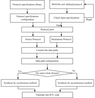
(3) 2010 Asia Pacific Conference on Circuits and Systems (APCCAS 2010) 6 – 9 December 2010, Kuala Lumpur, Malaysia Otherwise, the burst transition can be removed to make FSM deterministic.. B. Input Format Checker Title must be in 24 pt Regular font. Author name must be in 11 pt Regular font. Author affiliation must be in 10 pt Italic. Email address must be in 9 pt Courier Regular font.. to determine the status of the FIFO, and use the handshake mechanism to get information cross two clock domains. And replace the tri-buffer by multiplexers, because it may cause the leakage current. This architecture is highly scalable and the width of the data item can be changed with very few design modifications.. Fig. 4 Handshaking FIFO Architecture prst_n_o. put_interface_cell. preq_i pdata_i pen_i pclk ptok_o. Data reg Handshake. Handshake. Handshake. Handshake. get_interface_cell. gtok_o gclk. Fig. 3 Flow of Protocol Converter Generation gen_i. Figure 3 shows the flow of protocol converter generation without a non-deterministic solver which reduces the protocol synthesis time significantly. There are several build in protocol specifications such as APB, AHB, AXI and OCP in our library. Users can select one of the protocols, and our program will load the corresponding protocol specification and provide configurable options. These protocol specifications are all checked by the input-format checker to avoid non-deterministic transitions and contain optimized constraints in the FSM. It is also available for users to build the protocol which is not defined in our library, but the protocol specifications defined by users should also be checked by our input-format checker. In the synthesis flow, we will check the FIFO constraint and remove the edges that violate the FIFO constraint to avoid overflow or underflow. After building the FSM of converter by the program, check if there are states that don’t have any transitions from themselves and remove these states. The transitions that go to these states should also be deleted. The step that prunes the states and transitions would be repeated until no more state and transition can be purged. After pruning the FSM, the program will check if there is any strong-connected component (SCC) that doesn’t contain initial state. Because the SCCs without an initial state mean that these states will never be reached.. C. Handshaking FIFO Design As two protocols operate at different frequencies, the previous described method can’t handle the phase drift due to the manufacture. Moreover the performance decreases significantly when the LCM of frequencies in two protocols is too large. In order to solve these problems efficiently, we use the handshaking FIFO to handle asynchronous signals. The FIFO architecture is shown in Figure 4. This architecture is a modified from [11]. We remove the asynchronous circuit that is used. gset_n_o. pvalid_o. gdata_i. Fig. 5 Implementation of put and get interface cell. The put interface contains a Full detector and put_interface_cells and the get interface contains an Empty detector and get_interface_cells. The communication between two interfaces should be synchronized by the Sync module. Each interface module only operates at one clock domain and can be synthesized separately. When preq_i is active, the data will be putted into FIFO and the number of counters in the Full detector will be added a number that can reflect the proportion of the data widths in two protocols. If the get interface sends the message of getting data from FIFO through the handshaking mechanism, the number of counters in the Full detector will be subtracted a corresponding number. However there are latencies caused by the synchronization and handshaking when sending messages from the get interface to the put interface. The number of counters in the Full detector can’t represent the exact status of FIFO, but the most important point is that the converter avoids overflow by waiting the message from the get interface. Empty detector uses the same idea to provide a conservative status, and converter can avoid underflow by checking the conservative status of FIFO. Figure 5 shows the implementation of the put_interface_cell and the get_interface_cell, each cell of two interfaces contains a token and data registers. When the cell gets a token, it means that data will be stored in this data register or fetched from this data register. We can see that a data register doesn’t pass through the synchronizer, because synchronization of the data bus can be handled by using the handshaking latency. When the get interface got the information that data was ready for fetching, the latency at least two put clock periods.
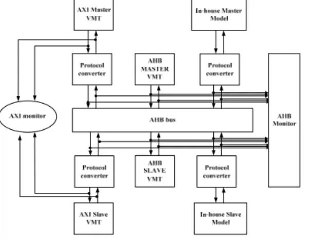
(4) 2010 Asia Pacific Conference on Circuits and Systems (APCCAS 2010) 6 – 9 December 2010, Kuala Lumpur, Malaysia and two get clock periods has been passed. In general, all the bits of the data bus were already stable for fetching. We can also increase the number of synchronization stages in handshake module to get more confidence for stable data.. IV. VERIFICATIONS AND EXPERIMENT RESULTS We verify the converter results by Synopsys DesignWare VIP. In the VIP environment, the Vera Modeling Technology (VMT) models are provided for establishing of the whole system simulation environment including the virtual master, virtual arbiter and so on. We can use the commands in the test bench to control the behavior of all models according to [12]. In this experiment, we want to plug the SRAM with an AXI slave interface to the AHB bus. In other words, we want to use an AHB slave as the source protocol and an AXI slave as the destination protocol to synthesis the protocol converter. After we define all necessary information for our tool, we can start to synthesize the protocol converter between AHB slave and AXI slave. By adding our converter and the AXI agent, the verification work can be started.. the VIP to check the AHB interface and AXI interface if behaviors of all signals are compliant to the specification. The transaction mode coverage information is also checked. We compare our converter synthesis results with the AHB-to-AXI wrapper which is supplied by ARM PrimeCell [13] in Table 1. Adopting protocol constraints has contributed to the pipeline transaction supporting. The area of the generated converter is more than the wrapper supplied by ARM PrimeCell. The reason is that the generated converter here has additional storage interfaces to communicate with the controller, so the overhead of the area would be near constant as the FIFO length increasing. In order to compare with PrimeCell, the technology used here was TSMC 0.13um process, slow operating condition.. V. CONCLUSIONS We have presented an efficient protocol synthesis flow based on the deterministic input FSM with constraints. The proposed method reduces the converter synthesis time. Furthermore, by employing a variety of constraints in the input FSM the generated protocol converter can achieve low area and high performance. The experimental result shows that the generated protocol converter is almost as efficient as the manual one. Moreover a reliable handshaking FIFO interface are proposed to dear with IP’s operating at different clock domains.. REFERENCES [1]. [2] [3] [4] Fig. 6 Converter Verification Environment [5] TABLE I SYNTHESIS RESULT COMPARE TO ARM PRIME CELL. Our converter PrimeCell [13] 32-bit 32-bit Pipeline Single active transaction 1 Latency overhead 1 Latency overhead Fixed-length AHB bursts are converted into AXI bursts. Undefined-length bursts are converted into single transfers. AXI slave accepts data/response with zero wait states. Unused signals are tied low. Converter controller Approximately 1.2k gates 0.56k gates 200 MHz Area of 32-bit D flipflop : 0.26k gates Total area 1.86k gates 200 MHz Figure 6 shows the environment for the verification of generated converter from our EDA tool. We use an AHB master model to initiate transactions to the converter which wraps the AXI slave. By using the AXI monitor and the AHB monitor, we can make sure both protocol interfaces of the converter can work correctly. We sent all transactions which are available in the AHB master to the converter to check if our converter can give right response to AHB and to translate the AHB transactions into AXI transactions. Then we use. [6]. [7]. [8]. [9]. [10]. [11]. [12] [13]. J. Akella and K. McMillan, “Synthesizing Converter between Finite State Protocols,” in Proc. Int. Conf. Comput. Design, pp.410-413, Oct. 1991. P. E. Green, Jr., “Protocol conversion,” IEEE Trans. Commun., vol. COM-34, pp.257-168, Mar. 1986. K. L. Calvert and S. S. Lam, “Formal Method for Protocol Conversion,” IEEE Trans. Commun., vol. 8, pp.127-168, Jan. 1990. S. S. Lam, “Protocol conversion,” IEEE Trans. Software Eng., vol. 14, pp. 353-362, Mar. 1988. K. Okumura, “A formal protocol conversion method,” in Proc. ACM Conf. on Communications architectures and protocols, pp.30-37, Aug. 1986. V. D’silva, S. Ramesh, and A. Sowmya, “Synchronous Protocol Automata: a framework for modeling and verification of SoC communication architecture,” in Proc. Design, Autom. Test Eur, pp.390-395, Feb. 2004. R. Passerone, J. A. Rowson, and A. Sangiovanni-Vincentelli, “Automatic Synthesis of Interfaces between Incompatible Protocols,” in Proc. Eur. Conf. Design Automat., pp.8-13, Jun. 1998. V. Androutsopoulos, D.M. Brookes, and T.J.W. Clarke, “Protocol Converter synthesis,” IET Comp. Digit. Tech., vol.1, pp.217-229, Nov. 2004. Y.W. Yao, W.S. Chen, and M.T. Liu, “A Modular Approach to Constructing Protocol Converters*,” in Proc Int. Conf. Computer Communications, pp.572-579, Jun. 1990. B. Park, H. Choi, and C. M. Kyung, “Synthesis and Optimization of Interface Hardware between IP’s Operating at Different Clock Frequencies,” in Proc. Int. Conf. Comput. Design, pp.519-524, Sept. 2000. T. Chelcea and S.M. Nowak, "Robust interfaces for mixed-timing systems," IEEE Trans. VLSI Syst., vol. 12, no. 8, pp. 857-873, Aug. 2004. Synopsys, DesignWare AHB Verification IP Databook. 2006. ARM, PrimeCell Infrastructure AMBA2 AHB to AMBA3 AXI Bridges, Rev. r0p1. Feb. 2006..
(5)
數據
相關文件
– The distribution tells us more about the data, including how confident the system has about its including how confident the system has about its prediction. It can
For a directed graphical model, we need to specify the conditional probability distribution (CPD) at each node.. • If the variables are discrete, it can be represented as a
With λ selected by the universal rule, our stochastic volatility model (1)–(3) can be seen as a functional data generating process in the sense that it leads to an estimated
This research is to integrate PID type fuzzy controller with the Dynamic Sliding Mode Control (DSMC) to make the system more robust to the dead-band as well as the hysteresis
In order to use the solar rays more efficient and improve the conversion efficiency of solar cell, it is necessary to use antireflection layer to reduce the losses of
This thesis makes use of analog-to-digital converter and FPGA to carry out the IF signal capture system that can be applied to a Digital Video Broadcasting - Terrestrial (DVB-T)
It allows a much wider range of algorithms to be applied to the input data and can avoid problems such as the build-up of noise and signal distortion during processing.. Since
Furthermore, given a set of nets in a bus on routing grids with obstacles, and the length constraints for all the nets in the bus, based on this proposed longest path generation,
