MOTION CONTROLLER (SV13/22) (REAL MODE)
Programming Manual
type A173UHCPU, A273UHCPU
MOTION CONTROLLER(SV13/22) (REAL MODE) Programming Manual, type A173UHCP,A273UHCPU
INTORODUCTION
Thank you for purchasing the Mitsubishi Motion Controller/Personal Machine Controller. This instruction manual describes the handling and precautions of this unit. Incorrect handing will lead to unforeseen events, so we ask that you please read this manual thoroughly and use the unit correctly.
Please make sure that this manual is delivered to the final user of the unit and that it is stored for future reference.
Precautions for Safety
Please read this instruction manual and enclosed documents before starting installation, opera- tion, maintenance or inspections to ensure correct usage. Thoroughly understand the machine, safety information and precautions before starting operation.
The safety precautions are ranked as "Warning" and "Caution" in this instruction manual.
WARNING
When a dangerous situation may occur if handling is mistaken leading to fatal or major injuries.CAUTION
When a dangerous situation may occur if handling is mistaken leading to medium or minor injuries, or physical damage.Note that some items described as cautions may lead to major results depending on the situation. In any case, important information that must be observed is described.
For Sate Operations
1. Prevention of electric shocks
WARNING
Never open the front case or terminal covers while the power is ON or the unit is running, as this may lead to electric shocks.
Never run the unit with the front case or terminal cover removed. The high voltage terminal and charged sections will be exposed and may lead to electric shocks.
Never open the front case or terminal cover at times other than wiring work or periodic inspections even if the power is OFF. The insides of the control unit and servo amplifier are charged and may lead to electric shocks.
When performing wiring work or inspections, turn the power OFF, wait at least ten minutes, and then check the voltage with a tester, etc. Failing to do so may lead to electric shocks.
Always ground the control unit, servo amplifier and servomotor with Class 3 grounding. Do not ground commonly with other devices.
The wiring work and inspections must be done by a qualified technician.
Wire the units after installing the control unit, servo amplifier and servomotor. Failing to do so may lead to electric shocks or damage.
Never operate the switches with wet hands, as this may lead to electric shocks.
Do not damage, apply excessive stress, place heavy things on or sandwich the cables, as this may lead to electric shocks.
Do not touch the control unit, servo amplifier or servomotor terminal blocks while the power is ON, as this may lead to electric shocks.
Do not touch the internal power supply, internal grounding or signal wires of the control unit and servo amplifier, as this may lead to electric shocks.
2. For fire prevention
CAUTION
Install the control unit, servo amplifier, servomotor and regenerative resistor on inflammable material. Direct installation on flammable material or near flammable material may lead to fires.
If a fault occurs in the control unit or servo amplifier, shut the power OFF at the servo amplifier's power source. If a large current continues to flow, fires may occur.
When using a regenerative resistor, shut the power OFF with an error signal. The regenera- tive resistor may abnormally overheat due to a fault in the regenerative transistor, etc., and may lead to fires.
Always take heat measures such as flame proofing for the inside of the control panel where the servo amplifier or regenerative resistor is installed and for the wires used. Failing to do so may lead to fires.
3. For injury prevention
CAUTION
Do not apply a voltage other than that specified in user's manual, or the instruction manual for the product you are using on any terminal. Doing so may lead to destruction or damage.
Do not mistake the terminal connections, as this may lead to destruction or damage.
Do not mistake the polarity (+/−), as this may lead to destruction or damage.
The servo amplifier's heat radiating fins, regenerative resistor and servo amplifier, etc., will be hot while the power is ON and for a short time after the power is turned OFF. Do not touch these parts as doing so may lead to burns.
Always turn the power OFF before touching the servomotor shaft or coupled machines, as these parts may lead to injuries.
Do not go near the machine during test operations or during operations such as teaching.
Doing so may lead to injuries.
4. Various precautions
Strictly observe the following precautions.
Mistaken handling of the unit may lead to faults, injuries or electric shocks.
(1) System structure
CAUTION
Always install a leakage breaker on the control unit and servo amplifier power source.
If installation of a magnetic contactor for power shut off during an error, etc., is specified in the instruction manual for the servo amplifier, etc., always install the magnetic contactor.
Install an external emergency stop circuit so that the operation can be stopped immediately and the power shut off.
Use the control unit, servo amplifier, servomotor and regenerative resistor with the combi- nations listed in the instruction manual. Other combinations may lead to fires or faults.
If safety standards (ex., robot safety rules, etc.,) apply to the system using the control unit, servo amplifier and servomotor, make sure that the safety standards are satisfied.
If the operation during a control unit or servo amplifier error and the safety direction operation of the control unit differ, construct a countermeasure circuit externally of the control unit and servo amplifier.
In systems where coasting of the servomotor will be a problem during emergency stop, servo OFF or when the power is shut OFF, use dynamic brakes.
Make sure that the system considers the coasting amount even when using dynamic brakes.
In systems where perpendicular shaft dropping may be a problem during emergency stop, servo OFF or when the power is shut OFF, use both dynamic brakes and magnetic brakes.
The dynamic brakes must be used only during emergency stop and errors where servo OFF occurs. These brakes must not be used for normal braking.
The brakes (magnetic brakes) assembled into the servomotor are for holding applications,
CAUTION
Use wires and cables that have a wire diameter, heat resistance and bending resistance compatible with the system.
Use wires and cables within the length of the range described in the instruction manual.
The ratings and characteristics of the system parts (other than control unit, servo amplifier, servomotor) must be compatible with the control unit, servo amplifier and servomotor.
Install a cover on the shaft so that the rotary parts of the servomotor are not touched during operation.
There may be some cases where holding by the magnetic brakes is not possible due to the life or mechanical structure (when the ball screw and servomotor are connected with a timing belt, etc.). Install a stopping device to ensure safety on the machine side.
(2) Parameter settings and programming
CAUTION
Set the parameter values to those that are compatible with the control unit, servo amplifier, servomotor and regenerative resistor model and the system application. The protective functions may not function if the settings are incorrect.
The regenerative resistor model and capacity parameters must be set to values that conform to the operation mode, servo amplifier and servo power unit. The protective functions may not function if the settings are incorrect.
Set the mechanical brake output and dynamic brake output validity parameters to values that are compatible with the system application. The protective functions may not function if the settings are incorrect.
Set the stroke limit input validity parameter to a value that is compatible with the system application. The protective functions may not function if the setting is incorrect.
Set the servomotor encoder type (increment, absolute position type, etc.) parameter to a value that is compatible with the system application. The protective functions may not function if the setting is incorrect.
Set the servomotor capacity and type (standard, low-inertia, flat, etc.) parameter to values that are compatible with the system application. The protective functions may not function if the settings are incorrect.
Set the servo amplifier capacity and type parameters to values that are compatible with the system application. The protective functions may not function if the settings are incorrect.
Use the program commands for the program with the conditions specified in the instruction manual.
Set the sequence function program capacity setting, device capacity, latch validity range, I/O assignment setting, and validity of continuous operation during error detection to values that are compatible with the system application. The protective functions may not function if the settings are incorrect.
Some devices used in the program have fixed applications, so use these with the conditions specified in the instruction manual.
The input devices and data registers assigned to the link will hold the data previous to when communication is terminated by an error, etc. Thus, an error correspondence interlock program specified in the instruction manual must be used.
Use the interlock program specified in the special function unit's instruction manual for the program corresponding to the special function unit.
(3) Transportation and installation
CAUTION
Transport the product with the correct method according to the weight.
Use the servomotor suspension bolts only for the transportation of the servomotor. Do not transport the servomotor with machine installed on it.
Do not stack products past the limit.
When transporting the control unit or servo amplifier, never hold the connected wires or cables.
When transporting the servomotor, never hold the cables, shaft or detector.
When transporting the control unit or servo amplifier, never hold the front case as it may fall off.
When transporting, installing or removing the control unit or servo amplifier, never hold the edges.
Install the unit according to user's manual, or the instruction manual for the product you are using in a place where the weight can be withstood.
Do not get on or place heavy objects on the product.
Always observe the installation direction.
Keep the designated clearance between the control unit or servo amplifier and control panel inner surface or the control unit and servo amplifier, control unit or servo amplifier and other devices.
Do not install or operate control units, servo amplifiers or servomotors that are damaged or that have missing parts.
Do not block the intake/outtake ports of the servomotor with cooling fan.
Do not allow conductive matter such as screw or cutting chips or combustible matter such as oil enter the control unit, servo amplifier or servomotor.
The control unit, servo amplifier and servomotor are precision machines, so do not drop or apply strong impacts on them.
Securely fix the control unit and servo amplifier to the machine according to the instruction manual. If the fixing is insufficient, these may come off during operation.
Always install the servomotor with reduction gears in the designated direction. Failing to do so may lead to oil leaks.
Store and use the unit in the following environmental conditions.
Conditions Environment
Control unit/servo amplifier Servomotor Ambient
temperature
0°C to +55°C (With no freezing)
0°C to +40°C (With no freezing) Ambient humidity According to each instruction
manual.
80%RH or less (With no dew condensation) Storage
temperature
According to each instruction
manual. −20°C to +65°C
Atmosphere Indoors (where not subject to direct sunlight).
No corrosive gases, flammable gases, oil mist or dust must exist.
CAUTION
When coupling with the synchronization encoder or servomotor shaft end, do not apply impact such as by hitting with a hammer. Doing so may lead to detector damage.
Do not apply a load larger than the tolerable load onto the servomotor shaft. Doing so may lead to shaft breakage.
When not using the unit for a long time, disconnect the power line from the control unit or servo amplifier.
Place the control unit and servo amplifier in static electricity preventing vinyl bags and store.
When storing for a long time, contact the Service Center or Service Station.
(4) Wiring
CAUTION
Correctly and securely wire the wires. Reconfirm the connections for mistakes and the terminal screws for tightness after wiring. Failing to do so may lead to run away of the servomotor.
After wiring, install the protective covers such as the terminal covers to the original positions.
Do not install a phase advancing capacitor, surge absorber or radio noise filter (option FR- BIF) on the output side of the servo amplifier.
Correctly connect the output side (terminals U, V, W). Incorrect connections will lead the servomotor to operate abnormally.
Do not connect a commercial power supply to the servomotor, as this may lead to trouble.
Do not mistake the direction of the surge absorbing diode installed on the DC relay for the control signal output of brake signals, etc. Incorrect installation may lead to signals not being output when trouble occurs or the protective functions not functioning.
Do not connect or disconnect the connection cables between each unit, the encoder cable or sequence ex- pansion cable while the power is ON.
Servo amplifier VIN (24VDC)
Control output
signal RA
Securely tighten the cable connector fixing screws and fixing mechanisms. Insufficient fixing may lead to the cables combing off during operation.
Do not bundle the power line or cables.
(5) Trial operation and adjustment
CAUTION
Confirm and adjust the program and each parameter before operation. Unpredictable movements may occur depending on the machine.
Extreme adjustments and changes may lead to unstable operation, so never make them.
When using the absolute position system function, on starting up, and when the controller or absolute value motor has been replaced, always perform a home position return.
(6) Usage methods
CAUTION
Immediately turn OFF the power if smoke, abnormal sounds or odors are emitted from the control unit, servo amplifier or servomotor.
Always execute a test operation before starting actual operations after the program or parameters have been changed or after maintenance and inspection.
The units must be disassembled and repaired by a qualified technician.
Do not make any modifications to the unit.
Keep the effect or magnetic obstacles to a minimum by installing a noise filter or by using wire shields, etc. Magnetic obstacles may affect the electronic devices used near the control unit or servo amplifier.
Use the units with the following conditions.
Item Conditions
Input power According to the separate instruction manual.
Input frequency According to the separate instruction manual.
Tolerable momentary
power failure According to the separate instruction manual.
(7) Remedies for errors
CAUTION
If an error occurs in the self diagnosis of the control unit or servo amplifier, confirm the check details according to the instruction manual, and restore the operation.
If a dangerous state is predicted in case of a power failure or product failure, use a servomotor with magnetic brakes or install a brake mechanism externally.
Use a double circuit construction so that the magnetic brake operation circuit can be operated by emergency stop signals set externally.
If an error occurs, remove the cause, secure the safety and then resume operation.
The unit may suddenly resume operation after a power failure is restored, so do not go near the machine. (Design the machine so that personal safety can be ensured even if the machine restarts suddenly.)
Shut off with servo ON signal OFF, alarm, magnetic brake signal.
Servo motor
Magnetic brakes
RA1 EMG
24VDC Shut off with the emergency stop signal(EMG).
(8) Maintenance, inspection and part replacement CAUTION
Perform the daily and periodic inspections according to the instruction manual.
CAUTION
Do not touch the lead sections such as ICs or the connector contacts.
Do not place the control unit or servo amplifier on metal that may cause a power leakage or wood, plastic or vinyl that may cause static electricity buildup.
Do not perform a megger test (insulation resistance measurement) during inspection.
When replacing the control unit or servo amplifier, always set the new unit settings correctly.
When the controller or absolute value motor has been replaced, carry out a home position return operation using one of the following methods, otherwise position displacement could occur.
1) After writing the servo data to the PC using peripheral device software, switch on the power again, then perform a home position return operation.
2) Using the backup function of the peripheral device software, load the data backed up before replacement.
After maintenance and inspections are completed, confirm that the position detection of the absolute position detector function is correct.
Do not short circuit, charge, overheat, incinerate or disassemble the batteries.
The electrolytic capacitor will generate gas during a fault, so do not place your face near the control unit or servo amplifier.
The electrolytic capacitor and fan will deteriorate. Periodically change these to prevent secondary damage from faults. Replacements can be made by the Service Center or Service Station.
(9) Disposal
CAUTION
Dispose of this unit as general industrial waste.
Do not disassemble the control unit, servo amplifier or servomotor parts.
Dispose of the battery according to local laws and regulations.
(10) General cautions
CAUTION
All drawings provided in the instruction manual show the state with the covers and safety partitions removed to explain detailed sections. When operating the product, always return the covers and partitions to the designated positions, and operate according to the
instruction manual.
Revisions
The manual number is given on the bottom left of the back cover.
Print Date Manual Number Revision
Jan., 2001 IB(NA)-0300028-A First edition
CONTENTS
1. GENERAL DESCRIPTION ...1- 1 to 1-13 1.1 System Configuration ... 1- 3 1.1.1 A273UHCPU System overall configuration ... 1- 3 1.1.2 A173UHCPU(-S1) System overall configuration ... 1- 4 1.2 Table of Software Package ... 1- 5 1.3 Positioning Control by the Servo System CPU ... 1- 6 2. PERFORMANCE SPECIFICATIONS ...2- 1 to 2- 4 2.1 SCPU Performance Specifications ... 2- 1 2.2 PCPU Performance Specifications ... 2- 3 3. POSITIONING SIGNALS...3- 1 to 3-54 3.1 Internal Relays ... 3- 2 3.1.1 Axis status ... 3- 7 3.1.2 Axis command signals... 3-16 3.1.3 Common Device ... 3-22 3.2 Data Registers ... 3-33 3.2.1 Monitoring data area... 3-36 3.2.2 Control change registers ... 3-41 3.2.3 Common devices... 3-42 3.3 Special Relays (SP.M) ... 3-48 3.4 Special Register (SP.D) ... 3-51 4. PARAMETERS FOR POSITIONING CONTROL ...4- 1 to 4-25 4.1 System Settings ... 4- 1 4.2 Fixed Parameters... 4- 2
4.2.1 Setting the number of pulses per revolution / travel value per revolution /
unit magnification... 4- 3 4.2.2 Upper stroke limit value/lower stroke limit value ... 4- 5 4.2.3 Command in-position range ... 4- 6 4.3 Servo Parameters ... 4- 6 4.3.1 Servo parameters of ADU (only when A273UHCPU is used) ... 4- 7 4.3.2 MR- -B servo parameters ... 4- 9 4.3.3 Position control gain 1, 2 ... 4-14 4.3.4 Position control gain 1, 2 ... 4-15 4.3.5 Speed integral compensation ... 4-15 4.3.6 In-position range... 4-16 4.3.7 Feed forward gain... 4-16 4.3.8 Load inertia ratio ... 4-16 4.3.9 Automatic tuning... 4-16 4.3.10 Servo responsiveness setting... 4-17 4.3.11 Notch filter ... 4-18 4.3.12 Electromagnetic brake sequence ... 4-18 4.3.13 Monitor output mode... 4-18
4.3.15 Optional function 2 (no-motor operation selection) ... 4-19 4.3.16 Monitor output 1, 2 offset... 4-20 4.3.17 Pre-alarm data selection... 4-20 4.3.18 Zero speed ... 4-21 4.3.19 Excessive error alarm level ... 4-21 4.3.20 Optional function 5... 4-21 4.3.21 PI-PID switching position droop... 4-21 4.3.22 Torque control compensation factor... 4-21 4.3.23 Speed differential compensation ... 4-21 4.4 Parameter Block... 4-22
4.4.1 Relationships among the speed limit value, acceleration time, deceleration time, and
rapid stop deceleration time ... 4-24 4.4.2 S-curve ratio ... 4-24 4.4.3 Allowable error range for circular interpolation ... 4-25 5. SEQUENCE PROGRAMS AND SFC PROGRAMS...5- 1 to 5-20 5.1 Cautions on Creating a Sequence Program or SFC Program ... 5- 1 5.2 Servo Program Start Request Instruction (SVST) ... 5- 2 5.2.1 Start request instruction for 1 to 32 axes (SVST)... 5- 2 5.3 Current Value Change Instructions (CHGA) ... 5- 5 5.3.1 CHGA instructions ... 5- 5 5.4 Speed Change Instructions (CHGV) ... 5- 8 5.4.1 CHGV instructions ... 5- 8 5.5 Retracing during Positioning ... 5-11 5.6 Torque Limit Value Change Request (CHGT) ... 5-14 5.6.1 CHGT instructions ... 5-14 5.7 SFC Programs ... 5-16 5.7.1 Starting and stopping SFC programs ... 5-16 5.7.2 Servo program start request... 5-17 6. SERVO PROGRAMS FOR POSITIONING CONTROL ...6- 1 to 6-17 6.1 Servo Program Composition and Area ... 6- 1 6.1.1 Servo program composition ... 6- 1 6.1.2 Servo program area... 6- 2 6.2 Servo Instructions ... 6- 3 6.3 Positioning Data ... 6- 9 6.4 Method for Setting Positioning Data... 6-13 6.4.1 Setting by designating numerical values ... 6-13 6.4.2 Setting by using word devices (D, W)... 6-14 6.5 Creating Sequence Programs to Start Servo Programs ... 6-15 6.5.1 Case where the servo program is executed once only... 6-15 6.5.2 Case where different servo programs are executed consecutively... 6-16 6.5.3 Case where the same servo program is executed repeatedly ... 6-17 7. POSITIONING CONTROL...7- 1 to 7-150
7.1.3 Control units for 1-axis positioning control... 7- 7 7.1.4 Control units for interpolation control... 7- 7 7.1.5 Control using degrees as control units ... 7- 9 7.1.6 Stop processing and restarting after a stop... 7-11 7.1.7 Acceleration and deceleration processing... 7-17 7.2 1-Axis Linear Positioning Control ... 7-19 7.3 2-Axes Linear Interpolation Control... 7-23 7.4 3-Axes Linear Interpolation Control... 7-27 7.5 4-Axes Linear Interpolation Control... 7-32 7.6 Circular Interpolation Using Auxiliary Point Designation ... 7-36 7.7 Circular Interpolation Using Radius Designation... 7-40 7.8 Circular Interpolation Using Center Point Designation ... 7-46 7.9 1-Axis Fixed-Pitch Feed Control ... 7-51 7.10 Fixed-Pitch Feed Control Using 2-Axes Linear Interpolation ... 7-54 7.11 Fixed-Pitch Feed Control Using 3-Axes Linear Interpolation ... 7-57 7.12 Speed Control (I) ... 7-60 7.13 Speed Control (II) ... 7-64 7.14 Speed/Position Switching Control ... 7-67 7.14.1 Starting speed/position switching control ... 7-67 7.14.2 Restarting speed/position switching control ... 7-75 7.15 Speed-Switching Control... 7-80 7.15.1 Starting speed-switching control, speed-switching points, end designation... 7-80 7.15.2 Setting speed-switching points using repeat instructions ... 7-86 7.16 Constant-Speed Control... 7-91 7.16.1 Setting Pass points using Repeated Instructions ... 7-95 7.16.2 Speed switching during instruction execution... 7-100 7.16.3 1-axis constant-speed control ... 7-104 7.16.4 2 to 4-axes constant-speed control ... 7-108 7.16.5 Pass point skip function... 7-115 7.16.6 FIN signal wait function ... 7-117 7.17 Position Follow-Up Control... 7-119 7.18 Simultaneous Start ... 7-123 7.19 JOG Operation ... 7-126 7.19.1 JOG operation data ... 7-126 7.19.2 Individual start ... 7-127 7.19.3 Simultaneous start... 7-131 7.20 Manual Pulse Generator Operation ... 7-134 7.21 Home Position Return ... 7-141 7.21.1 Zeroing data ... 7-141 7.21.2 Zeroing by the proximity dog method ... 7-143 7.21.3 Zeroing by the count method... 7-145 7.21.4 Zeroing by the data set method... 7-146 7.21.5 Zeroing servo program ... 7-147 7.22 High-Speed Oscillation... 7-149 8. AUXILIARY AND APPLIED FUNCTIONS ...8- 1 to 8-20 8.1 Limit Switch Output Function ... 8- 2 8.1.1 Limit switch output data ... 8- 2
8.2 M-Code Output Function ... 8- 4 8.3 Backlash Compensation Function... 8- 6 8.4 Torque Limit Function ... 8- 8 8.5 Electronic Gear Function... 8-10 8.6 Absolute Positioning System ... 8-12 8.7 Skip Function ... 8-15 8.8 Teaching Function... 8-16 8.9 High−Speed Reading of Designated Data ... 8-16 8.10 Servo Program Cancel/Start Function ... 8-17 8.11 Enhanced Current Value Control ... 8-19 APPENDICES ... APP- 1 to APP-71 APPENDIX1 SCPU ERROR CODE LIST ... APP- 1 1.1 SCPU Error Code List ... APP- 1 APPENDIX2 ERROR CODES STORED BY THE PCPU ... APP- 5 2.1 Servo Program Setting Errors (Stored in D9190) ... APP- 7 2.2 Minor Errors... APP-10 2.3 Major Errors... APP-17 2.4 Servo Errors ... APP-21 2.5 PC Link Communication Errors ... APP-35 2.6 LED Indications when Errors Occur at the PCPU ... APP-36 APPENDIX3 SPECIAL RELAYS AND SPECIAL REGISTERS ... APP-38 3.1 Special Relays (SP, M)... APP-38 3.2 Special Registers (SP.D)... APP-43 APPENDIX4 EXAMPLE PROGRAMS ... APP-53 4.1 Reading M-Codes... APP-53 4.2 Error Code Reading... APP-54 4.3 Magnitude Comparison and Four Fundamental Operations of 32-Bit Monitor Data ... APP-55 APPENDIX 5 SETTING RANGE OF INDIRECTLY DESIGNATED DEVICES... APP-57 APPENDIX 6 PROCESSING TIMES ... APP-59 APPENDIX 7 ELECTRONIC GEAR SETTING EXAMPLES ... APP-68
1. GENERAL DESCRIPTION
1. GENERAL DESCRIPTION
This manual describes the positioning control parameters required to execute positioning control with the motion controller (SV13/22 real mode), the devices used specifically for positioning, and the method used for positioning.
The positioning control capabilities of the motion controller (SV13/22 real mode) are indicated in the table below.
Applicable CPU Number of Axes Controlled in Positioning Control
A173UHCPU(-S1) 32
A273UHCPU 32
In this manual, the CPUs cited in the table above are collectively referred to as
"servo system CPUs".
The following software packages are used to make system settings, and to set, test, and monitor parameters and servo programs.
• SW2SRX-GSV13PE software package... Abbreviated to "GSV13PE"
• SW2SRX-GSV22PE software package... Abbreviated to "GSV22PE"
CAUTION
When designing the system, provide external protective and safety circuits to ensure safety in the event of trouble with the motion controller.
There are electronic components which are susceptible to the effects of static electricity mounted on the printed circuit board. When handling printed circuit boards with bare hands you must ground your body or the work bench.
Do not touch current-carrying or electric parts of the equipment with bare hands.
Make parameter settings within the ranges stated in this manual.
Use the program instructions that are used in programs in accordance with the conditions stipulated in this manual.
Some devices for use in programs have fixed applications: they must be used in accordance with the conditions stipulated in this manual.
REMARK
(1) Abbreviations used in this manual are shown in the following table.
Names Abbreviation
IBM PC/AT in which PC-DOS V5.0 or later version is installed IBM PC MR-H-BN/MR-J2S-B/MR-J2-B type servo amplifier MR- -B
AC motor drive module ADU
IBM PC/AT is a register trade mark of the International Business Machines Corporation.
1. GENERAL DESCRIPTION
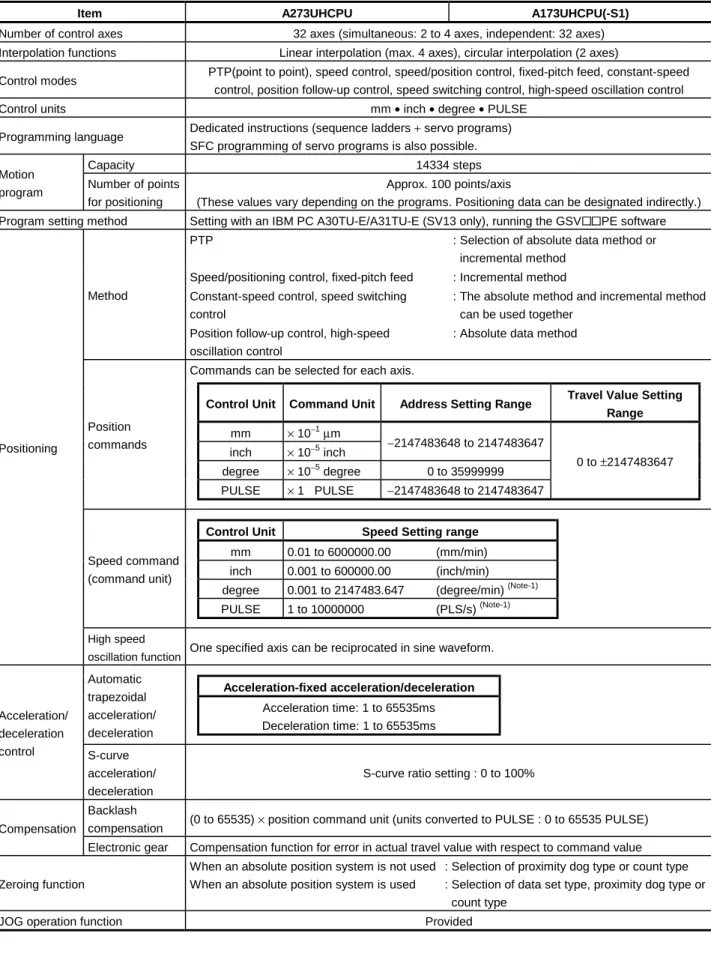
Differences between A273UHCPU, A173UHCPU(-S1) and A172SHCPUN
Item A173UHCPU(-S1) A172SHCPUN A273UHCPU
Number of control axes 32-axes 8-axes 32-axes
SV 13
3.5ms/1 to 20 axes 7.1ms/21 to 32 axes
SV 13
3.5ms/1 to 12 axes 7.1ms/13 to 24 axes 14.2ms/25 to 32 axes Operation cycle
SV 22
3.5ms/1 to 12 axes 7.1ms/13 to 24 axes 14.2ms/25 to 32 axes
3.5ms/1 to 8 axes SV 22
3.5ms/1 to 8 axes 7.1ms/9 to 18 axes 14.2ms/19 to 32 axes A173UHCPU Max. 64 pcs.
Motion control
Cam data A173UHCPU
-S1 Max. 256 pcs. Max. 64 pcs. Max. 256 pcs.
PLC CPU A3UCPU equivalent A2SHCPU (memory
enhanced) equivalent A3UCPU equivalent Direct 0.25 to 1.9
Processing speed (µs/step) 0.15
Refresh 0.25 0.15
Number of real I/O points 2048 points(Range of one
extension base) 1024 points 2048 points
Number of I/O device points 8192 points 2048 points 8192 points
Memory capacity
256k bytes (for A173UHCPU)
1024k bytes (for A173UHCPU-S1)
192k bytes Varies with memory cassette
Main sequence 30k steps 30k steps 30k steps
Program capacity
Sub sequence 30k steps None 30k steps
Internal relay (M) 8192 points 2048 points 8192 points
Link relay (B) 8192 points 1024 points 8192 points
Timer (T) 2048 points 256 points 2048 points
Data register (D) 8192 points 1024 points 8192 points
Link register (W) 8192 points 1024 points 8192 points
Annunciator (F) 2048 points 256 points 2048 points
Number of device points
Index register (V, Z) 14 points 2 points 14 points
Sequence control
Number of PLC extension bases 1 base 1 base 7 bases
Number of SSCNET interfaces 4 channels 2 channels 4 channels
Number of motion slots 8 slots
(A178B-S3 use)
2 slots (A178B-S1 use)
8 slots × up to 4 extension bases allowed Pulse generator/synchronous
encoder, external signal input modules
Four A172SENC modules usable
One A172SENC module usable
Four A287EX/A273EX usable
PBUS I/O module 256 points 256 points 256 points
Manual pulse generator 3 pcs. usable 1 pc. usable 3 pcs. usable
Synchronous encoder (SV22) 4 pcs. usable 1 pc. usable 12 pcs. usable
NMI input 1 point 1 point 3 points
System configuration
High-speed read
PLC input module 8 points 8 points 8 points
Sequence program/parameters Servo program
Mechanical system program (SV22)
Those started on A173UHCPU and created on A273UHCPU (32-axes feature) by file read can be
patibility
1. GENERAL DESCRIPTION
1.1 System Configuration
1.1.1 A273UHCPU System overall configuration
The following system configuration assumes use of the A273UHCPU.
A62P A273UH CPU
A278 LX
A240 DY
A221 AM-20
A211 AM-20
A222AM-20 A230P
A270BATCBL MR-J-BAT
Emergency stop input A6BAT
AC100/200V Brake output Battery module
Regenerative brake resistor Three-phase power supply 200V
DBOUT DBCOM
DB IN+
DB IN-
M E M E
M E
M E M E
External input signals Upper limit switch Lower limit switch Stop signal Proximity dog Speed-position change
PLC extension base connection cable(A370C B)
d1
M E
d2
M E
d3
M E
d8
M E Servo amplifier, max. 8 axes/1 network
Termination resistor Max. 24 axes
MR-H-BN/MR-J2S-B/MR-J2-B (Max. 32 axes including those of ADU)
PLC extension bases: up to 7 bases Base number setting: base 1 to base 7
PLC extension base(A68B/A65B/A62B) (AC B)
Power supply module
PLC slots Max. 16 ADU axes
SSCNET1
SSCNET2 SSCNET3 Teaching unit
A31TU/A30TU(SV13 only)
Windows NT/98
Personal computer(IBM PC/AT)
SSCNET4
SSC I/F card/board (A30CD-PCF/A30BD-PCF)
RS422 CPU base unit (A278B/A275B)
Control power supply module CPU module Servo external signal Dynamic brake module Servo power supply module
Motion slots
AC motor drive modules
BRAKE
A62P AI61 AX AY AH42
A42XY Motion extension base unit
(A268B)
Control power supply module Pulse generator/ synchronous encoder interface module Interrupt input module A273 EX
×8
External interrupt input signals 16 points (I0 to I15) P
Manual pulse generator (MR-HDP01)
E Serial absolute
synchronous encoder (MR-HENC)(SV22 only)
External input signal TRA Tracking
Input module Output module I/O composite module
Motion extension base, up to 4 bases Motion extension base
connection cable (AC B)
×3
×3
Communication cable (A270CDCBL M/
A270BDCBL M)
×3
Serial absolute synchronous encoder cable (MR-HSCBL M)
1. GENERAL DESCRIPTION
1.1.2 A173UHCPU(-S1) System overall configuration
Windows NT/98
d1
M E
d2
M E
d3
M E
d8
M E Servo amplifier, max. 8 axes/1 network
Termination resistor MR-H-BN/MR-J2S-B/MR-J2-B
Servo amplifier, max. 32 axes SSCNET1
A173UHCPU A172S ENC
A1S I61
Emergency stop input
A6BAT
Teaching unit A31TU-E/A30TU-E (SV13 only)
Communication cable (A270CDCBL M/
A270BDCBL M) Personal computer (IBM PC/AT)
SSCNET4
SSC I/F card/board (A30CD-PCF/A30BD-PCF)
RS422
CPU module Interrupt input module
External interrupt input signals 16 points (I0 to I15) P
Manual pulse generator (MR-HDP01)
E
External input signals
FLS Upper limit switch RLS Lower limit switch STOP Stop signal
DOG/CHANGE Proximity dog/speed-position change TRA Tracking
Brake output Motion network cable
Motion slots
Battery
AC100/200V
Power supply module
PLC extension base For A1S6 B: up to 1 base
For A168B (GOT compatible) : up to 1 base For A6 B : up to 1 base
A172S ENC
A172S ENC
A172S ENC Pulse generator/
synchronous encoder interface module
P P
E E E
SSCNET3 SSCNET4
Max. 24 axes
SSCNET2
Extension cable
A1SC B: For A1S6 B, A168B A1S NB: For A6 B CPU base unit
A178B-S3 /A178B-S2 /A178B-S1 /A17 B
GOT
(Note)
(Note): The A173UHCPU may be used with 4 channels of SSCNET.
When using the SSC I/F card/board (A30CD-PCF/A30BD-PCF), connect it to SSCNET4 and connect the servo amplifiers to SSCNET1 to 3.
In this case, up to 24 axes of servo amplifiers can be connected.
×3
×4
×8
×1
(Note)
Serial absolute
synchronous encoder cable (MR-HSCBL M) Serial absolute synchronous encoder (MR-HENC)
POINTS
(1) Use the A168B when using the bus-connection type GOT.
(2) Using the A31TU teaching unit provided with deadman switch requires the exclusively used
A31TUCBL03M connection cable between the CPU module and A31TU connector. The A31TU will not operate at all if it is connected directly with the RS422 connector of the CPU, without using the exclusively used cable.
Also, after disconnecting the A31TU, fit the A31SHORTCON short connector designed for A31TUCBL.
(3) The motion slots also accept PLC A1S I/O modules.
(4) The motion slots accept one A1SI61 interrupt input module.
This module is designed for only event/NMI input to the motion CPU and is irrelevant to PLC interrupt programs.
(5) The motion slots accept up to 256 I/O points.
(6) The I/O numbers of the I/O modules loaded in the motion slots should be later than the I/O numbers
1. GENERAL DESCRIPTION
1.2 Table of Software Package
Programming Software Package
Operating System Software Package
Model Name Applicable version
Use Peripheral Devices
Model Name
For A173UH For A273UH For A173UH
For A273UH
Teaching function
Japanese SW3RNC-GSV From 00F on Without restriction For conveyor
assembly SV13
With Motion SFC
IBM PC/AT NT/
98 English SW3RNC -GSVE Without restriction
Without restriction
SW3RN- SV13B
SW3RN-
SV13X Yes
Japanese SW2SRX-GSV13P From 0AC on
DOS English SW2SRX-GSV13PE From 00J on
Japanese SW3RNC-GSV From 00F on From 00F on For conveyor
assembly SV13
Without Motion SFC
IBM PC/AT NT/
98 English SW3RNC-GSVE Without
restriction
SW2SRX- SV13B
SW0SRX-
SV13V Yes
Japanese SW3RNC-GSV From 00F on Without restriction For automatic
machinery SV22
With Motion SFC
IBM PC/AT NT/
98 English SW3RNC -GSVE Without restriction
Without restriction
SW3RN- SV22A
SW3RN-
SV22W No
SW2SRX-GSV22P From 0AC on
Japanese
SW0SRX-CAMP From 00B on
SW2SRX-GSV22PE From 00J on
DOS English
SW0SRX-CAMPE Without
restriction
Japanese SW3RNC-GSV From 00F on From 00F on For automatic
machinery SV22
Without Motion SFC
IBM PC/AT
NT/
98 English SW3RNC-GSVE Without
restriction
SW2SRX- SV22A
SW0SRX-
SV22C No
(1) Software package versions which accept the setting of the MR-J2S-B servo amplifier
For the following combinations of the programming software packages and operating system software packages, the MR-J2S-B servo amplifier is made usable by setting the servo amplifier to the "MR-J2S series" and the servo motor to "Auto" in the programming software package system settings.
Programming Software Package Operating System Software Package
Model Version A273UHCPU Version A173UHCPU(-S1) Version
SW2SRX-GSV13P AD or later
SW2SRX-GSV13PE J or later SW2SRX-SV13V AF or later SW2SRX-SV13B AF or later
SW2NX-GSV13P AC or later SW2NX-SV13V AF or later SW2NX-SV13B AF or later
SW2SRX-GSV22P AD or later
SW2SRX-GSV22PE J or later SW2SRX-SV22U AF or later SW2SRX-SV22A AF or later
SW2NX-GSV22P AC or later SW2NX-SV22U AF or later SW2NX-SV22A AF or later
SW3RNC-GSV SW2SRX-SV13V SW2SRX-SV13B
SW3RNC-GSVE G or later
SW2SRX-SV22U AF or later
SW2SRX-SV22A AF or later
1. GENERAL DESCRIPTION
1.3 Positioning Control by the Servo System CPU
A servo system CPU can execute positioning control and sequence control for 32 axes by means of a CPU for multi-axis positioning control (hereafter called the
"PCPU") and a CPU for sequence control (hereafter called the "SCPU").
Sequence control capabilities are equivalent to those of A3U.
(1) Control handled by the SCPU (a) Sequence control
The SCPU controls I/O modules and special function modules in accordance with the sequence program.
(The method for executing a sequence program is the same as for an A3UCPU.)
(b) Start of positioning start in accordance with sequence program, and setting of positioning data
1) The Start requests execution of servo programs by means of the SVST instruction (up to 4 axes for interpolation).
2) It changes current values or speed by means of the CHGA/CHGV instruction.
3) It changes the torque limit value by means of the CHGT instruction.
4) It executes JOG operation.
5) It sets the data required to execute manual pulse generator operation.
(2) Control handled by the PCPU
(a) The PCPU executes servo programs whose execution is requested by a SVST instruction issued by the sequence program, and performs the set positioning control.
Positioning control data is defined in the positioning control parameters and the servo program.
(b) It changes the feed current value or positioning speed at the servo side in accordance with the current values or speeds set by CHGA/CHGV instructions issued by the sequence program.
(c) It changes the torque limit value of the designated axis to that defined by the CHGT instruction.
(d) It executes positioning when the manual pulse generator is used.
(e) It executes the teaching designated with the teaching unit (A30TU- E/A31TU-E).
1. GENERAL DESCRIPTION
[Executing Positioning Control with a Servo System CPU]
The servo system CPU executes positioning control in accordance with the servo programs designated by the sequence program of the SCPU.
An overview of the method used for positioning control is presented below.
Servo System CPU System
Request for execution of servo program
"Execute positioning" command Interlock condition for axis 1
Servo program No.15 Axis 1 (Controlled axis No.) Servo program start request M2001
SVST J1 K15
Sequence program Created and modified using a peripheral device(Note-1) SCPU Control
Example: SVST instruction
1) In the sequence program, the servo program number and controlled axis number are set with the SVST instruction.
2) When the SVST instruction is executed, the PCPU is requested to execute the program with the designated servo program number.
(1) Servo programs and positioning control parameters are set using a peripheral device.
(2) Positioning is started by the sequence program (SVST instruction).
(a) The servo program number and controlled axis number are designated by the SVST instruction.
1) The servo program number can be set either directly or indirectly.
2) The controlled axis number can only be set directly.
1. GENERAL DESCRIPTION
(3) The positioning specified by the designated servo program is executed.
<K 15>
ABS-1
Axis 1, 10000
Speed 1000
Dwell time 100
M-code 10
Servo amplifier
Servo motor Servo program Created and modified using a
peripheral device (Note-1)
Positioning control parameters
Set and change using a peripheral device*1 System settings System data such as axis allocations Fixed parameters Fixed data decided, for example, by
the mechanical system
Servo parameters Data decided by the specifications of the connected servo equipment
Parameters block Data required to execute acceleration, deceleration, etc. in positioning control Zeroing data
JOG operation data Data required for JOG operation Limit switch output
data ON/OFF pattern data required to execute the limit switch output function
Servo program No.15
(Program number allowing program designation with the SVST instruction.)
Servo instruction
(Designation of the positioning control method) Positioning data which must be set:
Axis used, positioning address, positioning speed, etc.
Positioning data to be set if required:
Dwell time, M-code, etc.
PCPU Control
Data required to execute zeroing
REMARK
(Note-1): Any of the following peripheral devices, running the SW2SRX- GSV13PE/SW2SRX-GSV22PE software, can be used.
• An IBM PC/AT or 100% compatible machine in which PC-DOS 5.0
1. GENERAL DESCRIPTION
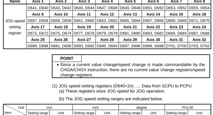
[Executing JOG Operation with a Servo System CPU]
The servo system CPU can be used to perform JOG operation on a designated axis in accordance with a sequence program.
An overview of JOG operation is presented below.
Servo System CPU System
Request for execution of JOG operation
(M3202) M2001
M10
JOG speed setting command Interlock signal for axis 1
JOG speed setting
Setting of "JOG speed setting completed flag"
M3203 Forward JOG exe- cution command
Reverse JOG execution command (for interlock)
Switchs the forward JOG execution command (M3202) ON/OFF
DMOVP K1000 D640
SET M10
Sequence program Created and modified using a peripheral device(Note-1) SCPU Control
In the sequence program, after setting the JOG speed, turn the JOG operation execution flag ON.
(1) Set the positioning control parameters using a peripheral device.
(2) Using the sequence program, set the JOG speed in the JOG operation speed setting register for each axis.
(3) JOG operation is executed while the JOG operation execution flag is kept ON by the sequence program.
1. GENERAL DESCRIPTION
Servo motor Servo amplifier
Positioning control parameters
Set and changed using a peripheral device(Note-1) System settings System data such as axis allocations Fixed parameters Fixed data decided, for example, by
the mechanical system
Servo parameters Data decided by the specifications of the connected servo equipment
Parameter block Data required to execute acceleration, deceleration, etc. in positioning control Zeroing data Data required to execute zeroing JOG operation data Data required to execute JOG operation Limit switch output
data
ON/OFF pattern data required to execute the limit switch output function
PCPU Control
REMARK
(Note-1): Any of the following peripheral devices, running the SW2SRX- GSV13PE/SW2SRX-GSV22PE software, can be used.
• IBM PC
1. GENERAL DESCRIPTION
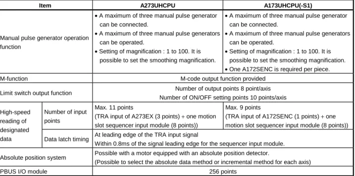
[Executing Manual Pulse Generator Operation with a Servo System CPU]
When executing positioning control with a manual pulse generator connected to an A273EX or A172SENC, manual pulse generator operation must be enabled by the sequence program.
An overview of positioning control using manual pulse generator operation is presented below.
Servo System CPU System
Manual pulse generator used Operated axis number 1 pulse input magnification Manual pulse generator enable
SET M2051
RST M2051 Resetting of axis 1 manual pulse generator operation enable flag
MOVP K1 D714
MOVP K100 D720 Operated axis Input manual pulse generator used
Setting for controlling axis 1 with manual pulse generator P1
1 pulse input magnification setting is 100
Setting of axis 1 manual pulse generator operation enable flag
Manual pulse generator operation completed flag
Sequence program SCPU Control
Use the sequence program to turn the manual pulse generator operation enable flag ON after setting the manual pulse generator used, operation number, and magnification for 1 pulse input.
(1) Set the manual pulse generator used, operated axis number, and magnification for 1 pulse input by using the sequence program.
(2) Turn the manual pulse generator operation enable flag ON by using the sequence program.
... Manual pulse generator operation enabled (3) Perform positioning by operating the manual pulse generator.
(4) Turn the manual pulse generator operation enable flag OFF by using the sequence program.
... Manual pulse generator operation completed
1. GENERAL DESCRIPTION
Servo amplifier
Servo motor PCPU
Manual pulse generator
1. GENERAL DESCRIPTION
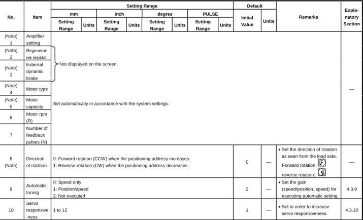
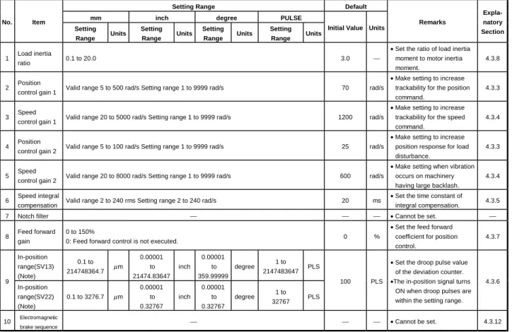
(1) Positioning control parameters
The positioning control parameters are classified into the seven types shown below.
Parameter data can be set and corrected interactively by using a peripheral device.
Item Description Reference
1 System settings The system settings set the modules used, axis numbers, etc. Section 4.1
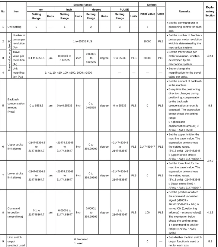
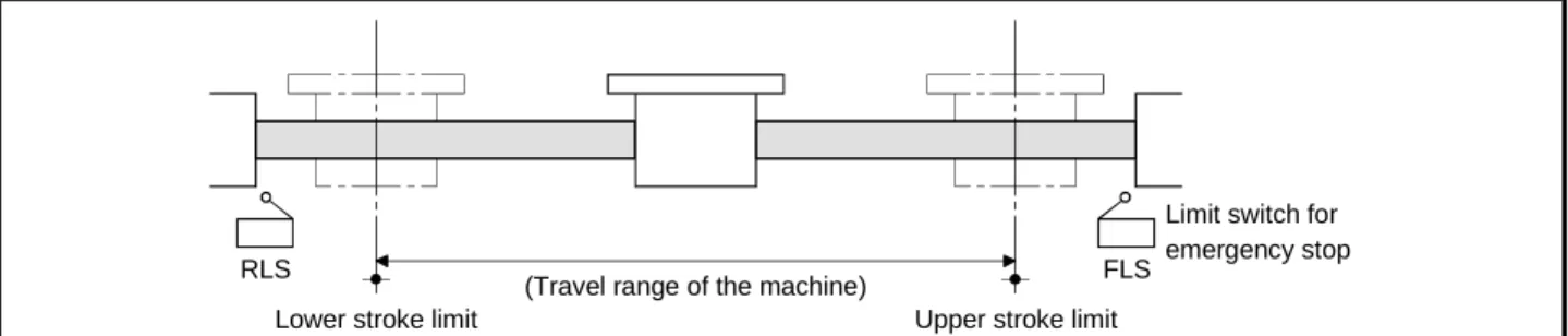
2 Fixed parameters
Fixed parameters are set for each axis. Their settings are predetermined by the mechanical system. They are used for servo motor control during positioning control.
Section 4.2
3 Servo parameters
Servo parameters are set for each axis. Their settings are predetermined by the type of servomotor connected. They are set to control the servomotors during positioning control.
Section 4.3
4 Zeroing data Zeroing data is set for each axis. The return direction, return
method, return speed, etc. are set for zeroing. Section 7.21 5 JOG operation JOG operation data is set for each axis. The speed limit value
and parameter block number are set for JOG operation. Section 7.19
6 Parameter block
Up to 16 parameter blocks are set for acceleration, deceleration, speed control, etc. during positioning control.
They are designated by the servo program, JOG operation data, and zeroing data to easily change acceleration and deceleration (acceleration time, deceleration time, and speed limit value) during positioning control.
Section 4.4
7 Limit switch output data
Limit switch output data (ON/OFF pattern data) is set for each axis to be used when "USE" is set for the limit switch output setting in the fixed parameter. When positioning control takes place on an axis for which limit switch output data has been set, the set ON/OFF pattern of the axis is output to an external destination.
Section 8.1
(2) Servo program
A servo program is a program for executing positioning control and is run in response to a start request from the sequence program.
It comprises a program number, servo instructions, and positioning data.
For details, see Chapter 6.
• Program No. ... This number is designated in the sequence program.
• Servo instruction ... This instruction indicates the type of positioning control to be executed.
• Positioning data ... This data is required to execute servo instructions.
The data required is fixed for each servo instruction.
(3) Sequence program
The sequence program serves to enable the execution of positioning control by servo programs, JOG operation, and manual pulse generator operation.
For details, see Chapter 5.
2. PERFORMANCE SPECIFICATIONS
2. PERFORMANCE SPECIFICATIONS
2.1 SCPU Performance Specifications
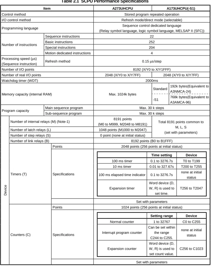
Table 2.1 gives the performance specifications of the SCPU.
Table 2.1 SCPU Performance Specifications
Item A273UHCPU A173UHCPU(-S1)
Control method Stored program repeated operation
I/O control method Refresh mode/direct mode (selectable)
Programming language Sequence control dedicated language
(Relay symbol language, logic symbol language, MELSAP II (SFC))
Sequence instructions 22
Basic instructions 252
Special instructions 204
Number of instructions
Motion dedicated instructions 4
Processing speed (µs)
(Sequence instruction) Refresh method 0.15 µs/step
Number of I/O points 8192 (X/Y0 to X/Y1FFF)
Number of real I/O points 2048 (X/Y0 to X/Y7FF) 2048 (X/Y0 to X/Y7FF)
Watchdog timer (WDT) 2000ms
Standard 192k bytes(Equivalent to A3NMCA-24)
Memory capacity (internal RAM) Max. 1024k bytes
-S1 768k bytes(Equivalent to A3AMCA-96)
Main sequence program Max. 30 k steps
Program capacity
Sub-sequence program Max. 30 k steps
Number of internal relays (M) (Note-1) 8191 points
(M0 to M999, M2048 to M8191) Number of latch relays (L) 1048 points (M1000 to M2047) Number of step relays (S) 0 point (none at initial status)
Total 8191 points common to M, L, S
(set with parameters)
Number of link relays (B) 8192 points (B0 to B1FFF)
Points 2048 points (256 points at initial status)
Time setting Device 100 ms timer 0.1 to 3276.7s T0 to T199
10 ms timer 0.01 to 327.67s T200 to T255 100 ms elapsed time indicator 0.1 to 3276.7s none at initial
status
Expansion timer
Word device (D, W, R) is used to
set time.
T256 to T2047 Specifications
Timers (T)
Set with parameters
Points 1024 points (256 points at initial status)
Setting range Device Normal counter 1 to 32767 C0 to C255
Interrupt program counter
Can be set within the range C244 to C255.
none at initial status Word device (D,
Specifications
Device
Counters (C)
2. PERFORMANCE SPECIFICATIONS
Table 2.1 SCPU Performance Specifications (Continued)
Item A273UHCPU A173UHCPU(-S1)
Number of data registers (D) (Note-1) 8192 points (D0 to D8191)
Number of link registers (W) 8192 points (W0 to W1FFF)
Number of annunciators (F) 2048 points (F0 to F2047)
Number of file registers (R) Max. 8192 points (R0 to R8191) (set with parameters)
Number of accumulators (A) 2 points (A0, A1)
Number of index registers (V, Z) 14 points (V, V1 to V6, Z, Z1 to Z6)
Number of pointers (P) 256 points (P0 to P255)
Number of interrupt pointers (I) 32 points (I0 to I31)
Device
Number of special-function relays (M) 256 points (M9000 to M9255)
Number of special-function registers (D) 256 points (D9000 to D9255)
Standard Max. 10 blocks Number of expansion file register block (Note-2) Max. 46 blocks
(set by memory capacity) -S1 Max. 46 blocks
Number of comments Max. 4032 (64k bytes), 1 point = 16 bytes
(Set in 64-point unit)
Number of expansion comments (Note-3) Max. 3968 points (63k bytes), 1 point = 16 bytes (Set in 64-point unit)
Self-diagnostic function
Watchdog error monitoring, memory/CPU/input/output/battery, etc error detection
Watchdog error monitoring (Watchdog timer fixed to 200ms)
Operation mode on error Select stop/continue
Output mode selection when switching from STOP to RUN
Select re-output operation status before STOP (default) or output after operation execution.
Clock function (Note-4) Year, month, day, hour, minute, day of the week (leap year automatic distinction)
Program/parameter storage in ROM Max. 64 kbytes Not possible
RUN-time start method Initial start
Latch (power failure compensation) range L1000 to L2047 (default) (Latch range can be set for L, B, T, C, D, W) Remote run/pause contact Using X0 to X1FFF, one point can be set for each of the RUN and
PAUSE contacts.
I/O assignment Number of occupied I/O points and module type can be registered.
Step run Sequence program operation can be executed and stopped.
Interrupt processing Using interrupt or fixed-cycle interrupt signal, interrupt program can be executed.
Data link MELSECNET/10, MELSECNET
(Note-1): Range of positioning dedicated devices differs depending on the OS. For details, see Chapter 3.
(Note-2): No. of extension fide register blocks varies depending on the setting of program capacity, No. of file registers, or No. of comments.
(Note-3): The expansion comments are not stored in the internal memory of the CPU.
(Note-4): The year data by the clock element is only the lower two digits of the year.
When used in sequence control, the data must be compensated for the sequence program in some applications of using the data.