A Flow Control Scheme Based on Per Hop and Per Flow in Commodity Switches for Lossless Networks
SHIE-YUAN WANG , (Senior Member, IEEE), YO-RU CHEN , HSIEN-CHUEH HSIEH, RUEI-SYUN LAI, AND YI-BING LIN , (Fellow, IEEE)
Department of Computer Science, National Yang Ming Chiao Tung University, Hsinchu 30010, Taiwan Corresponding author: Shie-Yuan Wang (shieyuan@cs.nctu.edu.tw)
This work was supported in part by the Center for Open Intelligent Connectivity from the Featured Areas Research Center Program within the Framework of the Higher Education Sprout Project by the Ministry of Education (MOE) in Taiwan, in part by Barefoot/Intel, in part by Accton, and in part by National Cheng Kung University.
ABSTRACT Performing flow control inside a network can effectively avoid packet loss due to buffer overflow in switches. IEEE 802.3x exercises a per-hop link-based flow control scheme to achieve this goal.
IEEE 802.1Qbb Priority-based Flow Control (PFC) improves IEEE 802.3x by proposing a per-hop per- service-class flow control scheme. Although PFC is better than IEEE 802.3x, it still suffers from several serious problems such as congestion spreading, deadlock, and packet loss. In this work, we propose a per- hop per-flow scheme to mitigate these problems. We design, implement, and evaluate the performance of our scheme in P4 hardware switches. Experimental results show that (1) our scheme outperforms PFC in many aspects including avoiding congestion spreading, deadlock, and packet loss, and (2) the bandwidth overhead of our scheme is only slightly higher than that of PFC.
INDEX TERMS Flow control, IEEE 802.3x, IEEE 802.1Qbb, PFC, P4.
I. INTRODUCTION
Packet losses due to buffer overflow in network switches may occur due to network congestion. If the UDP protocol is used at the transport layer, a UDP sending host will not automatically retransmit lost packets, which may result in poor Quality-of-Service (QoS) of the network applications on the receiving host. Although a TCP sending host will automatically retransmit lost packets, the packet loss detec- tion time of TCP is longer than the round-trip time (RTT) of the TCP connection. For delay-sensitive network applications such as a network file server and its clients or a remote desktop server and its clients, the delays will severely harm their performances.
To prevent dropped packets due to buffer overflow in network switches, IEEE 802.3x [1] proposed a per-hop link-based flow control scheme to ensure zero packet loss between two adjacent network nodes. Because IEEE 802.3x is link-based, when a link is stopped, all flows on the link are stopped, including those flows that are not congested
The associate editor coordinating the review of this manuscript and approving it for publication was Yang Tang .
in the downstream node. Besides, when a link is stopped due to a high buffer usage of low-priority flows, flows of high priorities are stopped as well. Such problems can easily lead to a low link utilization and unfairness among flows.
To solve these problems, the IEEE 802.1Qbb priority- based flow control (PFC) scheme [2] was proposed. To sup- port QoS, the IEEE 802.1p task group defines a 3-bit Priority Code Point (PCP) field to define 8 priority levels, where 7 represents the highest priority and 0 represents the lowest priority. The default value is 0. Each priority level defines a unique class of service (CoS). To comply with IEEE 802.1p, PFC supports eight different priorities and in PFC an input port can have up to eight different CoS ingress queues. PFC has been widely adopted for a variety of lossless networks such as Fiber Channel over Ethernet (FCoE) and RDMA over Converged Ethernet version 2 (RoCEv2) [3], which is used by some data center networks [4].
Although PFC enhances IEEE 802.3x, it still suffers from problems such as unfairness and head-of-line block- ing [4]. Furthermore, PFC can cause congestion spread- ing problem [4]–[6] and result in a significant performance
degradation. Even worse, PFC can lead to deadlock [6]–[10]
that causes an entire network to enter a standstill situation.
Enhancing PFC with a per-hop per-flow flow control mechanism can potentially solve many PFC problems. For example, the pause/resume flow control can be applied to an individual flow rather than to all flows belonging to the same service class. As a result, there is no victim flow in the network and the unfairness problem among flows no longer exists. Besides, because each flow is individually allo- cated a separate buffer space in the switch, the deadlock and congestion spreading scenarios and their resulting low link utilization problems no longer exist. For this reason, BFC [11]
proposed a clean-slate per-hop per-flow flow control design and showed its superior performance under different situa- tions via simulations.
In an ideal situation, each flow should have its own buffer usage state and can be paused and resumed using dedicated egress queue independently in a per-hop per-flow flow con- trol scheme. Currently, to implement IEEE 802.1p, most hardware switches support at least eight priority queues in an output port. However, most of them lack the capability of per-flow queuing in an output port due to its high complexity and cost. To resolve this issue, this paper proposes a novel flow control scheme called PFFC based on per hop and per flow.
In PFFC, we design a per-flow based buffer usage account- ing mechanism to decide which flow should be paused or resumed according to per-flow thresholds. This mechanism uses the concepts of default egress queue (DEQ) and paused egress queue (PEQ). If a flow needs to be paused, PFFC immediately directs its packets to a PEQ. When the flow can be resumed, PFFC immediately directs its packets back to the DEQ. PFFC reuses PFC’s PAUSE and RESUME control frames to pause and resume an egress queue. When the number of flows passing an output port is too large, PFFC maps multiple flows to an egress queue. In addition to using per-flow buffer usage thresholds, PFFC also uses system buffer usage thresholds to protect the usage of buffers.
We successfully implement PFFC in programmable hard- ware switches [12], [13] using the P4 language [14]. These switches use Intel/Barefoot’s Tofino chip as their switching ASIC [15] and their data planes are programmable. We eval- uate the real-world performance of PFFC on a multi-hop network testbed composed of several P4 switches and hosts.
Experimental results show that PFFC outperforms PFC in many aspects and its bandwidth overhead is only slightly higher than that of PFC. In summary, our contributions are listed as follows.
• We design a novel per-hop per-flow flow control scheme named PFFC and successfully implement it in P4 hard- ware switches.
• We identify the conditions in which packets may be dropped in PFC.
• We evaluate the real-world performance of PFFC in different aspects including multi-hop, multi-flow, multi-
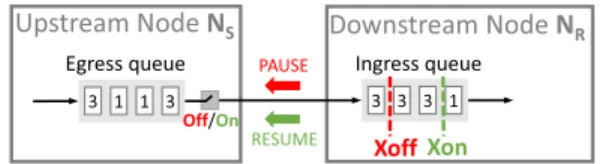
FIGURE 1. The concept of IEEE 802.3x.
protocol-type (TCP vs. UDP), and multi-flow-type (mice flows vs. elephant flows) scenarios and show that PFFC maintains high-performance and low-overhead over multi-hop networks.
• We show that PFFC does not have the circular wait deadlock. Experimental results show that congestion spreading and packet loss problems are mitigated, and the average flow completion time of mice flows in PFFC is shorter than that in PFC.
This paper is organized as follows. SectionII gives the background, compares our work with related work, briefly presents the P4 switch architecture to help readers under- stand the design and implementation of PFFC. SectionIII presents the detailed design and implementation of PFFC.
In SectionIV, we evaluate and compare the performances of PFFC with those of PFC. We discuss our future work in SectionV. Lastly, we conclude the paper in SectionVI.
II. BACKGROUND AND RELATED WORK
The concept of IEEE 802.3x is illustrated in Fig.1, in which a small box represents a packet and the number on it represents the flow ID of the packet. The ingress queue is the queue used in an input port of the downstream node NRwhile the egress queue is a queue used in an output port of the upstream node NS. When the buffer usage of the ingress queue of NR exceeds a specific threshold Xoff, NR will promptly send a PAUSE frame to NSto ask it to stop sending packets. Later on, when the buffer usage drops below another threshold Xon, NR will send a RESUME frame to NSto resume transmission of packets on the link. To ensure that no packets are dropped in a network due to buffer overflow in any switch, IEEE 802.3x is exercised on every link. As mentioned in SectionI, IEEE 802.3x suffers from several problems. This section describes the existing solutions for these problems.
A. PRIORITY-BASED FLOW CONTROL (PFC)
PFC, like IEEE 802.3x, is a per-hop flow control scheme and needs to be exercised on the links where reliable Ethernet is required. Furthermore, it supports priority differentiation when performing flow control. When packets enter a switch via an input port, they are placed in different ingress queues of the input port based on their priorities, and the pause/resume flow control scheme is independently applied to these ingress queues.
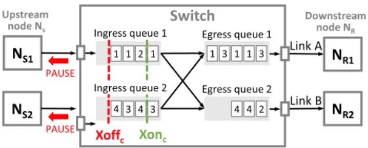
Fig.2shows the design of PFC for a shared-buffer switch in a logical view. PFC uses the ingress perspective and the egress perspective at the same time to limit the maximum buffer usage of a specific CoS in a switch [16], [17]. As explained
FIGURE 2. The PFC design in a switch.
previously, each input port has eight CoS ingress queues and each output port has eight CoS egress queues. When a packet enters a switch, it is stored in a packet buffer shared by all ports of the switch. This shared packet buffer does not belong to any input port or output port. Based on the CoS of a packet, the packet is logically linked into the CoS queue of the input port where it comes from and at the same time linked into the CoS queue of the output port where it should be forwarded out of the switch. To illustrate this relationship, in Fig.2, if there are n packets of a specific flow in the ingress queues, there are exactly n packets of that flow in the egress queues.
Each CoS ingress queue in an input port is configured a maximum queue length and its Xoffc and Xonc thresholds are properly set based on its maximum queue length setting.
As explained previously, based on the current buffer usage of a CoS ingress queue, the switch will send PAUSE or RESUME frames to the upstream node to prevent packet dropping in its CoS ingress queue. Each CoS egress queue in an output port also has a maximum queue length setting.
When its current buffer usage exceeds the specified maxi- mum queue length setting, the packet to be linked into it will be dropped.
In PFC, the PAUSE frame contains a timeout value. After the timer expires, the transmission at the upstream node automatically resumes. Setting the Xoffc value should con- sider the bandwidth-delay product (BDP) of the link between the switch and the upstream node. After the switch sends a PAUSE frame to the upstream node, the packets from the upstream node will keep filling up the CoS ingress queue of the switch during the RTT between the switch and the upstream node. Therefore, the Xoffc value should be set to a value such that the space between Xoffcand the size of the CoS ingress queue is larger than the BDP to accommodate these in-flight packets. This space is called the headroom of the queue [16], [17]. A RESUME frame is used to shorten the timeout duration at the upstream node. Because when the switch sends a RESUME frame, it takes the RTT for packets from the upstream node to arrive, to achieve high switch utilizations, setting the Xonc value should also consider the BDP of the link between the switch and the upstream node and it should not be too small.
Numerous approaches have been proposed for solving the problems with PFC, which can be classified into four cate- gories: (i) to focus on solving PFC deadlock problem [9],
[10], (ii) to enhance PFC with other methods such as con- gestion control [7], [18] or telemetry technique [7], [18], [19], (iii) to avoid using PFC [20], [21], and (iv) to revisit finer-grained flow control schemes [11].
Although these methods can work around some prob- lems with PFC, none of them can completely solve all of these problems using off-the-shelf hardware. For example, both Tagger [9] and GFC [10] can solve deadlock prob- lems but cannot solve congestion spreading issues. The con- gestion control methods such as DCTCP [22], QCN [23], DCQCN [7], TIMELY [24], HPCC [18], and Swift [25] rely on using an end-to-end control loop, which causes larger tail latency than the tail latency caused by hop-by-hop based approaches. Besides, these methods cannot solve PFC dead- lock and congestion spreading problems.
B. CONGESTION SPREADING IN PFC
Fig.2 shows an example of congestion spreading in PFC.
Each small box in the queues represents a packet and the number on the box indicates its flow ID. Flow 1 comes from NS1 and Flow 3 comes from NS2and they are destined to NR1; Flow 2 comes from NS1and Flow 4 comes from NS2 and they are destined to NR2. All of these flows use the default CoS and thus the packets of Flow 1 and Flow 2 share Ingress queue 1 while the packets of Flow 3 and Flow 4 share Ingress queue 2. The link bandwidth between the switch, senders (NS1, NS2), and receivers (NR1, NR2) are the same.
Consider the following condition: Flows 1 and 3 are send- ing at the line rate but Flows 2 and 4 are sending at a half of the line rate. This means that the total sending rate of Flows 1 and 3 exceeds the bandwidth of Link A. As a result, Egress queue 1 quickly builds up. Suppose that the size of Egress queue 1 is larger than the sum of the sizes of Ingress queue 1 and Ingress queue 2, which are used by the two flows, respectively. In such a setting, before Egress queue 1 overflows, the buffer usages of Ingress queue 1 and Ingress queue 2 will have exceeded the Xoffc value configured for them. (Note that the Xoffc configured for an Ingress queue must be less than the size of the Ingress queue.) This means that PFC at the two input ports has already been triggered to send PAUSE frames to NS1and NS2. Thus, the packets of Flows 1 and 3 will not be dropped in Egress queue 1.
When the PAUSE frames are received by NS1 and NS2, because in this case all flows use the same CoS, NS1 and NS2will immediately pause all of their flows destined to the switch. Thus, although the congestion is caused by Flows 1 and 3, Flows 2 and 4 are also paused. Because the packets of Flows 2 and 4 are blocked from transmitting at NS1and NS2, they quickly build up and cause congestion at NS1and NS2. Such congestion will be spread to all upstream nodes of Flows 2 and 4 even though their packets are destined to NR2, where no congestion exists. In this case, Flows 2 and 4 are victim flows and their packets sometimes cannot be forwarded by the switch. Ideally, the utilization of Link B should be 100%. However, when PFC is enabled, because
Flows 2 and 4 are unnecessarily paused, the utilization of Link B will be unnecessarily reduced.
Because the number of flows on a link generally is much larger than eight, which is the number of CoS ingress queues in an input port, inevitably multiple flows will share the same CoS ingress queue in an input port. Thus, some flows sharing the same CoS ingress queue may become victim flows due to congestion spreading. The congestion spreading problem can be avoided in PFFC. The details will be given in SectionIV-F.
C. DEADLOCK IN PFC
Tagger [9], GFC [10] and PCN [19] study the deadlock formation problem in PFC-enabled lossless networks. PFC deadlock is mainly caused by the Cyclic Buffer Depen- dency (CBD) problem [8], [9]. When PFC is enabled in a loop topology, the occupied buffers are waiting for each other, and packet transmission will be halted immediately after one of the switches get congested. PFC deadlock also occurs in a Clos network topology [4] as transient loops form in data center networks. The deadlock is persistent even after stopping packet transmission from all senders. The deadlock can only be removed until all switches get rebooted.
A deadlock situation on a resource arises if and only if all of the following conditions are met in a system: (1) no preemption, (2) mutual exclusion, (3) hold and wait, and (4) circular wait. In PFFC, every flow is allocated its own buffer space in default egress queue, and no circular waiting condition exists. Therefore, condition (2) does not hold and the deadlock situation will not occur in PFFC. More details will be given in SectionIV-G.
D. PACKET LOSS IN PFC
Although PFC was proposed to prevent packet loss in a switch, we observed a situation in which packets can still be dropped due to the overflow of an egress queue. Consider Flows 1 and 3 in Fig.2. Suppose that the sizes of all ingress queues and egress queues are the same. It may happen that although none of Ingress queues 1 and 2 exceeds the Xoffc threshold, the buffer usage of Egress queue 1 has exceeded its size, causing some packets of Flows 1 and 3 to be dropped.
For example, if Xoffcis set to 3/4 of the ingress queue size, before the buffer usages of Ingress queues 1 and 2 reach Xoffc, the sum of their buffer usages may already exceed the size of Egress queue 1. That is, 3/4 + 3/4 = 6/4 > 1. In this situation, because neither Ingress queue 1 nor Ingress queue 2 exceeds the Xoffcthreshold, PFC will not send any PAUSE frame to NS1or NS2 to stop their packet transmis- sion. If such a traffic pattern persists, this packet dropping phenomenon will continue. Therefore, PFC is vulnerable to TCP incast [26]–[28], especially when the number of ingress queues is large.
One way to resolve this issue is to allocate each egress queue a buffer space that is N times the buffer size of an ingress queue, where N is the number of ports of the switch, which generally is 24, 48, or 64 for a commodity switch. This number is called the buffer oversubscription ratio used for an
egress queue. However, since a switch may encounter traffic patterns in which the packets are spread among all ports, the buffer space of a switch should be shared fairly among all ports and between ingress queues and egress queues. To better utilize the buffer space allocated to an egress queue, some commodity switches can allow an egress queue to have a buffer oversubscription ratio of up to 3:1 [16], [17]. However, it is unrealistic to use the number of ports of a switch as the buffer oversubscription ratio for each egress queue. There- fore, the packet loss problem in PFC cannot be completely avoided.
In PFFC, a flow is allocated its own buffer space so that its buffer usage is individually accounted and controlled. PFFC only uses the egress perspective to limit the buffer usage of a flow. As a result, PFFC does not have the packet loss problem with PFC. The details will be given in SectionIV-D.
E. COMPARISON WITH RELATED WORK
Per-hop flow control can generally be classified into the credit-based flow control and Ethernet flow control. Credit- based flow control [29], [30] have been proposed for ATM networks decades ago and InfinitiBand also uses it [31].
In credit-based flow control, each receiver sends credits to the sender to indicate the availability of receive buffers. The sender needs to obtain credits before transmitting packets to the receiver. The packets of each flow are buffered in sepa- rated queues in the upstream node and can only be transmitted after the downstream node has granted permission.
Because ATM networks are not widely used, credit-based flow control is rarely used in today’s networks. Since PFC is the primary flow control scheme proposed for Ethernet networks, nowadays PFC is used to implement a lossless Eth- ernet network. Recently, because the emergence of RDMA over Converged Ethernet version 2 (RoCEv2) [3] and the deployment of RDMA NICs in data center networks made PFC gain wider traction [4], a variety of approaches have been proposed to either enhance, disable, or solve problems caused by PFC, and they have been discussed SectionII.
Our work differs from prior works as follows. First, we have successfully designed and implemented a per- hop per-flow flow control scheme (PFFC) in P4 hardware switches. In contrast, most of prior works did not use per- hop per-flow flow control. Among these prior works, Back pressure Flow Control (BFC) [11] has independently pro- posed similar ideas to our work. That is, when the number of flows is larger than the number of queues in an output port, some flows need to share the same queue. Except for this unavoidable measure, however, there are many design differences between PFFC and BFC. For example, PFFC uses migrate and migrate-back mechanisms to pause and resume a flow, respectively. On the other hand, the BFC scheme does not have such mechanisms. Instead, it pauses the queue that a congested flow shares with other flows.
As a result, these other flows may be unnecessarily paused as well. The updated BFC work [32] briefly described its imple- mentation on Tofino2 P4 switches without details. The BFC
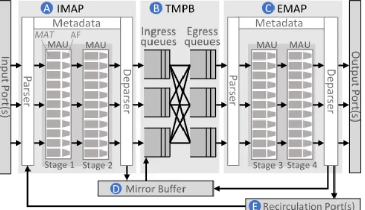
FIGURE 3. The architecture of a P4 hardware switch.
authors claimed that, flows exceeding the number of egress queues will be rare in practice and even that happens a BFC switch can leverage the larger number of queues available at the upstream switches to limit congestion spreading. In this paper, PFFC is proposed as a fresh take and an interesting idea implemented in a capability-limited Tofino1, which also works for Tofino2. In our opinion, both BFC and PFFC are novel implementations for Tofino. We have also tested the behavior of our PFFC scheme and measured its performance in P4 hardware switches under many different settings such as multi-hop, multi-flow, multi-protocol (i.e., TCP vs. UDP), multi-flow-type (i.e., elephant flow vs. mice flow [33]), etc.
These real-world performances are more convincing than simulation results.
F. P4 SWITCH ARCHITECTURE
The programmability of the data plane of a switch is the key enabler to develop a clean-slate PFFC scheme. P4 is one of the emerging programmable data plane technolo- gies that allow developers to design and implement their packet processing logics in the data plane [34]. Based on the P414 language specification, Fig. 3 shows the architecture of a P4 hardware switch [14]. Each packet received by an input port is processed by the following components in a sequential order: Ingress Match-Action Pipeline (IMAP) (Fig. 3 (A)), Traffic Manager & Packet Buffer (TMPB) (Fig. 3 (B)), Egress Match-Action Pipeline (EMAP) (Fig. 3 (C)), and an output port. The two Match-Action pipelines are main programmable components for packet processing. TMPB serves to provide packet queuing (ingress queues and egress queues) and scheduling functions.
In a P4 switch, an important data structure is used to describe the current state of a packet or to specify the opera- tion that the switch should apply to the packet. This structure is called intrinsic metadata and each packet is associated with a metadata instance in the switch. (We use the ‘‘metadata’’
to refer to the ‘‘intrinsic metadata.’’) For example, when a packet passes IMAP, the values of the output port ID and egress queue ID fields of its metadata instance will be deter- mined and set. When the packet leaves IMAP, TMPB will
store it in the specified egress queue of the specified output port based on the information stored in its metadata instance.
In PFFC, a flow may need to be directed to a different egress queue over time and this is achieved by using the above mechanism.
A P4 program is mainly executed in IMAP and EMAP.
Both IMAP and EMAP are comprised of a Parser, several Match-Action Units (MAUs), and a Deparser. The Parser is used to analyze each packet, extract packet header fields, and pass them to a sequence of MAUs. The MAU is the core com- ponent to define the packet processing conditions and action functions. Each MAU is described by a set of Match-Action Tables (MAT), which are defined by a set of Match Keys (packet header fields and metadata used for matching) and Action Functions (AF) (some operations to be applied to the packet). There are multiple MAU stages in a Match- Action Pipeline. Each Match-Action Table can be assigned to a specific stage. Each stage has hardware resources such as memory and ALUs (Arithmetic Logic Units).
The MAUs work in a packet-driven manner. No action function can be invoked without a packet entering the P4 switch. The life scope of the metadata of a packet is the same as that packet. The information that needs to be stored in the P4 switch in a persistent manner should be stored in a memory called register arrays. Every register can be read or written by the ALUs of a MAU. Each register can only be accessed in a specific MAU stage to prevent race condition problems caused by concurrent accesses from multiple stages.
A program written in the P4 language is only a half part of the complete packet processing logic. The set of runtime Match-Action rules is the other half, which is used to describe the association of Match Keys and corresponding Action Functions. When a packet is processed by an MAU, it may be matched by multiple rule entries and the action function(s) of the highest-priority entry will be applied to the packet.
After a packet is processed by IMAP, it is passed to TMPB.
TMPB is composed of shared Packet Buffer and the packet queuing and scheduling modules. The egress port set for a packet in IMAP can be an output port or a recirculation port (Fig.3 (E)). The recirculation port is a special mechanism that enables the packet to be processed again by re-entering IMAP. When a packet is mirrored in IMAP or EMAP, the packet mirroring is implemented using an operation, called
‘‘cloning.’’ The cloned copy will be stored in Mirror Buffer (Fig.3(D)) and later on it will be processed by TMPB.
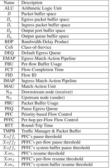
G. ACRONYMS AND SYMBOLS USED IN THIS PAPER The acronyms and symbols used in this paper are summarized in Table1.
III. DESIGN AND IMPLEMENTATION
We have designed and implemented PFFC in Inventec D10056 [13] P4 switches, which use Barefoot’s Tofino chip as their switching ASIC [15]. In the rest of the paper, we use the ‘‘P4 switches’’ to refer to these hardware switches.
The work flow of PFFC is shown in Fig. 4. Our design
TABLE 1. The acronyms and symbols.
includes three main mechanisms: A per-flow based buffer usage accounting mechanism to decide which flow should be paused or resumed according to the per-flow threshold Xofff (where f represents a specific flow) and Xonf values (Fig. 4 (A)), the capability to generate and send per-flow control frames to notify upstream nodes which flows should be paused or resumed (Fig. 4 (B)), and the ability to react to the received per-flow control frames (Fig. 4 (C)). Our PFFC implementation uses PFC’s PAUSE and RESUME control frames to pause and resume an egress queue. We also create custom PFFC control frames named MIGRATE and MIGRATE-BACK to migrate a flow among egress queues.
A packet enters the ingress pipeline following the workflow in Fig.4. Each packet will be parsed and processed. A normal packet will be forwarded to a downstream node. An account- ing packet will be recirculated to the ingress pipeline to decre- ment the counters of the packet. A PFC/PFFC control frame will be mirrored to an upstream node to pause or migrate a flow according to the thresholds.
A. PER-FLOW PAUSE AND RESUME OPERATIONS
If the number of flows passing an output port is less than the number of egress queues in the output port, our P4 code in
FIGURE 4. The high-level workflow of PFFC.
FIGURE 5. The DEQ and PEQs in an output port in PFFC.
IMAP (Fig.3(A)) can direct the packets of these flows to dif- ferent egress queues and independently pause or resume these queues when receiving a PAUSE or RESUME frame from a downstream node. However, due to the high cost and com- plexity to support many per-flow queues in an output port, the number of egress queues per output port in most commodity switches is limited to only eight for supporting the QoS pri- orities defined in IEEE 802.1p. Modern switches can provide more than eight egress queues per output port. Without loss of generality, we assume that there are eight egress queues in an output port. Having more egress queues per output port can mitigate the issues discussed in SectionIII-D.
To support per-flow pause and resume operations under this constraint, when the number of flows passing an output port is large, PFFC maps multiple flows to an egress queue.
In our design, if a flow is not paused, we direct its packets to the default egress queue (DEQ, Fig.5 (B)) of its output port for forwarding. On the other hand, if a flow needs to be paused, we direct its packets to an egress queue that has been paused by our design. In an output port, one egress queue is used as DEQ while the other egress queues are used as the pause egress queue(PEQ, Fig. 5 (C)). Later on, when the paused flow is resumed, we resume the PEQ that is being used by this flow to drain the packets blocked in the PEQ and then redirect the newly incoming packets of the flow
back to the DEQ for forwarding. Since an output port of a commodity switch has eight egress queues in an output port (Fig.5(A)), one egress queue is used as the DEQ and the other seven egress queues are used as PEQs shared by all flows.
PFFC identifies a flow by its flow ID (FID), which is the CRC-32 hash value of the 5-tuple information (including source IP address, source port number, destination IP address, destination port number, and the value of the protocol type) in the packet header. The FID is mapped by a function to a value between 1 and 7 to index one of the seven PEQs. When a switch needs to pause a specific flow, it first uses the FID of the flow to pause the indexed PEQ and then directs newly arriving packets of the flow from the DEQ to the indexed PEQ. This design soon stops the packets of the flow from being transmitted out of the output port. In PFFC, the process of changing a flow’s egress queue between the DEQ and its indexed PEQ is called flow migration.
On the other hand, when an upstream node resumes a specific flow, it first resumes the PEQ indexed by the FID of the flow, which enables the packets blocked in the PEQ to be forwarded out immediately. Besides, the egress queue for this flow in the upstream node is migrated back to the DEQ so that its newly arriving packets will be forwarded using the default queue. This flow migration need not be performed immediately as the paused queue has been resumed and newly arriving packets can still be forwarded through the newly resumed queue. However, since a PEQ may be shared by multiple flows and it may be paused again due to the need to pause a different flow that shares this PEQ, this flow migration still needs to be performed soon so that the packets of the resumed flow will not be unnecessarily blocked again.
Another issue with this many-to-one mapping design is that a flow blocked in a PEQ may be unexpectedly resumed. This phenomenon can happen when another flow shares the same PEQ and the switch needs to resume it. In such a case, the packets of the flow that should be paused in the PEQ may be drained to the downstream node. However, these drained packets will be safely queued in the downstream node and will not be dropped due to buffer overflow in the downstream node.
This no-loss property is achieved because, in addition to pausing and resuming a flow, PFFC also pauses and resumes the upstream nodes of a switch based on the system buffer usage of the switch. As shown in Fig. 5, Xoffs is used to prevent the Packet Buffer (i.e., the system buffer) from over- flowing, where s represents the system. Because there is a headroom reserved for Xoffs, even though a tiny number of packets of a paused flow may ‘‘leak’’ to the downstream node due to unexpected resumption and soon be re-paused, they will not be dropped due to buffer overflow in the downstream node.
When a flow is migrated back to the DEQ, to minimize the chance of packet reordering that may occur during this transition period, we set the highest strict priority (i.e., 7) for PEQs and the lowest (i.e., 0) for DEQ. Thus, for a resumed
flow, all of its packets blocked in its indexed PEQ will be forwarded earlier than its newly arriving packets.
B. PER-FLOW BUFFER USAGE ACCOUNTING
Neither the P4 language nor the P4 switches provide per-flow buffer usage accounting. Thus, we have to design and implement our own per-flow buffer usage (FBU) counters (Fig.6(F)) to track the buffer usages of every flows. In PFFC, each flow is allocated its own buffer space. Because packets may have different sizes and a packet is divided and stored as multiple 80-byte cells in the used P4 switches, to accurately track the buffer usage, the unit of FBU is cell. FBU counters are implemented as a register array in our P4 program to track the buffer usage of every flow by its FID. When a packet enters the switch, PFFC calculates its FID and increments the corresponding FBU counter.
Each flow has its own buffer usage threshold Xofff (the subscripted f represents the flow ID of a specific flow). When the FBU counter of a specific flow exceeds Xofff, a PAUSE frame is sent to the upstream node to pause the flow. To avoid overflowing the system buffer of the switch, PFFC also uses Xoffsand Xonsto trigger the sending of PAUSE and RESUME frames to the upstream node. As shown in Fig.6, PFFC uses the Packet Buffer usage (PBU) counter (Fig.6(E)) to track the usage of Packet Buffer of a switch. The PBU counter is incremented by every incoming packet and its value is stored in a register. The design and implementation of PFFC is based on both IEEE 802.3x and IEEE 802.1Qbb (PFC) standards.
The Xoffsthreshold used in PFFC can prevent packet loss in the packet buffer effectively since Xoffs plays the same role as Xoff used in the link-level lossless standard 802.3x.
Fig.6 illustrates the complete process of per-flow buffer usage accounting in PFFC. When a packet enters IMAP (Fig.6 (A)), the FBU and PBU counters are incremented by the packet size respectively as FBU [FlowID] + = PacketSize and PBU + = PacketSize. Then, the updated counter values are compared with the Xoffsand Xofff thresh- olds. If FBU is greater than Xofff, our P4 code in IMAP will generate and send a PAUSE frame to the upstream node of the flow to pause the PEQ used by the flow. If PBU is greater than Xoffs, our P4 code will generate and send a PAUSE frame to the upstream node of the flow to pause both the DEQ and the PEQ used by the flow. The packet is then sent to TMPB (Fig.6(B)) for queuing and scheduling. Next, the packet is sent to EMAP (Fig.6(C)) for further processing and finally forwarded out of the switch (Fig.6(D)).
Although EMAP in Fig.6is the right place to decrement the FBU and PBU counters, this cannot be done in the P4 switch due to its hardware limitation. To avoid the race con- dition problem [35] caused by concurrent accesses to a shared register in different stages of the pipelines, the P4 switch does not allow a register to be accessed in multiple stages of its pipelines. Because both IMAP and EMAP operate in parallel, a register cannot be accessed in both of them to avoid race condition problems. Due to this constraint, we cannot directly decrease the FBU and PBU counters in EMAP, which
FIGURE 6. The per-flow buffer usage accounting design in PFFC.
increases the difficulty of per-flow buffer usage accounting in PFFC.
To overcome this hardware restriction, PFFC uses the recir- culation [36] mechanism to decrement the FBU and PBU counters. The detailed steps are shown in Fig. 6. When a packet has been retrieved from TMPB and is processed in EMAP, PFFC makes a cloned copy of the packet. After a packet is cloned, the cloned copy is temporarily stored in Mirror Buffer (Fig. 6 (G)), where it will enter TMPB.
When the cloned copy leaves TMPB and enters EMAP, PFFC recirculates it by sending it to Recirculation Port (Fig.6(H)), where the cloned copy will enter IMAP. To save the usage of Mirror Buffer and the internal bandwidth used for the recircu- lation, PFFC truncates the packet payload of the cloned copy before recirculating it. The size of the original packet is stored in an additional header that PFFC inserts into the truncated packet. This information goes with the truncated packet to IMAP and is used to decrement the PBU counter and the FBU counter of the flow as FBU [FlowID] − = PacketSize and PBU − = PacketSize. After decrementing the counters, PFFC drops the truncated packet from IMAP (Fig.6(I)). The updated counter values are then compared with the Xonsand Xonf thresholds. If FBU is less than Xonf, PFFC will send a RESUME frame to the upstream node of the flow to resume the PEQ that is shared by the flow. If PBU is less than Xons, PFFC will send a RESUME frame to the upstream node of the flow to resume both the DEQ and the PEQ shared by that flow.
C. PER-FLOW PAUSE/RESUME FRAMES GENERATION AND PROCESSING
The P4 language does not support any primitive action func- tion that can be used to pause or resume an egress queue.
Thus, PFFC needs to generate and send PFC-compliant PAUSE or RESUME frames to an upstream node to pause or resume an egress queue. Since the P4 switches (and most commodity switches) support PFC, PFFC directly uses exist- ing PFC functionality in real time.
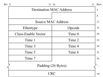
Fig.7shows the standard PFC control frame format. The time fields are used to store the time of the pause duration for the eight different CoSes. When the pause duration for a specific CoS ends, the paused CoS automatically resumes.
The unit of the pause time is quanta, which is 512-bit time on a used link. Because the link bandwidth used in our experi-
FIGURE 7. The format of the PFC control frame.
ments is 10 Gbps, a bit time is 0.1 nanosecond and a quanta is 51.2 nanoseconds. The maximum value for the time field is 65,535. Thus, the maximum pause time on the used link is about 3.4 milliseconds. In our experiments, we let PFFC and PFC use a half of the maximum value as the pause time, which is about 1.7 milliseconds. In PFC, actually no Opcode value is defined to represent a RESUME frame. When a time field is set to 0, it indicates to the upstream node that the corresponding CoS should be resumed even if its pause time is not over yet.
Although PFFC directly uses PFC to pause or resume an egress queue in the upstream node, this capability alone is not enough for PFFC to notify the upstream node to migrate a specific flow. The downstream node needs to convey the FID of the flow to be paused or resumed to the upstream node. However, from Fig. 7 there is no field defined for this purpose. Although there are some padding bytes that may be used to store the FID, we observed that when a PFC control frame is received by an upstream node, the control frame is ‘‘absorbed,’’ (i.e., directly processed and then dropped) by the port module without entering the IMAP of the upstream node. This means that although our P4 program can generate PFC control frames to pause or resume the PEQ in the upstream node that a specific flow is mapped to, our P4 program still needs to generate and send our own control frames to the upstream node to convey the FID information. Since this user-defined con- trol frame will not be ‘‘absorbed’’ by the port module but instead will be processed by our P4 program, we can use this information to migrate a specific flow in the upstream node.
Note that in PFFC all nodes use the same function to map the FID of a flow to the index of the shared PEQ that it uses.
As a result, to pause a specific flow in the upstream node, the downstream node can compute the FID and its corresponding index to know which shared PEQ in the upstream node is used by a specific flow. It then sets the corresponding time field in the generated PAUSE frame to the intended pause duration and sends the PAUSE frame to the upstream node to pause the PEQ shared by the flow.
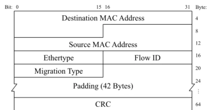
After performing the above step, the downstream node immediately sends a PFFC MIGRATE control frame to the upstream node to migrate the flow from the DEQ to this shared PEQ. To convey FID to the upstream node for flow migration, the downstream node generates and sends the PFFC control frame to the upstream node. Fig.8shows the format a custom PFFC control frame. The Flow ID field stores the FID of the flow to be migrated in the upstream node.
There are two types of migration: migrate and migrate-back.
The migrate type requests the upstream node to migrate the specified flow from the DEQ to the PEQ shared by the flow.
The migrate-back type requests the upstream node to migrate the flow back to the DEQ. As soon as receive the MIGRATE control frame, the migration is completed immediately since it simply changes the assignment of an egress queue to a flow (from DEQ to PEQ or in reverse).
To pause a specific flow in the upstream node, the down- stream node sends a PAUSE frame (which is a PFC con- trol frame with a non-zero timeout value) followed by a MIGRATE frame (which is a PFFC control frame of the migrate type). To resume a specific flow, the downstream node first sends a RESUME frame (which is a PFC control frame with a zero timeout value) and then immediately sends a MIGRATE-BACK frame (which is a PFFC control frame of the migrate-back type). The order of the two operations is particularly chosen to avoid packet reordering during the tiny transition period.
Upon receipt of the MIGRATE-BACK control frame for a paused flow, the flow is migrated immediately and the output port of new incoming packets for the flow is set to DEQ.
However, it is possible that the PEQ gets paused again before all packets of the migrated flow in the PEQ have been drained from the PEQ. In this case, the new packets of the migrated flow may be forwarded out of the switch via the DEQ before the old packets in the PEQ, which results in packet reordering and the flow may experience a short period of congestion.
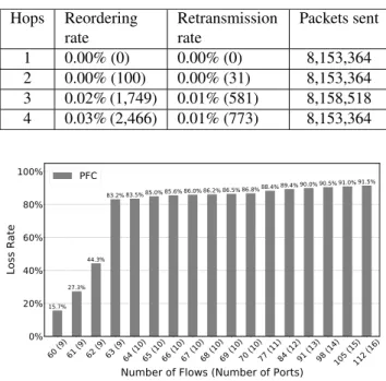
Fortunately, in our design, the delay for draining the PEQ packets is very short (less than 68.8 microseconds) and the measured extent of packet reordering is small, i.e., 0.03% as shown in Table2. The upper bound of the PEQ packet drain- ing time is computed as follows: The maximum buffer size of a PEQ Bqis 85,937 Bytes, which is computed by using Eqs.
(1) and (3) for a Tofino switch with 32 ports, 8 PEQ per port, and the buffer size of 22 MB. Since the port bandwidth of the switch is 10 Gbps, it takes at most 68.8 microseconds to drain all packets from the PEQ. In our experiments the average time period between a PEQ resume and the subsequent PEQ pause is larger than 68.8 microseconds, and this congestion spreading situation occurred infrequently, as evidenced by the measured 0.03% packet reordering ratio.
D. THE MANY-TO-ONE MAPPING ISSUE
In a network switch, the number of egress queues per output port is limited. This paper considers eight egress queues in a 10GbE port and 32 queues in a 100GbE port. Due to this hardware constraint, PFFC may have to map multiple flows
FIGURE 8. The format of the PFFC control frame.
to the same shared PEQ. Consequently, the same PEQ may be resumed for any of the flows that share it, causing a flow that should be paused for a longer time to be resumed earlier. To address this many-to-one issue, PFFC uses Xoffs and Xonsto control and protect the system buffer of a switch from overflowing. Therefore, even though a tiny number of packets may ‘‘leak’’ to the downstream node due to this phenomenon, they will be safely queued in the downstream node without being dropped. If the buffer usage of the flow in the downstream node is already higher than Xofff, when receiving these leaked packets, the downstream node will keep sending PAUSE frames to the upstream node for the flow. As a result, even though a paused flow may be resumed earlier by other flows, it will be paused again immediately.
Our experimental results (see SectionIV) show that PFFC can effectively pause hundreds of flows via the seven shared PEQs without causing any packet loss.
E. THRESHOLDS SETTINGS FOR PFC AND PFFC
Although PFC can protect an ingress queue from overflow- ing, SectionII-Dhas described a situation in which packets may still be dropped due to buffer overflow in an egress queue. In contrast, PFFC does not have this problem as it uses only the egress perspective to account and control the buffer usage of a flow and the switch.
The proper settings for PFFC Xoffs and Xons depend on the link bandwidth and the delays between an upstream and a downstream nodes, which include the signal propagation delay of the link (RTT) and the packet processing delay.
Such dependencies are universal. However, since the packet processing delay may vary for different types of hardware switches, and the link RTT may vary for cables of differ- ent lengths, the Xoffs and Xons parameter values should be selected through measurements for different types of hard- ware.
The best value for PFFC Xoffs is the minimal headroom buffer size that can absorb all the inflight packets at line rate (i.e., the link bandwidth) to avoid buffer overflow. The best PFFC Xons value is the minimal size of packets in the egress queue that can maintain 100% link utilization after the RESUME packet has been sent to the upstream node to resume its packet transmission. In this paper, we use a
set of iterative tests (in Section IV-B) to find proper settings for Xoffs and Xons to cover most traffic patterns. In our experiments, the best Xoffsvalue is 2.24 MB and the best Xons value is 1.2 MB.
The same values for Xofff and Xonf can be used for all flows. In our experiments, if the switch has a total buffer space of B and the number of flows passing it is N , we set Xofff and Xonf to 3B/N and B/N respectively for all flows. This policy allows a flow to have a buffer oversubscription ratio of 3:1. Since using the Xoffs and Xons mechanism already guarantees that no packets will be dropped due to buffer overflow, using 3:1 as the buffer oversubscription ratio allows the system buffer of the switch to be more efficiently utilized.
Alternatively, different sets of values can be used for different flows based on their bandwidth requirements or their relative priorities.
IV. PERFORMANCE EVALUATION
We have implemented PFFC in Inventec D10056 [13] P4 switches. These switches have 3.2 Tbps or 6.4 Tbps switching capacity, 32 1 × 100G ports (or 4 × 25G or 4 × 10G ports), and 21.3 MB of Packet Buffer memory. Experimental results show that PFFC can avoid or mitigate serious problems with PFC such as congestion spreading, deadlock, and packet loss.
We also evaluated the bandwidth overhead, performance, and scalability of PFFC on multi-hop network topologies.
The tested traffic patterns include multi-flow, multi-protocol (TCP vs. UDP), and multi-flow-type (elephant vs. mice) traffic patterns. The performance metrics include throughput, packet drop rate, flow completion time, link utilization, and bandwidth overhead. In summary, experimental results show that PFFC outperforms PFC in many aspects.
A. EXPERIMENTAL SETTINGS
Five hosts are used in the experiments and each has a 12-core Intel 3.2 GHz i7-8700 CPU and 16 GB RAM with Intel X710 network interface cards. These network interface cards support PFC. The hosts run Ubuntu Linux 18.04 operat- ing system. Since these network interface cards only sup- port 10 Gbps, we used a 40G QSFP+ to 4xSFP+ breakout optic cable to transform a 40G QSFP+ port of a switch to four 10GbE ports and then connect each 10GbE port to a host.
The P4 switch has eight ingress queues for every 10GbE port.
We use iperf version 2.0.13 [37] to generate UDP and TCP traffic in our experiments.
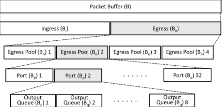
To make a fair comparison between PFC and PFFC, the buffer allocation for PFC and PFFC should be configured using the same structure. Fig.9 shows the buffer allocation structure used by the P4 switches [16]. We denote the Packet Buffer space as B, which is about 21.3 MB for the used P4 switches.
In Fig.9, the buffer space is divided into two parts: one for ingress traffic (Bi) and the other for egress traffic (Be), and each has B/2 buffer space.
B = Bi+ Be= B/2 + B/2 (1)
FIGURE 9. The buffer allocation structure used by the P4 switches used in our experiments.
The overall buffer space of the switch can be flexibly allocated to different ports and queues in a P4 switch or other hardware switches [17]. Here, we assume that the switch needs to process packets that may come from any input port and depart from any output port. For handling such a traffic pattern, we evenly divide the overall buffer space of the switch for each queue in each port for both ingress and egress traffic. In a 32-port switch, each port is allocated a buffer of size Bpfor its ingress traffic and egress traffic, respectively.
From Eq. (1),
Bp= Bi/32 = Be/32 = B/64 (2) Every ingress (egress) queue is allocated a buffer of size Bqin this evenly distributed buffer allocation. Because there are 8 ingress (and 8 egress) queues in each 10GbE port, from Eq. (2), we have
Bq= Bp/8 = B/512 (3)
In our experiments, we used 64Bq as the upper bound of buffer size for each egress queue in PFC and this means that we used a buffer oversubscription ratio of 64:1 for each egress queue in PFC. Compared with using Bqfor an egress queue, this high oversubscription ratio can greatly reduce the chances of packet dropping in an egress queue when PFC is used. However, as will be shown later, even using such a high oversubscription ratio, some packets were still dropped in a tested scenario when PFC was used.
We note that the specification [16] just explains the usage of the above buffer allocation structure and does not provide any recommendation about how to allocate buffer space to each port and queue. The above static provisioning will not be optimal for some traffic patterns where only a few input ports or output ports of a switch have heavy traffic to process.
We use this static provisioning to illustrate that packets may be dropped in PFC if the configured buffer provisioning does not fit the traffic patterns.
B. THRESHOLD SELECTION FOR PAUSE AND RESUME Before conducting experiments comparing PFC and PFFC, we first performed a series of tests to find a proper value for Xoffsto prevent packet loss in PFFC. The threshold selection for pause and resume is BDP (Bandwidth-Delay Product)
FIGURE 10. The network topologies used in our experiments.
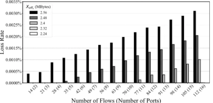
FIGURE 11. The packet loss rate vs. number of flows for Xoffsthreshold exploration. Each data point is the average value of 30 runs.
dependent. The BDP depends on the link bandwidth and the RTT between nodes. Although it is difficult to accurately measure the BDP inside the switch, we still can approximate the maximal value of BDP. The maximal value of BDP is lim- ited by hardware and is agnostic to traffic patterns. Fig. 10a shows the network topology (Topology I) that we used to explore a knee Xoffs value, which is the maximal value that does not cause packet loss.
We considered many-to-one (from 14:1 to 112:1) traf- fic patterns in this experiment. There are 4 sending hosts (NS1– NS4), 1 switch, and 1 receiving host (NR1). Each send- ing host has 4 ports and the receiving host has only one port.
This configuration supports up to 16 (4 hosts * 4 ports/host) packet generators, each of which is a software program using a different port on the sending hosts to send traffic to the single receiving host. The total number of flows from these sending hosts to the receiving host was varied from 14 to 112.
This was achieved by each packet generator launching 7 UDP flows (each using a different CoS) to the receiving host and we varied the number of used packet generators from 2 to 16.
The sending rate of each flow was set to 1 Gbps and the duration was 10 seconds. The reason why using UDP flows in this test was to ensure that these packet generators could steadily generate traffic at a fixed rate.
The buffer space for the output port that connects to NR1 was set to 64Bqas defined in SectionIV-A, which is 21.3/8 = 2.66 MB. Since all flows went through the same output port, for the buffer of this output port, we tested a range of threshold values for its Xoffs and only show the five values that are most close to the knee value in the figure. The five different Xoffs values are 2.56 MB, 2.48 MB, 2.4 MB, 2.32 MB, and 2.24 MB, respectively. Fig. 11shows the packet loss rates versus different numbers of flows (and the used ports) under these five threshold settings over the Topology I of Fig.10.
FIGURE 12. The link utilization vs. number of flows for Xonsthreshold exploration.
When the threshold value is lower than 2.24 MB, there is no packet loss. It means that the 0.42 = 2.66 − 2.24 MB headroom space is large enough to absorb inflight packets of the 112 UDP flows. Thus, in the following experiments, we used the value 2.24 MB for the Xoffsthreshold so that no packet will be dropped.
We also explored the minimum Xons value that does not cause any degradation of the utilization of the link between the switch and NR1. Fig.12shows the experimental results.
We consider five candidates Xons values and compare the link utilization under four different numbers of flows: 14, 35, 77, and 112, respectively. The link utilization decreases a bit when the Xons value is less than or equal to 0.8 MB.
When the Xonsvalue is greater than or equal to 1.2 MB, 100%
link utilization is achieved. Since this threshold should be as small as possible on the condition that the link utilization can maintain 100%, in all of our following experiments, we chose 1.2 MB as the Xonsthreshold.
The reason to find a maximum value for Xoffs without dropping any packet and a minimum value for Xons without lowering the link utilization is because in this way the fre- quency to cross these thresholds can be greatly reduced. As a result, the number of generated PAUSE and RESUME frames and thus the consumed link bandwidth for these frames can be greatly reduced. In SectionIV-H, our experimental results will compare the link bandwidth consumed by the control frames generated in PFC and PFFC, respectively.
C. SCALABILITY OF PFFC ON MULTI-HOP NETWORK TOPOLOGIES
Since PFFC is a per-hop per-flow scheme and will be used over multi-hop network topologies, it is important to see when PFFC is enabled whether the throughput of a flow may decrease as the number of hops increases. For this evaluation, we used the network topologies shown in Fig.13.
As can be seen, there are four topologies and they have 1, 2, 3 and 4 hops (i.e., intermediate switches) connected in a row, respectively. A sending host (NS1) sends traffic to the receiving host (NR1). On each topology, we connected
FIGURE 13. Multi-hop topologies: the number of hops (N) is ranged from 1 to 4.
FIGURE 14. The average throughput of TCP flows on multi-hop topologies.
another sending host (NS2) to Switch N so that the traffic of NS1and NS2merged in Switch N and generated congestion over the link from Switch N to NR1.
In the experiment, each of NS1and NS2used iperf to gener- ate 7 TCP flows each sending at 1 Gbps for 10 seconds. The total sending rate of these 14 flows exceeded the bandwidth of the 10 Gbps link between Switch N and NR1and caused congestion immediately. The optimal average throughput of these TCP flows should be 10 Gbps / 14 = 714 Mbps. Fig.14 shows that the average throughputs of these TCP flows over different numbers of hops are almost the same. These results show that the overhead of the design and implementation of PFFC is very small and thus the flow-controlled throughput of a TCP flow does not degrade when it traverses more and more hops on a network. From Fig. 14, one sees that there is a small difference between the average throughput of these TCP flows and the optimal value. This is because TCP header size is 20-byte long and a TCP header usually carries several TCP options. These headers and options consume the link bandwidth and cause the application-level average throughput of TCP flows to be slightly less than the optimal value.
The purpose of using TCP flows for this evaluation is to see whether PFFC may cause any packet loss or reorder during its operations. Due to the design of TCP congestion control algorithm, if any TCP packet is dropped, the TCP sender will immediately cut its sending rate by half to reduce its current sending rate. In addition, if there are packet reorders that cause more than three duplicate ACK packets to be sent to the TCP sender, the TCP sender will view that some of its packets have been dropped and thus also cut its current sending rate by a half. In short, a TCP flow is very sensitive to packet loss and reorder and its achieved throughput over time will fluctuate when some of its packets are intermittently dropped or reordered. From the results shown in Fig.14, one
TABLE 2.The extent of reordering and retransmission of TCP flows on multi-hop topologies.
FIGURE 15. Packet loss rate vs. number of flows in PFC.
sees that the average throughputs of TCP flows over different numbers of hops are very stable over time. The extent of packet reordering and retransmission are shown in Table2.
The reordering rate is the number of the reordered packets (in bracket) divided by the number of the packets sent. The extent of reordering is about 0.03% and the retransmission rate is less than 1% when the number of hops is up to 4. These results show that PFFC can serve TCP flows quite well.
D. PACKET LOSS IN MULTI-FLOW SCENARIOS
This subsection evaluates another scalability of PFFC to see whether PFFC can handle a large number of flows without dropping their packets. The network topology is shown in Fig. 10a (Topology I). As we did in SectionIV-B, we varied the number of UDP flows from 14 to 112 and the sending rate of each flow was set to 1 Gbps. (Note that the 7 UDP flows originated from the same packet generator used dif- ferent CoSes.) We compared the packet loss rate of PFFC with that of PFC. We set Xoffs to 2.24 MB and Xons to 1.2 MB for the PFFC experiments. For PFC, we allocated 64Bq (2.663 MB) buffer space to the egress queue of the output port that connects to NR1 and Bq (0.042 MB) buffer space to each ingress queue.
Experimental results show that no packet was dropped in PFFC when the number of flows was varied from 14 to 112.
This shows that PFFC can totally avoid packet dropping after its Xoffs and Xons thresholds have been calibrated. As for PFC, its packet loss rates under different numbers of flows are shown in Fig.15.
When PFC was used, some packets started to be dropped when the number of flows went beyond 59.
FIGURE 16. The network topology used for evaluating mice flows mixed with elephant flows.
We have explained why packets may be dropped in PFC in SectionII-D. Because in this experiment the egress queue used a buffer oversubscription ratio of 64:1, in theory as long as the number of flows does not exceed 64, PFC will not drop any packet. On the other hand, when the number of flows exceeds 64, some packets will be dropped without triggering the PFC flow control. However, even if the number of flows was smaller than 64, some packets may still be dropped.
Although in Fig.15there was some inconsistency in the boundary conditions, outside the boundary conditions, the measured packet loss rate under a specific number of flows in PFC is very close to what it should be. When there are N flows, since the sending rate of each flow is 1 Gbps, the total sending rate of these flows is N Gbps. Because the bandwidth of the bottleneck link is 10 Gbps, a (N − 10)/N percentage of sent packets will be dropped in the egress queue. For example, when N is 70, (N - 10)/N is 85.7%, which is very close to the measured packet loss rate.
E. FLOW COMPLETION TIME OF MICE FLOWS
Due to the fast flow control over hops, compared with end-to- end based methods, per-hop based flow control is considered a suitable scheme to handle mice flows when congestion occurs. This is because an end-to-end congestion control scheme requires at least a RTT to take effect; however, all of the packets of a mice flow may have been sent into the network within a RTT. In this experiment, we compared the performance of PFFC and PFC in processing mice flows using flow completion time (FCT) as the performance metric.
The network topology was configured as shown in Fig.16.
There are two sending hosts (NS1and NS2), three switches, and one receiving host (NR1). The bandwidth of all links is 10 Gbps.
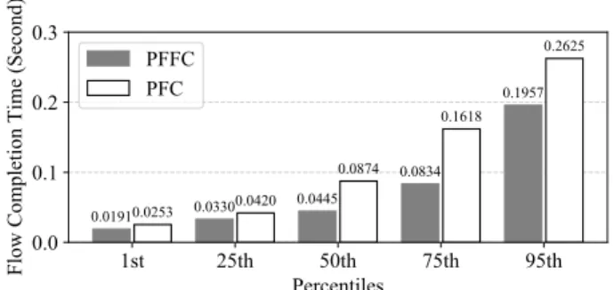
We considered the request/reply (mice flow) and file trans- fer traffic patterns. Each of NS1 and NS2 launched 7 UDP elephant flows sending at 1 Gbps to NR1 for 10 seconds to create congestion in Switch 1. After the first second, in each second of the following 5 seconds, each of NS1 and NS2 launched 56 mice flows to send a file to NR1, respectively.
Each mice flow is a TCP flow and its size is 10 KB. Fig.17 shows the 1st, 25th, 50th, 75th, and 95th percentile FCT over these mice flows when using PFC and PFFC as the flow control scheme, respectively. As can be seen, the 1st, 25th, 50th, 75th, and 95th percentile FCT of PFFC are shorter than those of PFC.
The reason why the average FCT of mice flows in PFFC is shorter than that in PFC is because in PFC there are only eight CoSes and thus multiple mice flows may need to be mapped to the same CoS. When PFC pauses a queue of a
FIGURE 17. The flow completion time of TCP mice flows mixed with UDP elephant flows.
FIGURE 18. The flow completion time of TCP mice flows mixed with TCP elephant flows.
specific CoS, all of the flows using that queue are paused, including mice flows. In contrast, in PFFC each mice flow is paused and resumed independently without being affected by other flows. As a result, the average FCT of mice flows in PFFC is shorter than that in PFC.
Fig.18shows the results of the second experiment, which used TCP flows as the elephant flows. As in the first exper- iment, the sender of each TCP elephant flow sent its traffic at 1 Gbps for 10 seconds. The results show that PFFC still performed better than PFC for mice flows when the elephant flows were TCP flows.
However, comparing Fig.17with Fig.18, one can see that the performance gains of PFFC over PFC in supporting mice flows were slightly reduced when the elephant flows were TCP flows. The reason is that in an upstream node, received TCP ACK packets delayed the processing of received PFFC control frames, thus increasing the FCT of mice flows in PFFC.
F. CONGESTION SPREADING EVALUATION
As explained in Section II-B, congestion spreading can occur in PFC. We used the following experiment to show this phenomenon. The used network topology is shown in Fig. 10b (Topology II).
We purposely configured the bandwidth of the link between Switch 2 and NR2to be only 1 Gbps and left other links to use their default bandwidth of 10 Gbps. We launched a 3 Gbps UDP flow from NS2to NR1 (Flow 1) and another 3 Gbps UDP flow from NS1 to NR2 (Flow 2). Because the