國
立
交
通
大
學
電信工程研究所
碩
士
論
文
無線隨意網路中針對接收端阻隔問題提出適應
性收端傳送協定之設計與分析
Design and Analysis of Adaptive Receiver Transmission
Protocols for Receiver Blocking Problem in Wireless Ad-Hoc
Networks
研 究 生:雷惟能
無線隨意網路中針對接收端阻隔問題提出適應性收端傳送
協定之設計與分析
Design and Analysis of Adaptive Receiver Transmission
Protocols for Receiver Blocking Problem in Wireless Ad-Hoc
Networks
研 究 生:雷惟能
Student:Wei-Neng Lei
指導教授:方凱田
Advisor:Kai-Ten Feng
國 立 交 通 大 學
電信工程研究所
碩 士 論 文
A ThesisSubmitted to Institute of Communications Engineering College of Electrical and Computer Engineering
National Chiao Tung University in Partial Fulfillment of the Requirements
for the Degree of Master of Science
in
Communications Engineering
March 2011
無線隨意網路中針對接收端阻隔問題提出適應性收端傳送
協定之設計與分析
學生:雷惟能
指導教授:方凱田
國立交通大學電信工程研究所碩士班
摘
要
分散式的無線網路環境中,因缺乏統籌管理無線資源的協調者,
因此媒體存取控制(MAC)協定之設計會是重要的議題。無線隨意網路
在吞吐量上的效能表現不彰,尤其接收端阻隔問題更進一步惡化無線
隨意網路的效能,因此本論文提出多重收端傳送機制(MRT)以及快速
網路配置向量截斷機制(FNT)來減緩接收端阻隔問題而不必額外再採
用控制通道以及傳輸天線。為了進一步提升 MRT 以及 FNT 之系統效能,
本論文尚提出適應性收端傳送協定(ART),以及可支援動態收端數目
調整之演算法(ART-DA)。爾後,本研究針對 ART 通訊協定建立數學模
型分析其效能,透過電腦模擬亦驗證了分析結果的準確性。此外,模
擬結果同時也與已存在對抗接收端阻隔問題的通訊協定進行比較,顯
示本研究提出的通訊協定以及搭配的演算法能更有效率的解決接收
端阻隔問題,提升整體無線隨意網路的系統吞吐量。
Design and Analysis of Adaptive Receiver
Transmission Protocols for Receiver Blocking
Problem in Wireless Ad-Hoc Networks
Student : Wei-Neng Lei Advisor : Kai-Ten Feng
Institute of Communications Engineering National Chiao Tung University
Abstract
Due to the lack of a centralized coordinator for wireless resource allo-cation, the design of medium access control (MAC) protocols is considered crucial for throughput enhancement in the wireless ad-hoc networks. The receiver blocking problem, which has not been studied in most of the MAC protocol design, can lead to severe degradation on the throughput perfor-mance. In this thesis, the multiple receiver transmission (MRT) and the fast NAV truncation (FNT) mechanisms are proposed to alleviate the receiver blocking problem without the adoption of additional control channels. The adaptive receiver transmission (ART) scheme is proposed to further enhance the system throughput with dynamic adjustment of the selected receivers. Analytical model is also derived to validate the effectiveness of the proposed ART protocol. Simulations are performed to evaluate and compare the pro-posed three protocols with existing MAC schemes. It can be observed that the proposed ART protocol outperforms the other schemes by both alleviat-ing the receiver blockalleviat-ing problem and enhancalleviat-ing the system throughput for the wireless multi-hop ad-hoc networks.
Contents
Chinese Abstract i English Abstract ii Acknowledgement iii Contents iv List of Figures vi 1 Introduction 1 2 Related Work 53 Network Model and Problem Statement 9
4 Proposed MAC Protocols 12
4.1 Multiple Receiver Transmission (MRT) Scheme . . . 12 4.2 Fast NAV Truncation (FNT) Scheme . . . 15 4.3 Adaptive Receiver Transmission (ART) Scheme . . . 18
4.3.1 Dynamic Adjustment of Parameter M in the ART
5 Throughput Analysis for ART Protocol 26
5.1 Network Scenario for Throughput Analysis . . . 28
5.2 Behavior of Tagged Node S . . . 30
5.2.1 S in Silent State . . . 32
5.2.2 S in Successful Transmission State . . . 35
5.2.3 S in Transmission Failure State . . . 36
6 Performance Evaluation 39 6.1 Performance Validation . . . 40 6.2 Observation on Parameter Mi . . . 41 6.3 Performance Comparison . . . 43 7 Conclusion 55 Bibliography 56
List of Figures
3.1 The schematic diagram for the receiver blocking problem: (a)
the network topology; (b) the timing diagrams of NAand NA’s
neighbors. . . 10 4.1 The data delivery process of the proposed MRT mechanism. . 14
4.2 The timing diagrams of N3, NA, NB, and NC under the
pro-posed FNT mechanism: The nodes (NA, N3) and (NB, NC)
are the two transmission pairs, where NA and NB are the two
corresponding source nodes. NA’s data transmission fails since
N3 is in the receiver blocking group B. Thanks to the
pro-posed FNT mechanism of truncating the NAV timer, NB can
initialize the channel contention and win the channel to start
the data transmission for NC. . . 16
4.3 The timing diagram for the ART protocol: If N3 cannot
cor-rectly receive the M-RTS packet from NA, it will set its NAV
timer as TLongEIF S in order not to interfere the CTS reception
of other nodes. After waiting for N3’s required CTS response
time along with TP IF S, ND replies with a CTS packet and
further triggers the data transmission. The other destination
4.4 The flow chart for dynamic adjustment of parameter Mi by adopting the ART protocol. . . 23 5.1 Two-dimensional Markov chain for contention-based state
tran-sition. . . 27 5.2 Hidden and common areas of a transmission pair in multi-hop
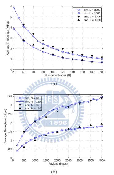
ad-hoc network. . . 29 6.1 Performance validation for ART protocol with M = 2: average
throughput versus number of nodes (top plot) and payload size (bottom plot). . . 48 6.2 Performance validation for ART protocol with M = 4: average
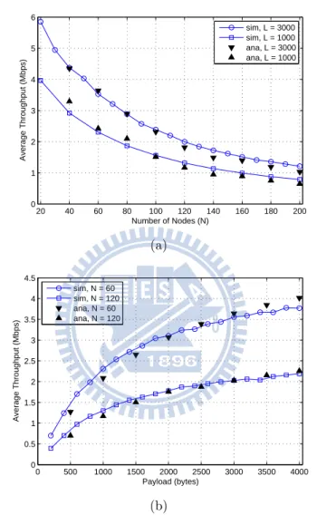
throughput versus number of nodes (top plot) and payload size (bottom plot). . . 49 6.3 Performance validation for IEEE 802.11a DCF protocol:
aver-age throughput versus number of nodes (top plot) and payload size (bottom plot). . . 50 6.4 Sensitivity analysis: average system throughput versus
de-creasing threshold T hd. . . 51
6.5 Average number of selected receivers Mi versus number of
to-tal nodes N. . . 51 6.6 Performance comparison: average throughput versus number
of nodes (top plot) and payload size (bottom plot). . . 52 6.7 Performance comparison: control overhead versus number of
nodes. . . 53 6.8 Performance comparison: average throughput versus
6.9 Performance comparison: average throughput versus maxi-mum velocity (m/s) (top plot) and maximaxi-mum pause time (ms) (bottom plot). . . 54
Chapter 1
Introduction
A wireless multi-hop network (WMN) [1] adopts wireless communication technologies to maintain connectivity and exchange messages between decen-tralized nodes in the multi-hop manners. This type of wireless networks are capable to perform self-creating, administering, and organizing the network connectivity. With the decentralized characteristics of the WMNs, feasible design of medium access control (MAC) protocol is considered important for performance enhancement. However, the connectivity between the network nodes are in general not guaranteed in the WMN, which incurs notorious ex-posed node and hidden node problems [2]. Some early attempts for resolving these problems in the literature [3–6] suggested the usage of request-to-send (RTS) and clear-to-send (CTS) mechanisms, which were later adopted by the IEEE 802.11 standards. The well-adopted IEEE 802.11 MAC protocol suite [7–10] can be employed in the WMNs since it has been specified to support decentralized operations called the ad-hoc mode.
However, it has been studied [11,12] that the deployment of ad-hoc mode in the IEEE 802.11 network does not always result in feasible performance. Even though the hidden node and exposed node problems can be partially
alleviated by adopting the distributed coordination function (DCF) in the IEEE 802.11-based protocols, an extended problem called receiver blocking or unreachability will be induced by the hidden node and exposed node prob-lems thereafter. The receiver blocking problem occurs when the intended destination is located within the coverage of an on-going transmission pair. The destination node is not able to response to the corresponding RTS packet from the sender since the destination will be in the silent state caused by ei-ther the virtual carrier sensing (VCS) or the physical carrier sensing (PCS). In such case, the source node which is outside the range of this on-going transmission pair will confront a series of connection failure with its desti-nation, which will result in the increase of unnecessary control overheads by initiating the RTS packets. The receiver blocking problem, which has not been addressed in the IEEE 802.11 standards, should deserve attention from research work since it will cause severe degradation on network throughput. The formal definition of the receiver blocking problem will be described in Chapter 3.
It has been investigated in several studies [13–20] regarding the severe per-formance degradation in ad-hoc networks. The dual-channel (DUCHA) [15] MAC protocol was proposed to alleviate the receiver blocking problem by adopting an additional channel for the transmission of control packets; while the data packet is transmitted in the data channel. The busy tone (BT) is adopted in the DUCHA protocol for the delivery of data packet; while the other nodes that hear the BT should suspend their attempts for data transmissions. The half-restraint carrier sense scheme (HCSS) [16] suggested a reduced carrier sensing threshold for receiver blocking avoidance. How-ever, smaller carrier sensing threshold, which results in less spatial reuse, can significantly cause the reduction of network throughput. Ye et al. [17] proposed a jamming-based MAC (JMAC) protocol to remove the hidden
ter-minal problem since each node will be equipped with two transceivers which independently operate in two separate channels, called the S-channel and the R-channel. As the destination is receiving the data packet on the S-channel, the other transceiver in the destination will broadcast the jamming signal on the R-channel which is considered a pseudo-noise in order to trigger the PCS mechanism from the heard neighbors. The channel will be marked as in the busy state such that the destination will not be interfered by its neighbors for the reception of data packets. However, each network node is required to install at least two transceivers in [15, 17] which is not always considered realistic due to hardware limitation and cost. In addition to the increase of hardware cost, the limited battery capacity in most mobile de-vices will constrain the adoption of multiple transceivers on each node since either the busy tone or the jamming signal can result in considerable energy consumption. Moreover, with the installation of multiple transceivers, the BT-based and JMAC schemes will not sufficiently utilize the advantages of spatial dimension which can cause poor multiplexing gain or diversity gain in a multiple-input multiple-output (MIMO) system [21]. The major reason is that the second transceiver is merely utilized for the transmission of either the busy tone or the jamming signal.
In this thesis, the multiple receiver transmission (MRT) and the fast NAV truncation (FNT) mechanisms are proposed to cope with the receiver blocking problem without adopting either additional control channels or transceivers. The MRT approach is proposed to provide additional oppor-tunities for the transmission to multiple receivers; while the FNT scheme reduces the duration of the network allocation vector (NAV) in order to provide channel accessing opportunities for the other nodes in the network. However, both the MRT and FNT schemes may suffer performance degrada-tion under specific network scenarios which lead to the proposal of adaptive
receiver transmission (ART) protocol in order to further enhance the net-work efficiency and channel utilization. The analytical model for throughput performance of the proposed ART protocol will be derived and further vali-dated with simulations. The performance evaluation of the proposed schemes will be performed and compared with the conventional IEEE 802.11a DCF protocol and other existing schemes via simulations. It will be shown that the receiver blocking problem can be effectively alleviated with the adoption of proposed MRT, FNT, and ART schemes. The network throughput can consequently be enhanced.
The rest of this thesis is organized as follows. In Chapter 2, a summary of related works is given. Chapter 3 describes the network model and the receiver blocking problem. The proposed MRT, FNT, and ART mechanisms are explained in Chapter 4; while the throughput analysis for ART protocol is derived in Chapter 5. Performance evaluation of these three schemes is shown in Chapter 6. Chapter 7 draws the conclusions.
Chapter 2
Related Work
The DUCHA protocol proposed in [15] is one of the earliest literature ap-proaching the receiver blocking problem which is inspired from the dual busy-tone multiple access (DBTMA) scheme. Haas et al. [22–24] presented the
DBTMA mechanism that utilized two out-of-band busy tones, including BTt
transmitted by the source node to inform all nodes within its transmission
range and BTrdelivered by the destination node to notify all the nodes within
the destination’s coverage. If a node overhears the busy tone signal, it must be kept in the silent state in order to avoid possible collision. Even thought this approach can well-address the hidden terminal problem, it is required to provide both an additional channel and an additional transceiver for imple-mentation. Several schemes have been proposed in [25–27] for performance enhancement based on the DBTMA protocol. In [25, 26], without signif-icant loss on throughput performance, the authors utilized only one busy tone channel to implement all the functionalities required by the DBTMA approach. The protocol proposed in [27] further improved the throughput performance by enlarging the carrier sensing range of the transmitter’s busy-tone channel.
Zhai and Fang [28] proposed a new MAC protocol, called short busy advertisements MAC (SBA-MAC), in which the sender inserts a few dummy bits in one data frame. During the time of dummy bits, the intended receiver transmits the short busy advertisements (SBA) over the same channel to clear the channel for data reception. The receiver will continue the reception of its remaining data packets afterwards. Therefore, it is only required for each node to equip one transceiver and the protocol can be operated in a single channel. However, the severe RTS packet collisions still remain unresolved which is considered the major challenge for ad-hoc networks. On the other hand, the eMAC protocol [29] is proposed based on a multiple access collision avoidance (AMACA) protocol [30] to deal with the receiver blocking problem. The eMAC-table contains partial topology information of a network node and is periodically exchanged between the neighbor nodes. Therefore, a node can maintain and utilize the dual-hop neighborhood graph to determine the best strategy for the transmission of individual communication pause (ICP) packet which solves the ICP broadcast storm problem in the original AMACA protocol. Note that the ICP packet is utilized when a network node is notified to be silent for a NAV duration and unfortunately becomes unreachable. Those unreachable nodes are provided with the opportunities to inform their one-hop neighbors about the upcoming unreachability by using the ICP packets, which are broadcast after the RTS/CTS negotiation and before the data transmission. Consequently, a network node will not establish the connection with those unreachable nodes after successfully receiving the ICP packets. Similar concepts are also adopted in [31].
Moreover, a enhanced IEEE 802.11 protocol that operates similar to the conventional DCF scheme is proposed in [32], which is called eDCF proto-col in this thesis for notation convenience. After sending the RTS packet to the intended receiver, the source node will set a timeout duration
wait-ing for the CTS response. If the CTS packet has not been received after the timeout period, the eDCF scheme will provide an additional opportunity to select another receiver from its queue to deliver data packet since this channel within the coverage of the source node has already been reserved. Therefore, the RTS packet is not wasted even the channel is erroneously re-served, and the source node will not repeatedly construct the connection to a blocked receiver. On the other hand, Jiang and Liew claimed that the pro-posed schemes in [33] are the first attempt for a comprehensive and rigorous study on both the hidden node and exposed node problems. This work indi-cates that these two problems are generally a tradeoff, which are considered difficult to be entirely removed in the network. The authors expressed the exposed node and hidden node problems based on several constraints, and these two problems can be removed if the designed constraints are not sat-isfied. The selective disregard of NAVs (SDN) scheme is proposed to break the constraints for the exposed node problem. The concept of SDN scheme is to turn off the PCS mechanism and the transmission is allowed only de-pending on the NAV period regardless of whether the medium is physically sensed busy or idle, which consequently resolves the exposed terminal prob-lem. However, the deactivation of PCS mechanism may potentially cause hidden node problem. Therefore, the hidden-node free design (HFD), inher-ited from [34], is proposed to compensate the drawbacks of SDN scheme by enlarging the range of PCS mechanism. However, the HFD scheme should operate with “restart mode” which is not utilized by default in most of the commercial IEEE 802.11 chips. The details about the “restart mode” can be referred in [34].
Furthermore, the work in [35] balanced the hidden node and exposed node problems by providing adequate power control to appropriately adjust the transmission, carrier sensing, and interference ranges. The approaches
pro-posed in [36–42] provide another category to alleviate the receiver blocking, the hidden node, and the exposed node problems by separating the traf-fic loads on multiple channels. However, the multichannel hidden terminal problem will be induced which can be a more complicate problem within the multichannel architecture. Finally, mathematical models on throughput analysis have been presented in [43–49] for contention-based channel access systems. These models will be referred in the performance analysis of pro-posed ART protocol, which will be described in Chapter 5.
Chapter 3
Network Model and Problem
Statement
Considering a set of nodes N = {Ni| ∀ i} within a two-dimensional
Eu-clidean plane, the locations of the set N are represented by the set P = {PNi| PNi = (xNi, yNi), ∀i}. It is assumed that all the nodes are homoge-neous and equipped with omnidirectional antennas under a single channel. The set of closed disks defining the transmission ranges of N is denoted as
D = {D(PNi, R) | ∀ i}, where D(PNi, R) = {x | kx − PNik ≤ R, ∀ x ∈ R
2}.
It is noted that PNi is the center of the closed disk with R denoted as the
radius of the transmission range for each Ni. Each node in the transmission
range D(PNi, R) can communicate with Ni by utilizing the IEEE
802.11-based MAC features for channel allocations, including PCS, VCS, and bi-nary exponential backoff (BEB) [50]. Moreover, the one-hop neighbor table for each Ni is defined as TNi = {Nk| PNk ∈ D(PNi, R), ∀ k 6= i}. The receiver blocking problem associated with the receiver blocking group are defined as follows.
R N 5 NB NC N 2 N 8 N 9 N 4 N 6 N 7 N 1 N A N 3 NE ND NF (a) N3 NA Blocking RTS1 RTS2 NAV3 (RTS3) RTS3 RTS4
TDIFS Tbackoff TNAV Tslot
NA’s neighbors NAV1 (RTS1) NAV2 (RTS2)
TTimeout
(b)
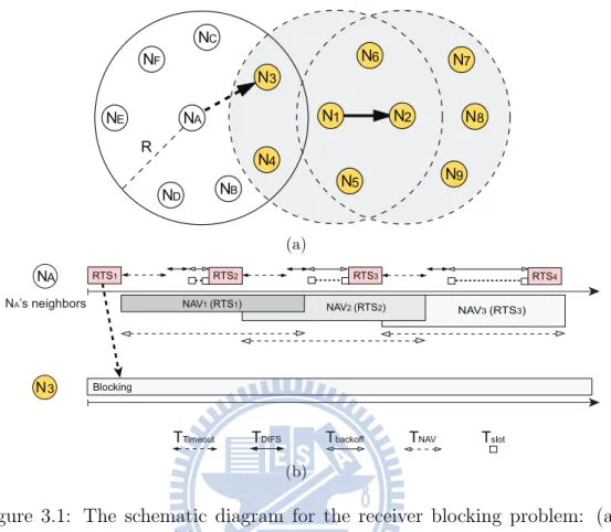
Figure 3.1: The schematic diagram for the receiver blocking problem: (a)
the network topology; (b) the timing diagrams of NA and NA’s neighbors.
includes all the transmitters and receivers, the receiver blocking group is
defined as B =SNi∈STNi since all the nodes in B are blocked either by the
carrier sensing mechanisms or due to the on-going packet transmission. Problem 1 (Receiver Blocking Problem). Let B be the receiver block-ing group within the network. The receiver blockblock-ing problem occurs while a
node Ni ∈ (N − B) intends to communicate with a node Nj ∈ B. Due to the
blocking nature of Nj, a large amount of useless connection-request packets
will be issued by Ni, which leads to the degradation of network throughput.
Fig. 3.1 illustrates the schematic diagram for the receiver blocking prob-lem with the network topology and the corresponding timing diagram. As
shown in Fig. 3.1(a), it is considered that N1 and N2 constitute the on-going transmission pair as identified by the solid arrow. The receiver blocking
problem happens if NA ∈ (N − B) intends to initiate a communication link
with N3 ∈ B, i.e. denoted by the dashed arrow. Based on Definition 1, the
receiver blocking group is obtained as B = {N1, ..., N9}, which lies within
the light gray region as in Fig. 3.1(a). Referring to Fig. 3.1(b), NA will
at-tempt to communicate with N3 by transmitting the RTS packet (i.e. RTS1)
after the successful channel contention. Based on the broadcast nature, NB
and NC will also receive the RTS1 packet and consequently set up their
corresponding NAV timers in order to refrain from accessing the channel,
i.e. TN AV = TCT S + TData+ TACK + 3TSIF S + 3Tprop. It is noted that the
subscript in each timing parameter is utilized to denote its corresponding meaning, i.e. TCT S, TData, TACK, TSIF S, and Tprop indicate the time dura-tions for the CTS packet, data packet, ACK packet, the short inter-frame
space, and the propagation delay respectively. Moreover, Tslot and TDIF S in
Fig. 3.1(b) represent the slot time of conventional IEEE 802.11 standard and the time duration for the DCF inter-frame space respectively; while the
parameter Tbackof f indicates the time interval for the current backoff window
of a node.
However, N3 will not respond to the RTS1 packet with a corresponding
CTS packet due to the PCS/VCS mechanisms. After a timeout Ttimeout =
TCT S+ TSIF S+ Tprop for waiting the CTS packet, NA will double its backoff
window and re-initiate to communicate with N3 by sending another RTS
packet, i.e. the RTS2 packet. In the meantime, NB and NC will refresh
their corresponding NAV timers based on the newly issued RTS2 packet as
in Fig. 3.1(b). Consequently, NA will result in a great amount of useless
retries of sending RTS packets, which prohibit NB and NC from contending
Chapter 4
Proposed MAC Protocols
For the purpose of alleviating the receiver blocking problem and its resulting drawbacks, three MAC schemes are proposed in this chapter, i.e. the mul-tiple receiver transmission (MRT), the fast NAV truncation (FNT), and the adaptive receiver transmission (ART) protocols. Note that the FNT scheme can be jointly implemented with the MRT mechanism in order to further enhance the network throughput.
4.1
Multiple Receiver Transmission (MRT)
Scheme
According to Definition 1, all nodes in the receiver blocking group B will
not respond to the node Ni ∈ (N − B). Therefore, the transmission of the
RTS packets from Ni will fail in constructing the communication links to the
nodes in B. It is noticed that the unsuccessful reception of the CTS packets
by Ni can be attributed to the factors as follows: (a) packet collisions; (b)
error reception of the CTS packet from the receiver; and (c) the receiver locating in the receiver blocking group B. If the failure of acquiring the CTS
packets is due to the factors (a) and (b), the conventional BEB method can be adopted to effectively resolve the drawbacks of the missing CTS packets by expanding the contention window and retransmitting the RTS packets. However, the BEB scheme will not suffice for alleviating factor (c), which will in general result in excessive and ineffective transmissions of the RTS packets.
One intuitive method to resolve factor (c) is to terminate the retrans-mission of the RTS packets since the RTS retries have no contribution in constructing the communication links with the node in B [29]. However, it
requires node Nito possess the information that the receiver is located within
B, which is considered inapplicable in realistic cases. The design concept of the proposed MRT technique is to increase the probability for selecting the destination that does not belong to the receiver blocking group B. Instead of merely transmitting the RTS packet to its original intended receiver in
B, Ni will also attempt to utilize the same RTS packet for constructing the
communication links with the other receivers which are not in the set B,
e.g. NC as in Fig. 3.1(a). The policy of the MRT scheme is to utilize the
the designed RTS packet (called M-RTS) that will be specified and destined
to more than one receiver, i.e. to the multiple receiver set RM where M
denotes the maximal number of receivers that will be specified within the M-RTS packet. In other words, additional receivers within the neighbor
ta-ble TNi will be randomly chosen to accept the M-RTS packet other than the
original targeting node that is located within the set B, i.e. the value of M is designed to be always greater than one. In comparison with the original RTS packet, there is an additional CTS responding list in the M-RTS packet. This CTS responding list records the order of response for each receiver in
RM, which ensures that the M receivers can arrange their CTS responses
NB NA M-RTSA CTSB ACKB TSIFS TSIFS {NB, NC} NC CTSC TSIFS TSIFS ACKC TSIFS NA’s neighbors NAV (M-RTSA) DATAAB DATAAC NAV(DATAAB) NAV(DATAAC) NAV (CTSB) NAV (CTSC) NB’s neighbors NC’s neighbors Ttimeout, MRT
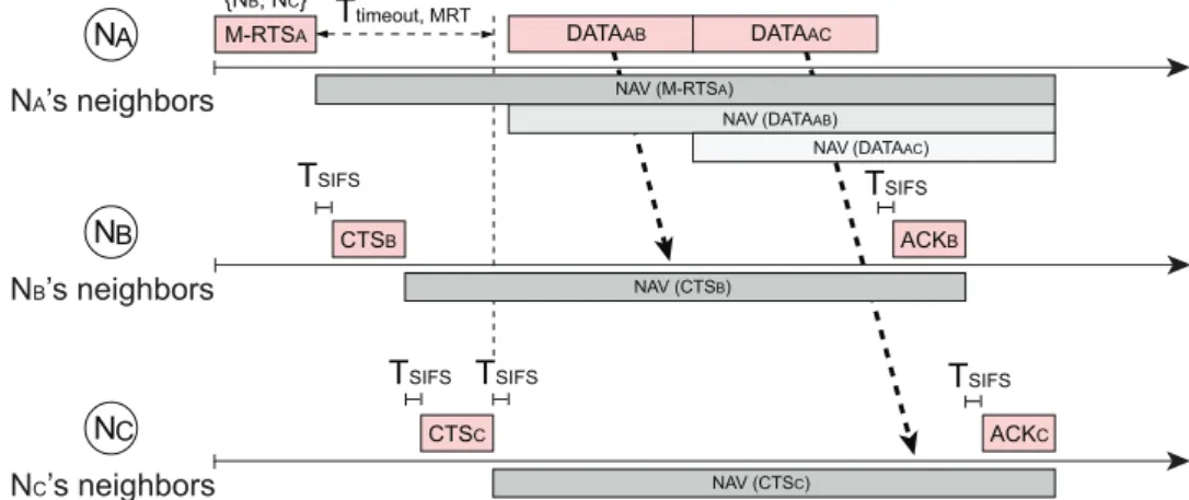
Figure 4.1: The data delivery process of the proposed MRT mechanism.
be blocked will be reduced from pf to pMf , where 0 ≤ pf < 1 is denoted
as the probability of transmission failure. Consequently, the receiver block-ing problem can be alleviated, which results in the enhancement of network throughput.
Fig. 4.1 shows the exemplified timing diagrams for the proposed MRT
scheme. It is assumed that NA wins the contention for channel access and is
ready to transmit its data packets, where the maximal number of receivers
within the multiple receiver set RM is chosen as M = 2. First of all, the
ideal case is considered where none of the selected node for RM is located
within the set B, e.g. RM = {NB, NC} as shown in Fig. 3.1(a). Based on
the proposed MRT scheme, NAwill therefore transmit an M-RTS packet, i.e.
the M-RTSA packet, which targets to both the two receivers NB and NC.
Under the case with non-blocking receivers, NB and NC will sequentially
feedback their CTS packets to NA with the time difference of TSIF S, where
the order of the CTS feedbacks is specified within the M-RTSApacket. After
the reception of the CTSB and CTSC packets, NA will start the delivery
of data packets to both NB and NC, respectively. Finally, the two receiver
i.e. ACKB and ACKC.
On the other hand, the receiver blocking problem can happen when one
of the selected nodes in RM belongs to the set B, e.g. RM = {NB, N3}.
Similar to the explanation as in Fig. 4.1, NAwill initiate the M-RTSApacket
that is addressed to both NB and N3. In this case, NA will not receive
the CTS packet from N3 since N3 is within the receiver blocking group B.
Therefore, the data packet towards NB will be transmitted after the end
of two CTS response time since the MRT protocol needs to wait for the
required response time from the selected destinations. Afterwards, NB will
send the ACK packet if it successfully receives the data packet from node
NA. In the case that NA does not receive any CTS feedbacks, NA will
re-initiate the contention process after a timeout period, which is M multiple of the original length defined in the conventional IEEE 802.11 protocol, i.e. Ttimeout,M RT = M · Ttimeout.
4.2
Fast NAV Truncation (FNT) Scheme
The design concept of the proposed FNT mechanism is to increase the prob-ability of channel contention under the occurrence of the receiver blocking problem. Note that the FNT scheme is designed independently but can be
combined with the MRT protocol. Considering the same case that NA
in-tends to transmit data packets to N3 as shown in Fig. 3.1(a), it can be
observed that NA will continue to win the channel contention on those
re-trials to N3 since all the other nodes will consistently be set at their NAV
states. As shown in Fig. 3.1(b), the NAV timer assigned by NA is longer
enough to prevent the other competitors from contending the channel during its retransmission to the node in receiver blocking group B. In order to pro-vide the channel accessing opportunities for the competitors, the proposed
N3 NC NB NA Blocking RTSA TDIFS Tbackoff Ttimeout, FNT Tslot NAV (DATAB) TSIFS ACKC NA’s neighbors RTSB DATAB NB’s neighbors NAV (RTSB) NC’s neighbors CTSC NAV (RTSB) NAV (RTSA) NAV (RTSA) NAV (RTSA) NAV (CTSC) NAV (DATAB)
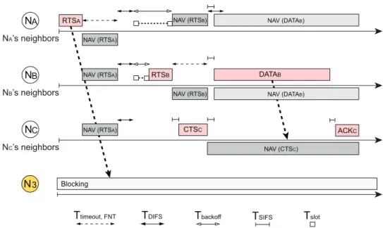
Figure 4.2: The timing diagrams of N3, NA, NB, and NC under the proposed
FNT mechanism: The nodes (NA, N3) and (NB, NC) are the two transmission
pairs, where NAand NB are the two corresponding source nodes. NA’s data
transmission fails since N3 is in the receiver blocking group B. Thanks to
the proposed FNT mechanism of truncating the NAV timer, NBcan initialize
the channel contention and win the channel to start the data transmission for NC.
FNT scheme reduces the NAV duration specified within the RTS packet to a shorter period of time which only protect until the end of current transmission of the CTS packet, i.e. a NAV duration of TN AV,F N T = TSIF S+ TCT S+ Tprop will be set within the RTS packet based on the FNT scheme.
As shown in Fig. 3.1(a) and Fig. 4.2, NA and NB are ready to contend
the channel for delivering their data packets to the destination nodes N3 and
NC, respectively. It is assumed that NA succeeds in the channel contention
and starts to communicate with N3 by sending the RTS packet, i.e. the
RTSA. Based on the proposed FNT scheme, both NB and NC will terminate
to a duration of TN AV,F N T. In the meantime, NA will continue to wait for the response, i.e. the CTS packet, that is supposed to be initiated from
N3. However, since N3 is located within the receiver blocking group B, none
of the CTS packet will be generated in the time interval of Ttimeout,F N T =
TSIF S + TCT S + Tprop by N3 in response to NA’s data transmission request.
It’s noted that the duration of Ttimeout,F N T and TN AV,F N T is truncated to
the same length in the proposed FNT protocol. Therefore, all the three
nodes NA, NB, and NC are free to contend the channel after the time period
Ttimeout,F N T, and both NAand NB will restart the channel contention process with equal channel accessing opportunities.
After the second round of channel contention as shown in Fig. 4.2, it is
assumed that NBsucceeds in the possession of the channel and constructs the
communication links with node NC by the transmission of the RTS packet,
i.e. the RTSB packet. Similarly, based on the FNT scheme, NA will set up
its NAV timer for a period of TN AV,F N T preventing itself from contending the
channel. As NB receives the CTS response from NC, NB will start to deliver
the data packets to NC after a period of time TSIF S. It is noticed that NA
will not interfere with the data delivery process of NB since the waiting time
of TDIF S for starting the channel contention process is comparably larger
than the waiting time TSIF S for initializing the delivery of data packets.
Furthermore, a NAV timer will be set to NA, i.e. NAV(DATAB) as shown in
Fig. 4.2, until the end of the packet delivery and acknowledgement between
NB and NC. Consequently, the receiver blocking problem can be effectively
4.3
Adaptive Receiver Transmission (ART)
Scheme
As described in section 4.1, the main concept of the MRT protocol is sim-ilar to the adoption of multi-user diversity in order to alleviate the effect of receiver blocking problem. However, the MRT scheme will confront the inefficiency problem due to the requirement to allow a large amount of se-quential feedbacks from the CTS packets. The major reason is that the MRT protocol has to wait for the response time of all the CTS packets from the selected destinations even though those nodes may not be able to reply with the CTS packets. This drawback can become more severe especially under the situation that the maximal number of receivers M specified within the M-RTS packet is designed to be a large value. Furthermore, as there are more than one receivers replying the CTS packets to the corresponding M-RTS transmission, the data transmission delay of these selected receivers will be increased since each receiver will spend time waiting for the data packets that are not destined to itself until the end of the entire data transmission.
As shown in Fig. 4.1, after NA receives the CTS responses from NB and NC
sequentially, the data packet DATAAB will firstly be delivered from NA to
NB. During this time period, NC has no choice but to wait until the end
of DATAAB transmission since the channel around NC’s coverage is already
reserved. Similarly, when NC is receiving the data packet DATAAC from NA,
NB can not acknowledge the data packet via the corresponding ACK packet
even though NB has already received its data packet. Therefore, the system
throughput can be limited by adopting the MRT scheme, which initiates the design of ART protocol.
In order to alleviate the problem associated with the MRT scheme, the proposed ART protocol is designed to enhance the system throughput by
NAV(DATAA) NA NA’s neighbors N3 ND ND’s neighbors NB M-RTSA TSIFS CTS2 TPIFS CTSM TPIFS TSIFS DATAA TSIFS ACK2 NAV(DATAA) NAV (CTS2) NAV(DATAA) NAV(DATAA) CTS3 TPIFS
NAV (Long EIFS) CTS1 NAV (M-RTSA) NF Ttimeout, ART 1st candidate: 2nd candidate: 3rd candidate: M-th candidate: Source node:
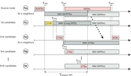
Figure 4.3: The timing diagram for the ART protocol: If N3 cannot correctly
receive the M-RTS packet from NA, it will set its NAV timer as TLongEIF S
in order not to interfere the CTS reception of other nodes. After waiting for
N3’s required CTS response time along with TP IF S, ND replies with a CTS
packet and further triggers the data transmission. The other destination
nodes will suspend their CTS feedbacks to NA.
conducting opportunistic CTS feedback. As shown in Fig. 4.3, NA initiates
the communication to the designated M receivers by broadcasting the M-RTS packet to its neighbors. Based on the order of receivers specified in the
M-RTS packet from NA, these M destinations are designed to potentially
reply their corresponding CTS packets to NA sequentially. One of the major
design parameters in the ART scheme is that the inter-frame space between
two CTS packets is modified from TSIF S to TSIF S + Tslot, which is
coinci-dentally equal to the point coordination function (PCF) inter-frame space TP IF S. Note that the adoption of TP IF S = TSIF S + Tslot in the proposed ART scheme will not conflict with the original centralized PCF coordination since only ad-hoc operations are considered in the network. The reason to
wait for additional Tslot within the TP IF S is to allow the receivers to verify if they should continue transmitting their CTS packets. Since each receiver
may not be able to hear the CTS feedbacks from other receivers to NA, an
elongated waiting time interval TP IF S is required for each receiver to
en-sure if there exists data transmission from NA to its pervious receiver after
a successful M-RTS/CTS negotiation. If a receiver does not hear the CTS
transmission associated with the data packet from NAto its previous receiver
after time TP IF S, the receiver will initiate the delivery of a CTS packet to
NA to request for data transmission. On the other hand, with successful
M-RTS/CTS handshaking between NA and the previous receiver, the data
packet from NA can therefore be transmitted after the short time duration
TSIF S. Consequently, by observing the on-going data transmission during
the additional Tslot time interval, the remaining receivers will suspend their
CTS feedbacks to NA in order to prevent unnecessary channel reservation
within their transmission ranges.
According to the mechanism as stated above, there is only one selected
receiver that replies its CTS packet back to NA, which consequently can
reduce the waiting time for other data packets that are not destined to itself. Similar to the other non-destination neighbors, those unselected destinations must wait for the NAV period until the end of on-going communication. Note that if a node can correctly receives the M-RTS packet, it will set up its NAV timer for the time period as
TNAV,ART = TSIF S + (M − 1)TP IF S+ M(TCT S+ Tprop) (4.1)
Furthermore, NA will re-initiate the contention process after Ttimeout,ART =
TN AV,ART if NA does not receive any CTS feedbacks, which is inherited from
designated to a specific receiver, the other selected receivers and
non-destination neighbors will refresh their NAV period to become TData+TSIF S+
TACK+ 2Tprop until the data has completed its transmission. Therefore, the
channel can be completely reserved within the transmission range of a source node, and the channel reservation becomes more flexible if the source node fails to establish the link with its receivers in this round of transmission.
In certain situations, the receivers may receive scrambled signals that can
not be decoded such that the M-RTS packet delivered from NA will not be
correctly received, e.g. the receiver N3 as shown in Fig. 4.3. The reason is
that these receivers are located in the receiver blocking group B where some neighbor nodes are simultaneously transmitting their packets. Therefore, in order not to interfere with either the CTS or ACK reception of other source
nodes, N3is designed to wait for a longer NAV duration as long EIFS that can
be obtained as TLongEIF S = TSIF S+(M −1)TP IF S+M(TCT S+Tprop)+TDIF S, which is extended from the conventional TEIF S = TSIF S+TCT S+Tprop+TDIF S
in the IEEE 802.11 system. Even if N3 can correctly receive the M-RTS
packet from NA, N3 may not be able to reply its corresponding CTS packet
since it can be NAVed by other on-going transmission in its neighborhood. N3
will be requested to refresh its NAV timer for TN AV,ART similar to the other
non-destination neighbors of NA. Furthermore, consider a node, e.g., NB,
correctly receives the M-RTS packet from a source node NA, and is notified
to be one of the M receivers. During the time interval between the end of
M-RTS transmission and before its CTS feedback, NBmay receive other M-RTS
or CTS packets from its neighbors before NB to broadcast its corresponding
CTS packet to the original source node NA. Under such situation, no matter
if NB will be informed to be the receiver from other source nodes, NB will be
requested to set its corresponding NAV timer according to the newly received M-RTS or CTS packet, which results in the termination of its original CTS
feedback.
Referring to Fig. 4.3 as an example, it is assumed that NA wins the
con-tention for channel access and transmits its M-RTS packet to M destinations.
All of NA’s neighbors will set their NAV period to be TN AV,ART. Consider
the case that N3 is unable to receive the M-RTS packet correctly from NA,
N3 will adjust its NAV timer as TLongEIF S in order not to interfere with the
other transmissions in the network. After waiting for the time durations of
both CTS1 transmission and TP IF S, ND will reply with its CTS feedback,
i.e. CTS2, to NAto request for data transmission. After observing the CTS2
packet from ND, the other nodes within the transmission range of ND will set
their NAV period to be TData+ TSIF S+ TACK + 2Tprop which is the same as
that in the duration field of conventional CTS packet. As NAhas received its
first CTS feedback from ND, NAwill begin the data transmission to ND after
the time duration of TSIF S. The CTS feedbacks from the other destinations,
i.e. from third candidate to M-th candidate, back to NA will therefore be
suspended. After the successful data transmission, the corresponding ACK
packet, i.e. ACK2, will be acknowledged from ND to NA.
4.3.1
Dynamic Adjustment of Parameter M in the ART
Protocol
The maximal number of receivers M for each sending node should be deter-mine in order to feasibly improve the network performance. The proposed ART scheme allows each node to maintain and dynamically adjust its own value of parameter M based on the real-time network environment. In order to further identify the dynamic behavior of parameter M, it will be
mod-ified as Mi where i = 1 to N with N denoting the total number of nodes
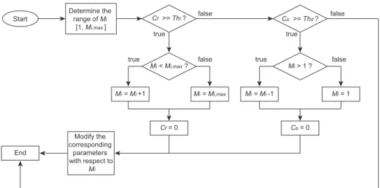
Determine the range of Mi [1, Mi,max] Start Cf >= Thi ? true true false false true false false true Modify the corresponding parameters with respect to Mi Mi < Mi,max ? Mi = Mi,max Mi = Mi +1 Cf = 0 Mi > 1 ? Mi = 1 Mi = Mi -1 Cs = 0 End Cs >= Thd ?
Figure 4.4: The flow chart for dynamic adjustment of parameter Mi by
adopting the ART protocol.
parameter Mi at every node in the network. As a node wins the contention
for channel access, e.g. node Ni, it will execute the algorithm to determine
the value of Mi in this transmission round before broadcasting its M-RTS
packet. First of all, the range of Mifor Niwill be determined for the dynamic
adjustment algorithm as [1, Mi,max], where the maximum value of this range
Mi,max can be obtained as
Mi,max = min{ωi, ni} (4.2)
Note that the parameter ni denotes the total number of neighbor nodes of
Ni. The other parameter ωi in (4.2) is utilized to limit the length of NAV
timer of Ni’s neighbor nodes not to exceed the best case of a successful data
transmission. In other words, according to (4.1), the NAV duration for those
unselected destination nodes after receiving the M-RTS packet from Ni will
be constrained to be TN AV,ART = TSIF S+ (ωi− 1)TP IF S+ ωi(TCT S+ Tprop) ≤ 3TSIF S+ TCT S+ TData+ TACK+ 3Tprop. Consequently, the parameter ωi will
be selected as ωi =
¹
2TSIF S+ TP IF S + TCT S+ TData+ TACK + 3Tprop TP IF S+ TCT S+ Tprop
º
(4.3) Note that the main purpose of the minimization in (4.2) is to intuitively
constrain the parameter ωi derived from NAV duration not to exceed the
total number of neighbors ni of Ni.
As depicted in the flow chat as shown in Fig. 4.4, the dynamic
adjust-ment of parameter Mi will first verify with an increasing threshold T hi to
determine if the current Mi should be increased or not. The verification
criterion is based on the number of continuously transmission failure of the
M-RTS packets from the previous rounds, which is denoted as Cf. If Cf is
greater than T hi, the adjustment algorithm considers this situation as
po-tential occurrence of receiver blocking problem. In general, the probability of continuously M-RTS collisions will be small since the BEB mechanism can adequately avoid packet collision if there does not exist the receiver blocking
problem. Therefore, the algorithm is designed to increase the current Mi
value such that there will be additional receivers to assist the data delivery process from the source node. As shown in the left part of the flow chat in
Fig. 4.4, the current Mi value will be verified whether it is less than the
maximum value Mi,max. If the condition is true, the current value of Mi will
be increased by one; otherwise, Mi is set equal to Mi,max. Consequently, the
counter Cf will be reset to zero to initiate another accumulation of M-RTS
transmission failures.
On the other hand, if Cf is less than the increasing threshold T hi, the
right part of the flow chart will be executed. In this case, the design
consid-eration is to examines whether the current Mi value should be decremented if
greater than the decreasing threshold T hd. The reason is that larger value of
Mi corresponds to excessive receivers are selected which can cause long delay
of the corresponding CTS feedbacks. If Cs ≥ T hd and Mi > 1, the current
Mi value will be counted down by one. Furthermore, if both Cf < T hi and
Cs < T hd, the current value of Mi will remain the same after executing the
adjustment algorithm. After the new Mi value is determined, the parameters
associated with Mi will be adjusted accordingly such as M-RTS packet size,
TN AV,ART, and TLongEIF S for node Ni. Afterwards, the ART protocol will
be adopted in Ni by broadcasting its M-RTS packet to those designated Mi
Chapter 5
Throughput Analysis for ART
Protocol
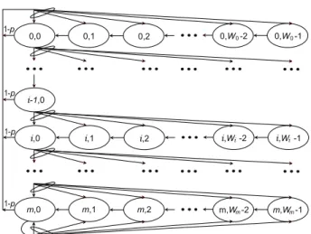
In this chapter, throughput analysis will be performed to provide the math-ematical modeling of proposed ART protocol. As shown in Fig. 5.1, Bianchi [43] has established a two-dimensional Markov chain to describe the state transition of a node where the state of each node is composed by the cur-rent retransmission stage and the curcur-rent backoff window size. Every data packet will be transmitted if the backoff window size is counted down to zero value. Let the probability p denote a source node that fails in transmitting its packet; while (1 − p) indicates the successful transmission probability. The two-dimensional Markov chain will return to its initial state if packet is successfully transmitted in each node. Otherwise, each node will increment its retransmission stage by one, and randomly determine its current backoff size from the corresponding contention window size based on the BEB mech-anism. Consider a saturated node that always has packets to transmit, the stationary transmission probability τ at a randomly selected time slot can
0,W -2 0
0,0 0,1 0,2 0,W -1 0
i,W -2 i
i,0 i,1 i,2 i,W -1 i
i-1,0 m,W -2m m,0 m,1 m,2 1-p 1-p 1-p 1-p m,W -1m
Figure 5.1: Two-dimensional Markov chain for contention-based state tran-sition.
be obtained from the two-dimensional Markov chain as
τ = 2(1 − 2p)
(1 − 2p)(W0+ 1) + pW0[1 − (2p)m]
(5.1)
where W0 denotes the minimal contention window size and m is maximum
number of retransmissions. Note that the parameter τ in (5.1) can also be translated as the probability that a node will transmit a frame in a given time slot; while (1-τ ) represents the probability for a node to remain silent. Detailed derivation can also be referenced from [43].
Therefore, the relationship in (5.1) between τ and p can be adopted to other random access based MAC protocol with saturated nodes, i.e., it can be applied to the proposed ART scheme. In order to solve this non-linear equation, an additional relationship between p and τ should be acquired such that both values can be solved by adopting numerical methods. In the following sections, how the stationary transmission probability τ affects the parameter p will be investigated in multi-hop ad-hoc network with the existence of hidden terminals.
5.1
Network Scenario for Throughput
Anal-ysis
As adopted in the IEEE 802.11 standard, the four-way handshaking mech-anism, i.e. RTS-CTS-DATA-ACK packet exchanges, is considered in the network scenario. Due to the hidden terminal problem, there is no guarantee to successfully transmit the CTS, DATA, and ACK packets in the multi-hop ad-hoc networks even if an RTS packet can be successful delivered. Fur-thermore, throughput performance can be severely degraded owing to the receiver blocking problem, which may requires an extra transmission hop for a packet to reach its destination. Note that routing algorithms can affect the system performance for determining the next transmission hop. In order to simplify the analysis, the proposed analytical model for the ART scheme will focus on the receiver blocking problem regardless of the adoption of spe-cific routing algorithm. All the data packets generated from a source node are assumed to be transmitted to its network neighbors and fixed number of specific receivers are randomly selected.
Moreover, all the network nodes are randomly distributed in a two-dimensional limited area. It is assumed that the active nodes always have data packets to deliver, and the packets size are considered to be the same. In order to simplify the analysis of the ART protocol, the transmission, sens-ing, and interference ranges for all the network nodes are assumed equal to R; while both the capture and shadowing effects are not considered for the network channel. The transmission failure at the receiver only occurs by packet collision while there are packets simultaneously delivered by other nodes which locate within the transmission range of the receiver. Owing to packet collision, those packets that cannot be decoded must be retrans-mitted. The transceiver equipped in each node operates in the half-duplex
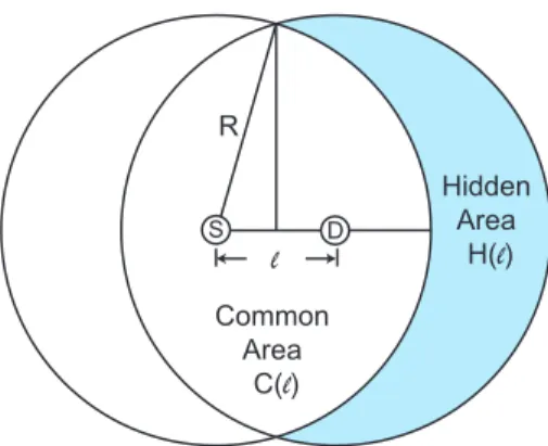
R Hidden Area H(l) l S D Common Area C(l)
Figure 5.2: Hidden and common areas of a transmission pair in multi-hop ad-hoc network.
mode, and each node only possesses a single omnidirectional antenna. As shown in Fig. 5.2, given the transmission pair S and D with distance ` apart, C(`) represents the common area intersected by the transmission ranges of S and D. On the other hand, consider a tagged node S, the hidden area H(`) is defined as the area enclosed by D’s transmission range excluding the common area C(`). Consider S as the transmitter for packet delivery, its M-RTS packet may not only incur packet collision within its own coverage but also suffer from transmission failure from potential hidden nodes in its hidden area H(`). Similarly, some neighbors of node D may not be able to correctly receive the CTS packet from the receiver D since there can exist a transmission pair in D’s hidden area, and the following data delivery between S and D will potentially be collided by these neighbor nodes of receiver D. Since the nodes are uniformly distributed in a constrained area with radius R, the distance between the tagged node S and its neighbor D will become a random variable L. Note that ` denotes one of the specific outcomes of L
variable L can be obtained as fL(`) = Z 2π 0 fL,Θ(`, θ)dθ = Z 2π 0
fX,Y(` cos θ, ` sin θ) · |J(`, θ)|dθ = 2`
R2 (5.2)
where fX,Y(x, y) = fX,Y(` cos θ, ` sin θ) = 1/(πR2). The parameters X and
Y are the random variables in the cartesian coordinates, L and Θ are the corresponding random variables in the polar coordinates, and J(`, θ) denotes the Jacobian matrix. In order to estimate the impact of hidden terminals, it is required to calculate the size of region where possible hidden terminals may exist. First of all, given the distance `, the common area can be computed
based on geometric relationship as C(`) = 2R2arccos( `
2R) − `(R2 − `
2
4)1/2. Consequently, the hidden area H(`) can be obtained as
H(`) = πR2− C(`) = πR2− 2R2arccos µ ` 2R ¶ + ` µ R2− `2 4 ¶1 2 (5.3)
Based on (5.2) and (5.3), the average value of hidden area Ahcan be expressed
as Ah = Z R 0 fL(`)H(`)d` = 2 R2 Z R 0 `H(`)d` (5.4)
and the average value of common area is acquired as Ac = πR2− Ah.
5.2
Behavior of Tagged Node S
The analytical model for throughput performance will be derived based on the standpoint of a tagged node. As shown in Fig. 5.2, the tagged node S intends to establish network connection with its neighbor node D. There are three possible states that can happen to node S in a given time slot as follows: (a) In the silent state, S may start to count down its backoff timer after the channel has been sensed idle. On the other hand, it can be
notified to freeze its backoff timer for a NAV duration due to either the PCS or VCS mechanism since there may exist either a transmitter or a receiver communicating within its coverage. (b) In the successful transmission state, after the backoff counter has reached zero, S will start its transmission and finally successfully transmit the data packets. (c) In the transmission failure state, S will suffer from packet collisions either via the other transmissions within its coverage or via the interference by the hidden nodes. Note that (5.1) can consequently be solved if the probability of failure transmission can be formulated while S is in the transmission failure state as (c). After formulating the probabilities for the tagged node S to be at one of the three states (a), (b), and (c), the throughput performance of S can therefore be calculated.
On the other hand, it is more complex to compute the successful transmis-sion probability since there are more events needs to be considered. Given the tagged node S initiating communication by broadcasting an M-RTS packet in a given time slot, the transmission will be successful to an arbitrary intended receiver D if and only if all of the following events hold: (i) There does not exist a node in D’s coverage that transmits the M-RTS packet during the same slot time; (ii) None of the nodes in D’s coverage transmits the CTS packet in the same slot time; (iii) None of the nodes are involved in
com-munication in the hidden area Ah of S during node S’s M-RTS transmission
time. Otherwise, receiver blocking problem can be occurred; and (iv) All the nodes in D’s coverage can correctly receive the CTS packet from D, and consequently setup their NAV vectors. Otherwise, these nodes can interfere with D by transmitting their M-RTS packets or replying the CTS packets. However, the interference from this type of nodes to D is in general consid-ered limited such that event (iv) will not be considconsid-ered in the performance analysis for simplicity purpose. Moreover, since the CTS packet is triggered
by its corresponding successfully transmitted M-RTS packet, the influence from the CTS transmission is relatively smaller than that from the M-RTS packets. Therefore, the effect from the CTS packets as stated in (ii) will not be considered in the analysis. In the next three subsections, the three states of a tagged node S in a particular time slot will be described as follows.
5.2.1
S in Silent State
There are three different network scenarios that need to be considered if the tagged node S is in the silent state as follows. Case 1: All nodes within the carrier sensing range of S will not conduct any packet transmission; Case 2: Only one node exists in the carrier sensing range of node S transmitting packets; and Case 3: Two or more nodes in the carrier sensing range of node S conduct packet transmission. With the definition of transmission probability τ , the probability for S to be in the silent state in a considered slot time becomes 1 − τ . The probability that all the neighbors of S are in the silent
state can consequently be obtained as (1 − τ )n−1, where n = ρπR2 represents
the average number of nodes in S’s carrier sensing range and ρ denotes the node density with unit as number of nodes per meter square. Therefore, the
probability for Case 1 to happen can be obtained as Pi,1 = (1 − τ )n. The
tagged node S will remain in the silent state for the duration of a slot time
Tslot, and consequently decrement its backoff window size by one.
Furthermore, consider the situation that there exists at least one node intending to transmit data within the carrier sensing range of S. The
corre-sponding conditional probability that only one node, e.g. Nx, is conducting
data transmission can be obtained as Pt=
(n − 1)τ (1 − τ )n−2
In Case 2, it is required to consider two scenarios that only node Nx can
either success or fail in its transmission. First of all, the probability for Nx
to successfully transmit its packet is acquired as Pi,2s =
£
(1 − τ )¡1 − (1 − τ )n−1¢Pt ¤
(1 − p) (5.6)
Note that p indicates the probability of failure transmission as was defined previously. On the other hand, after the backoff timer of S is suspended, the total time duration for this case can be acquired as
Ti,2s = TmRT S+ TCT S+ TData+ TACK + 3TSIF S + 3Tprop+ TDIF S (5.7)
where TmRT S and TCT S are the time durations for the M-RTS transmission
and the required average time for receiving a correct CTS packet, respec-tively. In order to obtain the value of TCT S, it is required to firstly calculate the probability of failure transmission caused by one of the M attempts from the M-RTS packet as
Pψ =
£
1 − (1 − τ )nc−1¤+ (1 − τ )nc−1P
hd (5.8)
where the first term represents the collision probability that at least one node
transmits in the common area Ac of Nx, and nc= ρAc indicates the average
number of nodes in Ac. The second term denotes the failure probability
caused by hidden terminals where the probability Phd can be calculated as
Phd= 1 − (1 − τ )nhζv with the parameter nh = ρAh representing the average
number of nodes in the hidden area of Nx. The probability Phdrepresents at
least one node in the hidden area Ahof Nxthat is not in the silent state during
the vulnerable period ζv, which can be computed as ζv =
l
TmRT S+Tprop+TSIF S Tslot
m
probability for all nodes within Nx’s hidden area which are in the silent state during the vulnerable period. It is assumed that the connection is established until the kth CTS packet is successfully transmitted, where k denotes a value of random variable K which follows the geometric distribution. Based on (5.8), the average number of CTS packets that are successfully transmitted can be obtained as nCT S = M X k=1 kPψk−1(1 − Pψ) (5.9)
Therefore, according to (5.9), the average time duration to receive a correct
CTS packet TCT S becomes
TCT S = nCT S(TCT S + Tprop) + (nCT S− 1)TP IF S (5.10)
Note that (5.10) can therefore be substituted into (5.7) for the computation
of Ti,2s. On the other hand, the other scenario is to consider the probability
that Nx fails in transmitting its packets, which can be expressed similar to
(5.6) as Pi,2f = £ (1 − τ )¡1 − (1 − τ )n−1¢P t ¤ p (5.11)
Based on the proposed ART scheme, the associated time duration for S to freeze its backoff timer can be acquired as
Ti,2f = TmRT S+ Tprop+ TN AV,ART + TDIF S (5.12)
where TN AV,ART is depicted in (4.1) for the proposed ART protocol.
Fur-thermore, in Case 3, the probability for two or more neighbor nodes of S to transmit data in a given time slot can be formulated as
Pi,3 = (1 − τ ) £
1 − (1 − τ )n−1¤(1 − P
Since S will receive more than one M-RTS packets simultaneously transmit-ting in the given time slot, only the scrambled signals will be acquired by S. In order to prevent from interfering the reception of either the CTS or the ACK packets at other source nodes, S is designated to setup its NAV period as long EIFS time duration. Therefore, the total required time interval for S in Case 3 by adopting the ART protocol can be acquired as
Ti,3 = TmRT S+ Tprop+ TLongEIF S (5.14)
Node S will continue to countdown its backoff timer after this time duration.
5.2.2
S in Successful Transmission State
The main target of proposed ART scheme is to adaptively increase the multi-user diversity in order to improve the throughput performance. With the transmission probability τ of S in a given slot time, a specific round of M-RTS transmission is considered unsuccessful only if all the attempts fail to receive the CTS packets from those M designated receivers. Therefore, the probability for S to be in the successful transmission state can be approxi-mated as
Ps ∼= τ (1 − PψM) (5.15)
where Pψ denotes the failure transmission probability caused by one of the M
attempts as can be obtained in (5.8). Note that the approximation in (5.15) holds under the condition that the number of receiver M is not too large such that the candidate receivers in the coverage area will not correlate with each other. Moreover, the total time duration for S to successfully transmit its data packet can be expressed as
where the average time duration for receiving a correct CTS packet TCT S can be obtained from (5.10).
5.2.3
S in Transmission Failure State
Consider the tagged node S stays in the transmission failure state given the transmission probability τ in a given time slot, there are two cases that can happen as follows: (a) Packet collision of the M-RTS transmission occurs in
the common area Ac of S, and (b) Failure transmission of M-RTS packet
happens from the influence of hidden nodes in Ah of S during the vulnerable
period ζv. In Case (a), the collision probability can intuitively be formulated
with the adoption of ART scheme as Pf,c∼= τ
£
1 − (1 − τ )nc−1¤M (5.17)
Note that the transmission failure in this case indicates that all of the M
transmission attempts to the designated receivers are collided in Ac of S
within a given slot time. The required time duration for the tagged node S to spend in this event can be obtained as
Tf,c = TmRT S + Tprop+ TLongEIF S (5.18)
On the other hand, if at least one of the M attempts is not collided in Ac of
S, the transmission failure can still occur due to the potential packet delivery
of hidden nodes in Ah of S. The failure transmission probability under this
circumstance, i.e. Case (b), can therefore be approximately computed as
Pf,h∼= τ " M X i=1 CiM£(1 − τ )nc−1¤i£1 − (1 − τ )nc−1¤M −iPi hd # (5.19)
where CM
i represents the binomial coefficient. The required time duration
for S to spend under this case can be expressed as
Tf,h= TmRT S+ Tprop+ Ttimeout,ART + TDIF S (5.20)
Finally, combining (5.17) and (5.19), the probability of transmission failure in a particular round of attempt can be expressed as
p = Pf,c+ Pf,h
τ (5.21)
which indicates the conditional probability that there is transmission fail-ure given the tagged node S transmits in a considered slot time. Therefore, combining the nonlinear equations (5.1) and (5.21), the parameters τ and p can be iteratively solved by adopting numerical methods. After the
fail-ure transmission probability p is obtained, the probability Pi,2s in (5.6) and
Pi,2f in (5.11) can also be determined. All the events discussed above are
summarized in Table 1.
The system throughput is defined as the number of bits in the data pay-load that are successfully transmitted per unit time, which represents the throughput per hop of a single node in the multi-hop ad-hoc networks. Based on the probabilities obtained in Table 1, the throughput Φ can consequently be acquired as
Φ = 8L · Ps
Pi,1Tslot+ Pi,2sTi,2s+ Pi,2fTi,2f + Pi,3Ti,3+ PsTs+ Pf,cTf,c+ Pf,hTf,h (5.22) where L denotes the total number of bytes in the payload. Furthermore, for evaluation purpose, the throughput performance of the conventional IEEE 802.11 multi-hop ad-hoc networks can also be acquired with several
modifi-TABLE 1
Summary for the probability of seven events at a considered slot of time Prob. Value of the probability Time Result
Pi,1 (1 − τ )n Tslot Backoff Pi,2s
£
(1 − τ )¡1 − (1 − τ )n−1¢P t
¤
(1 − p) Ti,2s Freeze its backoff timer Pi,2f
£
(1 − τ )¡1 − (1 − τ )n−1¢P t
¤
p Ti,2f Freeze its backoff timer Pi,3 (1 − τ )
£
1 − (1 − τ )n−1¤(1 − P
t) Ti,3 Freeze its backoff timer
Ps τ (1 − PψM) Ts Success
Pf,c τ
£
1 − (1 − τ )nc−1¤M Tf,c Failure due to collision Pf,h τh PMi=1CM i £ (1 − τ )nc−1¤i· £ 1 − (1 − τ )nc−1¤M −iPi hd
i Tf,h Failure due to hidden nodes
cations as follows. First of all, the parameter M = 1 and the probability p
in (5.6) and (5.11) is set to 0. The time duration Ti,2s in (5.7) is modified
to become Ti,2s = 3TSIF S + TRT S + TCT S+ TData+ TACK + 4Tprop+ TDIF S. The probability Ps in (5.15) is modified to Ps= τ (1 − τ )nc−1(1 − τ )nhζv, and
the corresponding Ts is revised to be same as the modified value of Ti,2s.
Fi-nally, the probability Pf,h in (5.19) is modified to be Pf,h = τ (1 − τ )nc−1Phd.
Note that the time duration TLongEIF S is degenerated to be TEIF S since the
parameter M is set to 1. Therefore, with the modifications as stated above, the system throughput for IEEE 802.11 ad-hoc networks can be obtained according the same formulation as (5.22).