國 立 交 通 大 學
機 械 工 程 學 系
碩 士 論 文
改善毛細泵吸迴路熱傳性能應用在電子冷卻
之實驗研究
An Experimental Study of Improving Heat Transfer Performance of
a Capillary Pumped Looped for Electronics Cooling
研 究 生:廖 峻 樟
指 導 教 授:林 清 發 博士
改善毛細泵吸迴路系統在電子冷卻上之實驗研究
Experimental Study of an Improved Capillary Pumped Looped System
for Electronics Cooling
研 究 生:廖 峻 樟 Student:Chun-Chang Liao
指導教授:林 清 發 Advisor:Tsing-Fa Lin
國立交通大學
機械工程學系
碩士論文初稿
A Thesis
Submitted to Institute of Mechanical Engineering
Collage of Engineering
National Chiao Tung University
In Partial Fulfillment of the Requirements
For the degree of
Master of Science
In
Mechanical Engineering
June 2007
誌 謝
時光飛逝,想當初才剛進交大,對於一切總是那麼地陌生。由於
學長與學弟的關心與幫助,讓我在這兩年的研究所生活過得非常充實
與開心。在這兩年的研究過程中,林清發老師的教學態度與研究精神
都是值得我學習的對象,相信對於往後不管是工作或是學習上都是很
有幫助的。然而,從一開始對於電子冷卻方面的知識一竅不通,直到
現在本論文的完成,要感謝的人很多,若不是有洪義祥學長的細心教
導,以及工研院劉家宏博士和張文瑞學長的從旁協助,可能我要花兩
倍甚至更多的時間才能完成。在此,我由衷的感謝老師、學長與學弟。
當然在研究室的兩年中,實驗室的好夥伴是不可少的,奎銘、凱
文與政陞不管在修課或做實驗的過程都是亦師亦友。其次對研究室成
員尚緯學長、汎鈞學長、建安學長、浚圩、永龍、壹龍、長志等人感
謝他們分享在實驗室的低潮與喜悅。
還要感謝清華大學工科系潘欽教授、清華大學動機系洪英輝教授
與成功大學機械系何清政教授在口試中提出各項建設性的建議,使得
本論文更趨於完備。
最後要感謝家人與所有好朋友在背後的的默默關心與支持,對於
每一個人的好,我一直心存感謝著。
改善毛細泵吸迴路熱傳性能應用在電子冷卻之
實驗研究
研究生:廖峻樟 指導教授:林清發 博士
國立交通大學機械工程學系
摘要
本實驗主要是研究並建立一套應用於電子冷卻的改良式毛細泵
吸迴路系統,數種改良蒸發器設計以增進熱傳性能的方法在本實驗中
被研究。這些方法包括在蒸氣溝槽的側面及底面製造粗糙面,使多孔
材料中的液體能潤濕溝槽表面以增加蒸發面積。其次,在蒸發器內部
加入一均熱片的影響也被探討。由針狀及平板鰭片構成的蒸氣通道對
毛細泵吸迴路性能的影響也進一步在本研究中探討。
本研究中使用一加熱面積為 30×30mm
2的加熱銅塊來模擬發熱中
的晶片,均熱片的加熱面積為 57×57mm
2並直接連接在加熱銅塊的上
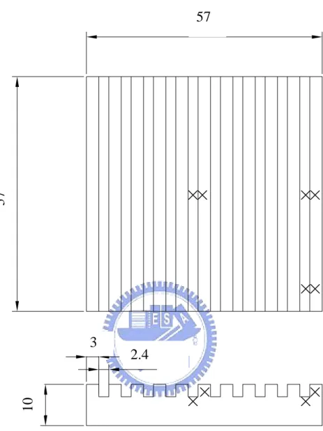
方。均熱片上方刻有 10 個溝槽供蒸氣流進蒸氣管路,每個溝槽的深
度為 3mm,寬度為 2.4mm,溝槽的尺寸和文獻[34]中未使用均熱片的
系統相同以便於比較。
實驗的結果指出工作流體的填充量會影響到整個系統的熱傳能
力,且在最高的散熱功率以及最低的熱阻值會發生在一最佳的充填
下降、最低熱阻值升高,增加蒸發器及冷凝器間的相對高度也會提高
整個系統的熱傳能力。另外,使用針狀鰭片來構成溝槽的設計並無法
增進整個系統的熱傳能力,使用均熱片則能有效的提升熱傳能力,在
溝槽的側面及底面使用粗糙面的設計亦能有效的增進整個系統的熱
傳能力。
An Experimental Study of Improving Heat Transfer Performance of
a Capillary Pumped Looped for Electronics Cooling
Student:Chun-Chang Liao
Advisor:Prof. Tsing-Fa Lin
Institute of Mechanical Engineering National Chiao Tung University
ABSTRACT
In the present study, an experimental capillary pumped loop for electronics cooling based on an improved system design is established. Several methods to improve the thermal performance of the loop by improving the evaporator design are investigated. These include roughing the vertical and bottom surfaces of the grooved channels to allow the liquid in the wick to wet the surfaces, which in turn greatly increases the surface area for the liquid vaporization. Besides, the possible heat transfer augmentation in the evaporator section through the use of a heat spreader on the heat dissipating chip is explored. Furthermore, the CPL performance difference between the vapor channels formed by plane fins and pin fins is also examined.
The heat dissipating chip with a surface area of 30×30mm2 is modeled by a heated copper plate of the same surface area in this study. The heat spreader, also a copper plate, is chosen to have a much larger surface area of 57×57 mm2, which is mounted directly on the heated copper plate. Ten grooved channels are machined on the surface of the heat spreader. Each grooved channel is 3mm in height and 2.4mm in width. The height and width of the channel are the same as that in the previous study [34] without using heat spreader.
height for the CPL with a given evaporator design. Besides, increasing or decreasing the liquid inventory from this optimal value causes a reduction in Qe,max and a raise in
Rth. Moreover, an increase in the relative height between the condenser and
evaporator results in a significant improvement in the CPL performance with a much higher Qe,max and a much lower Rth. Furthermore, there is no noticeable enhancement
in the heat transfer performance of CPL by using a pin fin block to form the grooved channels. However, the use of a large heat spreader in the evaporator can enhance the heat transfer performance greatly. Finally, roughing the vertical and bottom surfaces of the grooved channels can also significantly enhance the heat transfer performance of the CPL.
CONTENTS
ABSTRACT i
CONTENTS iii
LIST OF FIGURES v
LIST OF TABLE xiii
NOMENCLATURE xiv
CHAPTER 1 INTRODUCTION 1
1.1 Motive 1
1.2 Literature Review 2
1.3 Objective 7
CHAPTER 2 EXPERIMENTAL APPARATUS AND PROCEDURES 14
2.1 CPL Loop 14
2.2 Fluid Inventory Unit 16
2.3 Cold-Water Loop 16
2.4 Measurement Unit 17
2.5 Equipment 17
2.6 Experimental Procedures 18
2.7 Experimental Parameters 18
CHAPTER 3 DATA REDUCTION AND SIMPLE ANALYSIS 30
3.1 Data Reduction 30
3.2 Thermodynamic States and Heat transfer Limitation 31 3.3 System Pressure Drop Analysis 33
3.3.1 Maximum capillary pressure 34
3.3.2 Pressure drop in transport lines 34
3.3.3 Pressure drop in grooved channels 35
3.3.4 Pressure drop in wick structure 35
CHAPTER 4 RESULTS AND DISCUSSION 40
4.1 Performance Comparison between Vapor Channels Formed by Pin
Fins and Plane Fins 40
4.2 Installation of Heat Spreader 42
4.3 The Effects of Roughing the Surfaces of Grooved Channels 44
CHAPTER 5 CONCLUDING REMARKS 102
LIST OF FIGURES
Fig 1.1 Schematic of a Capillary Pumped Loop --- 12
Fig 1.2 Schematic of a typical evaporator design--- 13
Fig 2.1 Schematic diagram of experimental apparatus --- 21
Fig 2.2 Three-dimensional plots illustrating the CPL test loop --- 22
Fig 2.3 The detailed of structure evaporator --- 23
Fig 2.4 The details of the dimensions of the type 1 pin fin block.--- 24
Fig 2.5 The details of the dimensions of the type 2 pin fin block.--- 25
Fig 2.6 The details of the dimensions of the spreader grooved block. --- 26
Fig 2.7 Photographs of the roughing surface. --- 27
Fig 2.8 Photographs of the polyvinyl alcohol. --- 28
Fig 2.9 Locations of the thermocouples of the outer wall of the adiabatic cotton. --- 29
Fig 3.1 Schematics of a typical CPL system (a) and the corresponding P-T diagram at various locations (b)--- 38
Fig 4.1 Variations of mean evaporator temperature (a) and thermal resistance of the CPL (b) with the input power to the evaporator for the liquid inventory of 62% and relative height between condenser and evaporator of 0 cm for CPL with pin fin and plane fin blocks.--- 48
Fig 4.2 Variations of mean evaporator temperature (a) and thermal resistance of the CPL (b) with the input power to the evaporator using type-1 pin fin block for relative height between condenser and evaporator of 0 cm. --- 49
Fig 4.3 Variations of mean evaporator temperature (a) and thermal resistance of the CPL (b) with the input power to the evaporator using type-1 pin fin block for liquid inventory of 50% and relative height between condenser and evaporator of 0 cm.--- 50 Fig 4.4 Variations of mean evaporator temperature (a) and thermal resistance of the
CPL (b) with the input power to the evaporator using type-1 pin fin block for liquid inventory of 62% and relative height between condenser and
Fig 4.5 Variations of mean evaporator temperature (a) and thermal resistance of the CPL (b) with the input power to the evaporator using type-1 pin fin block for liquid inventory of 75% and relative height between condenser and evaporator of 0 cm.--- 52 Fig 4.6 Variations of mean evaporator temperature (a) and thermal resistance of the
CPL (b) with the input power to the evaporator using type-1 pin fin block for liquid inventory of 62% and relative height between condenser and evaporator of 0 cm.--- 53 Fig 4.7 Variations of mean evaporator temperature (a) and thermal resistance of the
CPL (b) with the input power to the evaporator using type-1 pin fin block for liquid inventory of 62% and relative height between condenser and evaporator of 5 cm.--- 54 Fig 4.8 Variations of mean evaporator temperature (a) and thermal resistance of the
CPL (b) with the input power to the evaporator using type-1 pin fin block for liquid inventory of 62% and relative height between condenser and evaporator of 10 cm. --- 55 Fig 4.9 Variations of mean evaporator temperature (a) and thermal resistance of the
CPL (b) with the input power to the evaporator using type-1 pin fin block for liquid inventory of 62% for different relative heights between evaporator
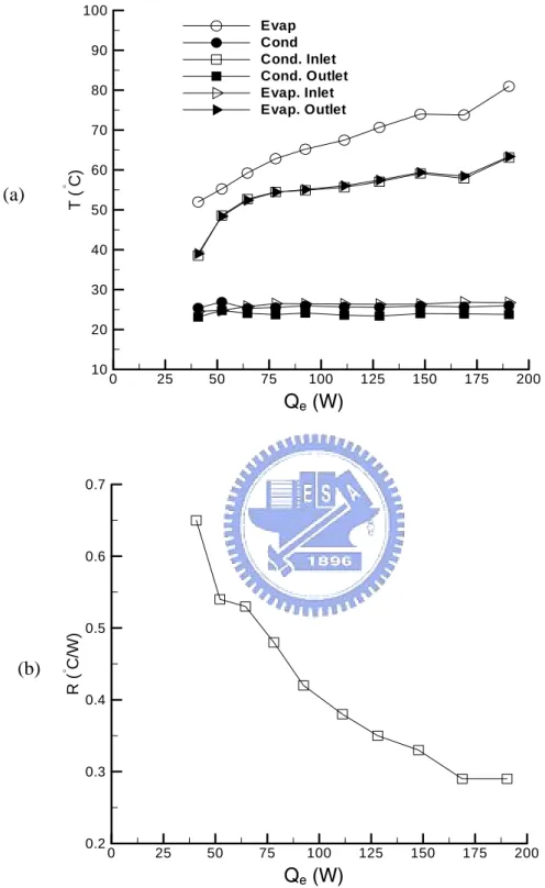
and condenser. --- 56 Fig 4.10 Variations of temperatures at selected locations (a) and thermal resistance of
the CPL (b) with the input power to the evaporator using heat spreader for liquid inventory of 71% and relative height between condenser and evaporator of 0 cm.--- 57 Fig 4.11 Variations of temperatures at selected locations (a) and thermal resistance of
the CPL (b) with the input power to the evaporator using heat spreader for liquid inventory of 65% and relative height between condenser and evaporator of 0 cm.--- 58 Fig 4.12 Variations of temperatures at selected locations (a) and thermal resistance of
the CPL (b) with the input power to the evaporator using heat spreader for liquid inventory of 59% and relative height between condenser and evaporator of 0 cm.--- 59
Fig 4.13 Variations of temperatures at selected locations (a) and thermal resistance of the CPL (b) with the input power to the evaporator using heat spreader for liquid inventory of 53% and relative height between condenser and evaporator of 0 cm.--- 60 Fig 4.14 Variations of temperatures at selected locations (a) and thermal resistance of
the CPL (b) with the input power to the evaporator using heat spreader for liquid inventory of 50% and relative height between condenser and evaporator of 0 cm.--- 61 Fig 4.15 Variations of temperatures at selected locations (a) and thermal resistance of
the CPL (b) with the input power to the evaporator using heat spreader for liquid inventory of 47% and relative height between condenser and evaporator of 0 cm.--- 62 Fig 4.16 Variations of temperatures at selected locations (a) and thermal resistance of
the CPL (b) with the input power to the evaporator using heat spreader for liquid inventory of 44% and relative height between condenser and evaporator of 0 cm.--- 63 Fig 4.17 Variations of mean evaporator temperature (a) and thermal resistance of the
CPL (b) with the input power to the evaporator using heat spreader for various liquid inventories for relative height between condenser and evaporator of 0 cm.--- 64 Fig 4.18 Variations of temperatures at selected locations (a) and thermal resistance of
the CPL (b) with the input power to the evaporator using heat spreader for liquid inventory of 59% and relative height between condenser and evaporator of 0 cm.--- 65 Fig 4.19 Variations of temperatures at selected locations (a) and thermal resistance of
the CPL (b) with the input power to the evaporator using heat spreader for liquid inventory of 59% and relative height between condenser and evaporator of 5 cm.--- 66 Fig 4.20 Variations of temperatures at selected locations (a) and thermal resistance of
Fig 4.21 Variations of mean evaporator temperature (a) and thermal resistance of the CPL (b) with the input power to the evaporator using heat spreader for various relative heights between evaporator and condenser for liquid inventory of 59%.--- 68 Fig 4.22 Variations of temperatures at selected locations (a) and thermal resistance of
the CPL (b) with the input power to the evaporator using heat spreader for liquid inventory of 47% and relative height between condenser and evaporator of 0cm.--- 69 Fig 4.23 Variations of temperatures at selected locations (a) and thermal resistance of
the CPL (b) with the input power to the evaporator using heat spreader for liquid inventory of 47% and relative height between condenser and evaporator of 5cm.--- 70 Fig 4.24 Variations of temperatures at selected locations (a) and thermal resistance of
the CPL (b) with the input power to the evaporator using heat spreader for liquid inventory of 47% and relative height between condenser and evaporator of 10cm. --- 71 Fig 4.25 Variations of mean evaporator temperature (a) and thermal resistance of the
CPL (b) with the input power to the evaporator using heat spreader for various relative heights between evaporator and condenser for liquid inventory of 47%.--- 72 Fig 4.26 Variations of the maximum allowable power input with the liquid inventory
for the relative height between condenser and evaporator of 0 cm for CPL
with and without the heat spreader installed in the evaporator.--- 73 Fig 4.27 Variations of mean evaporator temperature (a) and thermal resistance of the
CPL (b) with the input power for the system with and without heat spreader and relative height between condenser and evaporator of 0 cm at the optimal
liquid inventory. --- 74 Fig 4.28 Variations of the maximum allowable power input with the liquid inventory
for the relative height between condenser and evaporator of 5 cm for CPL
with and without the heat spreader installed in the evaporator.--- 75 Fig 4.29 Variations of the maximum allowable power input with the liquid inventory
with and without the heat spreader installed in the evaporator.--- 76 Fig 4.30 Variations of temperatures at selected locations (a) and thermal resistance of
the CPL (b) with the input power to the evaporator using heat spreader with the surface roughing on the grooved channels for the liquid inventory of
47% and relative height between condenser and evaporator of 0 cm. --- 77 Fig 4.31 Variations of temperatures at selected locations (a) and thermal resistance of
the CPL (b) with the input power to the evaporator using heat spreader with the surface roughing on the grooved channels for the liquid inventory of
50% and relative height between condenser and evaporator of 0 cm. --- 78 Fig 4.32 Variations of temperatures at selected locations (a) and thermal resistance of
the CPL (b) with the input power to the evaporator using heat spreader with the surface roughing on the grooved channels for the liquid inventory of
53% and relative height between condenser and evaporator of 0 cm. --- 79 Fig 4.33 Variations of temperatures at selected locations (a) and thermal resistance of
the CPL (b) with the input power to the evaporator using heat spreader with the surface roughing on the grooved channels for the liquid inventory of
59% and relative height between condenser and evaporator of 0 cm. --- 80 Fig 4.34 Variations of mean evaporator temperature (a) and thermal resistance of the
CPL (b) with the input power to the evaporator using heat spreader with the surface roughing on the grooved channels for various liquid inventories for
the relative height between condenser and evaporator of 0 cm. --- 81 Fig 4.35 Variations of the maximum allowable power input with the liquid inventory
for the relative height between condenser and evaporator of 0 cm for CPL with and without the surface roughing on the vertical and bottom surface of
the grooved channels in the evaporator. --- 82 Fig 4.36 Variations of mean evaporator temperature (a) and thermal resistance of the
CPL (b) with the input power for the relative height between condenser and evaporator of 0 cm at the optimal liquid inventories for the CPL with and
the CPL (b) with the input power to the evaporator using heat spreader with the surface roughing on the grooved channels for the liquid inventory of
50% and relative height between condenser and evaporator of 0 cm. --- 84 Fig 4.38 Variations of temperatures at selected locations (a) and thermal resistance of
the CPL (b) with the input power to the evaporator using heat spreader with the surface roughing on the grooved channels for the liquid inventory of
50% and relative height between condenser and evaporator of 5 cm. --- 85 Fig 4.39 Variations of temperatures at selected locations (a) and thermal resistance of
the CPL (b) with the input power to the evaporator using heat spreader with the surface roughing on the grooved channels for the liquid inventory of
50% and relative height between condenser and evaporator of 10 cm.--- 86 Fig 4.40 Variations of mean evaporator temperature (a) and thermal resistance of the
CPL (b) with the input power to the evaporator using heat spreader with the surface roughing on the grooved channels for various relative heights between evaporator and condenser for the liquid inventory of 50%. --- 87 Fig 4.41 Variations of temperatures at selected locations (a) and thermal resistance of
the CPL (b) with the input power to the evaporator using heat spreader with the surface roughing on the grooved channels for the liquid inventory of
47% and relative height between condenser and evaporator of 0 cm. --- 88 Fig 4.42 Variations of temperatures at selected locations (a) and thermal resistance of
the CPL (b) with the input power to the evaporator using heat spreader with the surface roughing on the grooved channels for the liquid inventory of
47% and relative height between condenser and evaporator of 5 cm. --- 89 Fig 4.43 Variations of temperatures at selected locations (a) and thermal resistance of
the CPL (b) with the input power to the evaporator using heat spreader with the surface roughing on the grooved channels for the liquid inventory of
47% and relative height between condenser and evaporator of 10 cm.--- 90 Fig 4.44 Variations of mean evaporator temperature (a) and thermal resistance of the
CPL (b) with the input power to the evaporator using heat spreader with the surface roughing on the grooved channels for various relative heights between evaporator and condenser for the liquid inventory of 47%. --- 91 Fig 4.45 Variations of temperatures at selected locations (a) and thermal resistance of
the CPL (b) with the input power to the evaporator using heat spreader with the surface roughing on the grooved channels for the liquid inventory of
53% and relative height between condenser and evaporator of 0 cm. --- 92 Fig 4.46 Variations of temperatures at selected locations (a) and thermal resistance of
the CPL (b) with the input power to the evaporator using heat spreader with the surface roughing on the grooved channels for the liquid inventory of
53% and relative height between condenser and evaporator of 5 cm. --- 93 Fig 4.47 Variations of temperatures at selected locations (a) and thermal resistance of
the CPL (b) with the input power to the evaporator using heat spreader with the surface roughing on the grooved channels for the liquid inventory of
53% and relative height between condenser and evaporator of 10 cm.--- 94 Fig 4.48 Variations of mean evaporator temperature (a) and thermal resistance of the
CPL (b) with the input power to the evaporator using heat spreader with the surface roughing on the grooved channels for various relative heights between evaporator and condenser for the liquid inventory of 53%. --- 95 Fig 4.49 Variations of the maximum allowable power input with the liquid inventory
for the relative height between condenser and evaporator of 5 cm for CPL with and without the surface roughing on the vertical and bottom surface of
the grooved channels in the evaporator. --- 96 Fig 4.50 Variations of the maximum allowable power input with the liquid inventory
for the relative height between condenser and evaporator of 10 cm for CPL with and without the surface roughing on the vertical and bottom surface of
the grooved channels in the evaporator. --- 97 Fig 4.51 Variations of mean evaporator temperature (a) and thermal resistance of the
CPL (b) with the input power to the evaporator using heat spreader with the surface roughing on the grooved channels for terminating at various for the liquid inventory of 47% and relative height between condenser and
evaporator of 0 cm.--- 98
evap
T
Fig 4.52 Variations of mean evaporator temperature (a) and thermal resistance of the CPL (b) with the input power to the evaporator using heat spreader with the
for the liquid inventory of 50% and relative height between condenser and
evaporator of 0 cm.--- 99 Fig 4.53 Variations of mean evaporator temperature (a) and thermal resistance of the
CPL (b) with the input power to the evaporator using heat spreader with the surface roughing on the grooved channels for terminating at various for the liquid inventory of 53% and relative height between condenser and
evaporator of 0 cm.--- 100
evap
T
Fig 4.54 Variations of the maximum allowable power input with the liquid inventory for terminating at various for CPL with the surface roughing on the
vertical and bottom surface of the grooved channels in the evaporator.--- 101
evap
LIST OF TABLES
Table 1.1 Summary of results in previous CPL studies--- 9
Table 2.1 Geometric and material characteristics of present CPL system--- 19
Table 2.2 Experimental parameters--- 20
Table 3.1 Summary of the uncertainty analysis--- 38
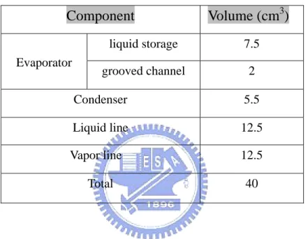
Table 4.1 Volume of each component in the CPL system without heat spreader--- 46
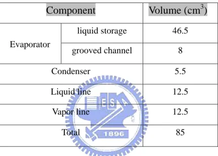
Table 4.2 Volume of each component in the CPL system with heat spreader in evaporator--- 47
NOMENCLATURE
A cross sectional area, m2p c specific heat, J/kg℃ D diameter of tube, m f friction factor F dimensionless factor g gravitational acceleration, m/s2
Hg relative height between evaporator and condenser, m
h relative height, m, or heat transfer coefficient, W/m2℃
hn,t heat transfer coefficient from the top of evaporator section to ambient, W/m2℃
hn,r heat transfer coefficient from the radial surface of evaporator section to ambient, W/m2℃
hn,b heat transfer coefficient from the bottom of evaporator section to ambient, W/m2℃
K permeability, m2
k thermal conductivity, W/m K
I measured current from DC power supply, A L length, m, or liquid inventory
•
m mass flow rate, kg/s N number of grooved channel
P pressure, kPa
Q heat load, W
R thermal resistance, ℃/W
Re Reynolds number
T temperature,℃
V measured voltage from DC power supply; velocity, m/s z thickness of wick, m
Greek Symbols
∆P pressure drop, kPa
∆T temperature difference, ℃ ρ density, kg/m3
σ surface tension, N/m
δ cotton gauze layer thickness, m μ viscosity, N-S/m2
ε porosity, %
l thickness of wick θ contact angle Subscripts
cap capillary term
cold cooling water temperature cond condenser
e effective power input evap evaporator
env environment
g gravitational or grooved channel i inner wall
l liquid phase loss loss term
n natural convection o outer wall
th thermal resistance v vapor phase
vg vapor in grooved channel w wick structure
CHAPTER 1
INTRODUCTION
1.1 Motive
Over the past few years, thermal management has become a major challenge in electronics cooling because of the quick increase in the computational frequencies of microprocessors. It is well known that the surface temperature of the CPU chips should not exceed 85℃ to avoid the system shutdown. In just a recent past, the heat dissipation in CPUs was about 10W for the 80486 series. Now for Pentium D series, the heat dissipation is over 130W and the heat dissipation area is about 9 cm2. In addition, spacing is relatively limited for thermal modules especially when applied to portable electronic devices, like notebook computer or PDA. The conventional thermal solutions based on air-cooling could not remove the heat generated in the today’s chips. Recently, some solutions based on liquid cooling are utilized to take the high heat dissipation away. The liquid cooling can be used with or without boiling. Moreover, the two-phase heat transfer associated with boiling or condensation has high latent heat involved in the process, hence it is known to be the most effective and popular.
Several cooling approaches based on two-phase liquid cooling, such as liquid jet impingement, spray, heat pipe and capillary pumped loop, have been developed. Among these approaches, the jet impingement or spray cooling needs extra power to drive the flow. Thus they are not practical in a self-regulated loop system preferred in electronics cooling. The heat removal capability of heat pipes is limited by several physical limits, such as sonic limit, capillary limit, viscous limit, boiling limit, and
flux surface. For these reasons, the applications of capillary pumped loops to the electronics cooling have received increasing attention in recent years.
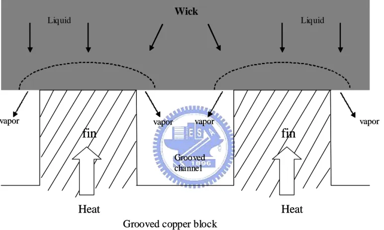
Capillary pumped loop (CPL) is a two-phase thermal management system which circulates the working fluid by the surface tension forces developed in a fine-pore wick. A functional schematic of a CPL is illustrated in Fig. 1.1. It consists of an evaporator, a condenser, a liquid reservoir, and liquid and vapor transport lines. The wick structure is contained in the evaporator. As the heat load is imposed on the evaporator, the liquid in the evaporator vaporizes and moves to the condenser through the vapor line. The condenser condenses the vapor and rejects the heat to the ambient. Then the liquid which is pumped by the capillary force generated by the wick returns to the evaporator. A typical evaporator design is schematically shown in Fig. 1.2. More specifically, the evaporator consists of a grooved copper plate attached on the wick surface, acting as the heating zone, and the vapor can flow in the grooves.
Compared with the conventional heat pipes, CPL has several advantages. In the CPL, the liquid and vapor have different transport lines to avoid the two-phase interaction. Thus the liquid-vapor counter-current flow is avoided and entrainment limit will not occur. Besides, there is no wick structure in the loop except the evaporator. This reduces the pressure drop in the system. According to these reasons, CPL has a higher heat transfer capability and a longer transport distance along with a smaller temperature difference.
1.2 Literature Review
It is well known that CPL was first developed for thermal management in space mission. The initial concept of CPL was proposed at NASA Lewis Research Center by Stenger [1]. But not until the late-1970s serious CPL development for spacecraft
experiments for CPL systems have been performed. In 1993, Ku [2] surveyed capillary pumped loop technology development since the late-1970s. Characterization of CPL and verification of CPL performance were addressed. He also presented some performance anomalies like sudden deprime of evaporators, evaporator deprime during rapid power step down and pressure oscillations during steady operation. Deprime is a CPL failure mode that the vapor or gas appear in the liquid core of the evaporator. The gas interrupts the contact between the liquid and wick. Hence the capillary force does not work.
A CPL would perform its designed functions after it is successfully started. Maidanik et al. [3] investigated the startup period of CPL through experimental and analytical methods. They indicated that the startup can be divided into three stages. In the first stage, the input power is applied to increase the sensible heat of working fluid. As the liquid temperature rises and reaches the required superheat at the onset of nucleate boiling, boiling occurs and the evaporator temperature lowers quickly. This is the second stage. In the third stage the evaporator temperature becomes constant and then the CPL is successfully started. They also found that there is a minimum heat load to ensure a reliable startup. Ku [2], Meyer et al. [4], Hoang and Ku [5], and LaClair and Mudawar [6] also agreed with these findings. Hoang and Ku [5] also discussed the pressure spikes caused by the formation of the bubbles. Sometimes the pressure spike can exceed the capillary limit of the wick. Thus the vapor penetrates the wick into the liquid core. LaClair and Mudawar [6] developed an analytical model to explain the minimum heat load. They indicated that the minimum heat load is required to produce a suitable subcooling in the liquid core so that nucleation can not occur in the liquid core and any bubbles which penetrate the wick can be condensed.
effects on the CPL performance. The causes of pressure and temperature oscillations have been studied theoretically by Hoang and Ku [5, 7]. They believed that the hydrodynamic instability of CPL fluid flow, which was caused by the interaction among the components, led to the oscillation. They also developed a model to predict the oscillation amplitudes. Ku and Hoang [8] showed that the test data were in an excellent agreement with the theoretical model. They also found that the growth and collapse of bubbles was the major reason for the oscillations. Kolos and Herold [9] reached the same conclusion. The experimental results presented by Ku and Hoang [8], O’Connell and Hoang [10] and O’Connell et al. [11] demonstrated that the amplitudes of oscillations could be affected by the properties of components and the operating conditions, such as wick porosity, transport line diameter, input power, and so on.
The operation characteristics of CPL systems subject to various heat loads have been examined in the literature. Ku [2, 12] indicated that the evaporator deprime occurred when the input power was reduced suddenly. Pouzet et al. [13] applied a stepwise heat load to a CPL to study the fundamental response mechanisms. They observed that the system operation would reach a new steady state after certain response time following the change in heat load. Bazzo and Riehl [14] obtained similar test results in a small-scale CPL. The long term heat load profile tests were carried out. They also discussed the effects of different working fluid and noted that a working fluid with a higher latent heat can reduce the startup time and the response time. Besides, a lower superheat in evaporator was also observed.
Since there are no mechanical pumps in CPL systems, the heat transfer performance can be affected by the gravity. Meyer et al. [4] demonstrated the successful CPL operation whether the evaporator was higher or lower than the
known to vary with their height difference. For the evaporator at a higher elevation, Dickey and Peterson [15] and Liao and Zhao [16] showed that the CPL thermal resistance decreased at decreasing height difference. Similarly, Chen and Lin [17] indicated that the CPL thermal resistance decreased at increasing height difference when the condenser is at a higher elevation. They also observed that there is an optimum liquid inventory which led to the minimum thermal resistance.
The heat and mass transfer characteristics in a flat-plate type wick have been examined by several groups. Liao and Zhao [16] studied the effects of wick thickness, particle size and inlet temperature of liquid experimentally. They draw the following conclusions:
1) The heat transfer coefficient increases to a maximum value and then decreases afterward while the imposed heat flux increases.
2) There exists an optimum particle size for maximum heat transfer coefficient. However, the critical heat flux is shown to increase with the decrease of particle size. 3) The critical heat flux increases with a decrease in the thickness, but the thickness does not show noticeable effects on the heat transfer coefficient.
4) Both the heat transfer coefficient and critical heat flux increase with the inlet temperature increase.
They also explored the phase change behavior in the wick experimentally [16, 18, 19]. The process of the two-phase zone growth in the wick has been investigated. When the imposed heat flux was sufficiently high, the vapor film was observed beneath the heated fin.
Some numerical simulations were also conducted to study the flow and heat transfer within the porous structure in the evaporator. Cao and Faghri [20, 21]
contact the heater surface. Thus the wall superheat increases rapidly. A huge amount of vapor generates due to the high wall superheat, causing the pressure increase and finally destroying the liquid-vapor interface. Huang et al. [22] developed a mathematical model to predict the phase change in a porous wick. They showed that instead of an evaporative interface, the phase change occurred in a two phase zone between the vapor zone and the liquid zone in the wick. Hanlon and Ma [23] developed a mathematical model to study the heat transfer capability for a sintered wick structure. Their results showed that the evaporation heat transfer coefficient could be enhanced by reducing the average particle size. They also proposed that thin film evaporation played an important role in the enhancement of evaporating heat transfer. The wick structures discussed above are all considered to be formed from particles of a single pore size. When there existed a pore size distribution, Figus et al. [24] showed that the pore size distribution could restrict the performance.
Several methods have been developed to improve the CPL performance previously. Mo et al. [25, 26] combined the CPL with the electrohydrodynamic technique. They successfully reduce the startup time and show a good enhancement of thermal performance by applying an electric field to the evaporator wick. Besides, the depriming phenomenon can also be prevented. Muraoka et al. [27] used a porous structure inside the condenser to stabilize the interface between the liquid and vapor phases. In order to prevent the gas accumulation in the liquid core, Hoang [28, 29] proposed a new design concept. A minor loop is used to remove the gas in the liquid core. The test results show that the deprime can be successfully prevented.
As the CPL technology was first developed for spacecraft applications, the dimensions of the systems are in the order of meters. The large scale CPL systems have been extensively studied before. In order to apply the CPL technology to
[30] reported that small evaporators tend to deprime more easily probably due to an insufficient subcooled liquid supply to the porous wick. Bazzo and Riehl [14] examined the operation characteristics of a small-scale CPL system. The similarity between the large and small scale systems was verified. Most of the CPL evaporators discussed above are designed with a cylindrical evaporator. For the practical utility in electronics cooling, a flat shape evaporator is proposed [17, 31]. Some important characteristics and results of the previous works for CPL reviewed above are listed in Table 1.1.
Heat spreader is often used as a heat sink in electronics cooling to reduce the thermal resistance of the heat sink by increasing the heat exchange area with the coolant. Feng and Xu[32] showed that the spreading resistance was affected by the thickness of the spreader, the ratio of heating area and spreading area, and the location of the heater. Maranzana et al. [33] proposed a method to determine the optimal thickness for the minimum spreading resistance.
1.3 Objective
Over the past, the large scale CPL systems have been successfully used for spacecraft applications. But the characteristics of the small scale CPL systems for electronics cooling are less explored. In the present study, an experimental capillary pumped loop system for electronics cooling will be established to test its performance. Methods to improve the thermal performance of the loop will be investigated in this study. The performance difference between using the plane fins and pin fins to form the grooved channels will be examined at first. Besides, the possible heat transfer augmentation in the evaporator section through the use of heat spreader attached to
surfaces, which in turn greatly increases the surface area for the liquid vaporization, will be tested.
Table 1.1 Summary of results in previous CPL studies
Authors Qe,max (W)
q"e,max (W/㎝ 2
) T evap,max(℃) Rth,min (K/W) Hg (cm) wick properties working fluid Applications notation
Maidanik et al.
(1993) 775 3.5 32 0
pore radius 1.3μm,
polyethylene ammonia Spacecraft
Meyer et al. (1993) 1129 7.9 90 0.0125 -200 pore size 1.5 μm , porosity 70% , sintered nickel ammonia spacecraft Ku and Hoang (1995) 700 1.8 40 0.077 0 permeability , 4.43*10^-13 ㎡ ammonia spacecraft O'Connell and Hoang (1996) 500 1.27 30 0 pore radius 19.08 , 16.12 , 13.02 , 8.3μm ammonia spacecraft O'Connell and Ku (1996) 500 1.27 30 0 pore radius 16.12 , 13.02 μm ammonia spacecraft Pouzet et al. (2004) 600 5 33 0.058 0 pore radius 20 μm,
polyethylene R-134A spacecraft
Mo et al.
(1999) 50 0.25 26.5 0.04 0
pore radius 1.5μm,
polyethylene R-134A spacecraft
Table 1.1 Continued (1)
Authors Qe,max (W)
q"e,max (W/㎝ 2
) T evap,max(℃) Rth,min (K/W) Hg (cm) wick properties working fluid Applications notation
Mo et al. (2000) 650 3.21 26 0.004 0pore radius 1.5μm,
polyethylene R-134A spacecraft
Bazzo and Riehl
(2003) 50 2.09 40 0.6 0 pore radius 20μm , porosity 60% , permeability 10^-12 ㎡ , polyethylene acetone electronics cooling Bazzo and Riehl
(2003) 50 2.09 30 0.34 0 pore radius 20μm , porosity 60% , permeability 10^-12 ㎡ , polyethylene ammonia electronics cooling Dickey and Peterson (1994) 130 2.87 58 0.15 0
sintered nickel, pore radius
1~1.5μm, porosity 70% ammonia
electronics cooling Chen and Lin
(2001) 40 2.5 83 1.28 12 pore radius 10.5 μm , permeability 6*10^-13 ㎡ , polyethylene FC-72 electronics cooling 10
Table 1.1 Continued (2)
Authors Qe,max (W)
q"e,max (W/㎝ 2
) T evap,max(℃) Rth,min (K/W) Hg (cm) wick properties
working
fluid Applications notation
Liao and Zhao
(1999) 887 32 168 0.048 -0.5 partical diameters 0.55, 1.09, 1.99, 2.56 mm, packed glass beads water electronics cooling only evaporator Liao and Zhao
(2000) 256 32 144.6 0.104 1partical diameters 1.99 mm,
packed glass beads water
electronics cooling
only evaporator Zhao and Liao
(2000) 740 25.9 135 0.032 -3.5
partical diameters 1.09 mm,
packed glass beads water
electronics cooling
only evaporator
12
Liquid
Grooved channel
Grooved copper block
Wick
vapor vapor vapor vaporfin
fin
LiquidHeat
Heat
Liquid Grooved channelGrooved copper block
Wick
vapor vapor vapor vaporfin
fin
LiquidHeat
Heat
13CHAPTER 2
EXPERIMENTAL APPARATUS AND PROCEDURES
In the present study, the experimental system established to test an improved design of a CPL is schematically shown in Figure 2.1. The experimental system consists of four major parts, namely, a test CPL loop, a fluid inventory unit, a cold-water loop and a measurement unit. These parts are described in the following.
2.1 CPL Test Loop
The present test CPL loop includes an evaporator, a condenser, and vapor and liquid transport lines and it is shown in Figure 2.2 by a three-dimensional plot. The details of the dimensions and materials used for various components in the loop are given in Table 2.1. Note that here the evaporator and condenser are plotted at the same height and the gravity effects do not exist. But in the actual test we can vary the relative height of the evaporator and condenser.
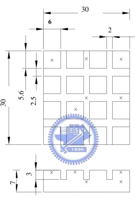
Plots showing the detailed structure of the evaporator are given in Figure 2.3. Typically, the evaporator consists of a wick structure, a heater and a grooved block. Instead of the grooved channels formed by the parallel plane fins adopted in the previous study [34], the vapor channels formed by the parallel square pin fins are tested here. Two types of pin fins of different sizes are chosen, as schematically shown in Figures 2.4 and 2.5. The type-1 pin fins are much smaller and more space is available for the liquid vaporization to take place. The dimensions of the pin fins are given in Figures 2.4 and 2.5. Besides, a heat spreader with grooved channels made from a copper plate of 10-mm thick will be tested in this investigation. The grooved vapor channels formed by parallel plane fins on a copper plate with a much larger
surface area than the directly heated copper block, the so called heat spreader, are schematically shown in Figure 2.6. Moreover, the grooved channels with rough vertical and bottom surfaces are also tested. The surface roughness is produced from the sand blasting process, which uses tiny particles to directly hit the surfaces. Specifically, the Al2O3particles of 120μm in mean diameter are used here. The photo of the rough surface is shown in Figure 2.7. Two resistance heaters are inserted into the 30mm×30mm heated copper block to simulate a heat dissipating CPU and the heaters are covered with thermal grease to reduce the thermal contact resistance. The wick used in present study is made from open-cell blowing foam of polyvinyl alcohol (PVA), and the structure of this PVA is illustrated by the photos given in Figure 2.8 (its mean pore radius is 21μm, porosity 65%, and permeability ) and the
wick layer is and 57
11 2 3.0 10× − m mm
mm
mm 30 3
30 × × mm×57mm×6mm in size. The outside
surfaces of the heated copper block, grooved copper block and wick are all thermally insulated by teflon wraps. They are then installed in a cylindrical teflon base. In order to further reduce heat loss, the outside surface of the whole evaporator is covered with a superlon insulation layer of 8-mm in thickness. An observational window is also opened in the teflon cover to facilitate the visualization of the flow in the grooved vapor channels. The evaporator is connected with the condenser through the liquid and vapor transport lines.
In designing the condenser, the heat transfer area and the cooling mechanisms to cool down the working fluid need to be considered. Specifically, the condenser must have the following characteristics:
1) Small temperature difference between the condenser and heat sink. 2) Small flow resistance inside the condenser.
5) Easy fabrication and low cost.
Herein, we chose a double-tube heat exchanger as the condenser. Cold water is used to condense the vapor and to control the temperature of the condenser.
The transport lines include the vapor line and liquid line. In normal operation the vapor from the evaporator flows through the vapor line and enters the condenser and the liquid from the condenser flows to the evaporator through the liquid line. In order to reduce the friction loss, smooth teflon tubes with inner diameter of 4.5 mm are chosen for the vapor line and liquid line.
2.2 Fluid Inventory Unit
Before the working fluid is input to the CPL, it is important to insure that the system is in a vacuum condition and no noncondensible gas exists in the CPL. The working fluid inventory unit includes a working fluid tank, a dispensing burette, and a vacuum pump, which connects with the CPL loop through tubes and valves.
To maximize the capillary limit and heat transport of the CPL, the working fluid should have the following properties:
1) large surface tension 2) high density
3) large latent heat 4) low viscosity
In this study deionized water is chosen as the working fluid.
2.3 Cold-Water Loop
The cold-water loop is designed for condensing the water vapor from the evaporator. Using a cold-water thermostat and a spherical valve, we can adjust the
allows us to control the temperature of the condenser.
2.4 Measurement Unit
T-type (copper-constantan) thermocouples are used to measure the temperatures at selected locations in the test CPL loop. Specifically, six calibrated thermocouples are employed to measure the temperature of the copper blocks with pin fins and plane fins on it. The locations of the thermocouples in the block are schematically shown in Figures 2.4 and 2.5. To estimate the heat loss from the evaporator, the temperature of the outer surface of the adiabatic cotton is also measured, as schematically shown in Figure 2.9. Besides, the temperature of the working fluid at the inlets and exits of the evaporator and condenser shown in Figure 2.2 are measured.
Four pressure sensors (YOKOGAWA FP101A) are used to measure the pressure at the inlets and exits of the evaporator and condenser. The accuracy of the pressure measurement is ±0.25% for the measured range of 0~200 kPa
2.5 Equipments
1) DC Power Supply:
A DC power supply of 60V and 3A is selected to supply the required electric current to the heaters in the evaporator section. The DC current through the heaters is measured by a Yokogawa DC meter with an accuracy of . Then the voltage drop across the heater is measured by a Yokogawa multimeter. Thus the power input to the heater can be calculated. % 2 . 0 ± 2) Data Acquisition:
connected to a personal computer. The voltage signals from the thermocouples are converted into the temperature by the internal calibration equations in the computer and are displayed on the screen simultaneously.
3) Thermostat:
The maximum cooling capacity of the thermostat is 1,200 W with a maximum water volume flow rate of 5 L /min
4) Vacuum Pump:
An oil rotary vacuum pump (VLVAC G-100D) with an ultimate pressure of torr and a pumping speed of 120 L/min is used here
4 10 5× −
2.6 Experimental Procedures
Before each experiment, the vacuum pump is connected with the CPL to get rid of the non-condensable gas possibly existing in the CPL loop. Then the working fluid is injected into the CPL from the fluid inventory unit. Besides, the thermostat of the cold-water loop is set at a predetermined level and the DC power supply is turned on to input the preset amount of heat to the evaporator. After the system reaches a statistically stable state, the temperature and pressure data from various transducers are recorded and processed by the data acquisition unit.
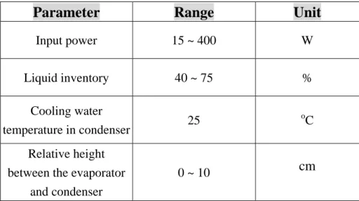
2.7 Experimental Parameters
In the present study the experimental parameters include the input power to the evaporator, the liquid inventory in the loop, and the elevation difference between the condenser and evaporator. The ranges of the experimental parameters to be investigated are listed in Table 2.2.
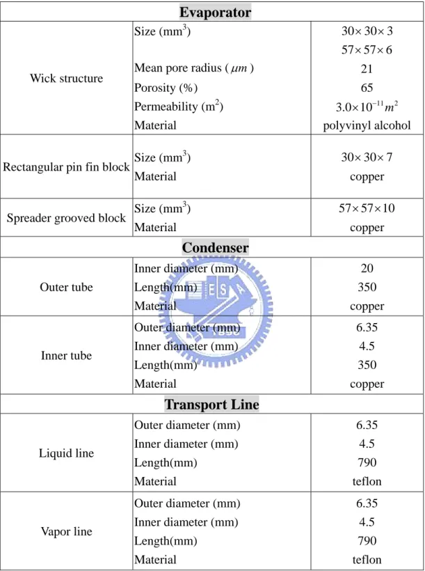
Table 2.1 Geometric and material characteristics of the present CPL system
.
Evaporator
Wick structure
Size (mm3)
Mean pore radius (µ ) m Porosity (%) Permeability (m2) Material 3 30 30× × 57 57 6× × 21 65 11 2 3.0 10× − m polyvinyl alcohol
Rectangular pin fin block Size (mm
3 ) Material 7 30 30× × copper
Spreader grooved block Size (mm
3 ) Material 57 57 10× × copper
Condenser
Outer tube Inner diameter (mm) Length(mm) Material 20 350 copper Inner tube Outer diameter (mm) Inner diameter (mm) Length(mm) Material 6.35 4.5 350 copperTransport Line
Liquid line Outer diameter (mm) Inner diameter (mm) Length(mm) Material 6.35 4.5 790 teflon Vapor line Outer diameter (mm) Inner diameter (mm) Length(mm) Material 6.35 4.5 790 teflonTable 2.2 Experimental parameters
Parameter
Range
Unit
Input power 15 ~ 400 W Liquid inventory 40 ~ 75 % Cooling water temperature in condenser 25 o C Relative height
between the evaporator and condenser
TANK VALVE DISPENSING BURETTE DC POWER SUPPER VACUUM PUMP FLOWMETER COLD-WATER THERMOSTAT CONDENSER VAPOR LINE LIQUID LINE T T T T T T T T T T T P P 21 P P EVAPORATOR
Cooling Water Out PCond. Inlet
Liquid Line
Flow Cooling Water InCondenser
TCond. InletVapor Line
FlowEvaporator
TEvap. Outlet TEvap. Inlet TCond. Outlet Thermocouples PCond. Outlet PEvap. Inlet 22 PEvap. Outlet Pressure sensorVapor
Liquid
Acrylic
Teflon cover
Window
Wick structure
Rectangular pin
fin block
Resistance
heaters
Heated copper
block
Teflon base
30
3
2.4
3
30
2.4
7
3
Unit : mm
Locations of
thermocouples
30
6
2
5.6
2.5
30
3
7
Locations of
thermocouples
Unit : mm
57
57
2.4
3
10
Locations of
Unit : mm
thermocouples
1mm
80μm
28
Thermocouples
Adiabatic
cotton
T
o,b1T
o,b2T
o,b3T
o,r1T
o,r2T
o,r3T
o,r6T
o,r5T
o,r4Teflon heater base Teflon cover Acrylic cover
T
o,t3T
o,t2T
o,t1Liquid
Resistance heaters 2 9CHAPTER 3
DATA REDUCTION AND SIMPLE ANALYSIS
In the present test of an improved CPL system design, a data reduction analysis is needed to calculate the system thermal resistance from the measured raw data. On the other hand, the thermodynamic states, heat transfer limitation and pressure drop in the CPL loop are discussed in the following.
3.1 Data Reduction
Conventionally, the concept of the thermal resistance is adopted to represent the CPL performance. It shows the heat removal capacity of a CPL. The thermal resistance is usually defined as
evap cond th e T T R Q − = . (3.1)
where is the mean measured temperature at the selected locations of the grooved block in the evaporator, is the mean temperature of the working fluid in the condenser, and is the effective power input to the CPL. The total power input and the effective power input are respectively evaluated from the equations: evap T cond T e Q t Q Qe I V Qt = ⋅ . (3.2) where V and I are individually the voltage drop across and electric current through the resistance heaters, and
e t lo
Q =Q Q− ss (3.3) Here the heat loss from the evaporator Qloss is approximately estimated from
the relation
, , , , ,
, ( ) ( ) (
loss nt t o t amb n r r o r amb n b b o b amb
Q =h A T −T +h A T −T +h A T −T ) (3.4) indicating that the natural convection heat transfer from the outside surfaces of the evaporator to the ambient includes three major parts, namely, from the top, circumferential and bottom surfaces of the evaporator to the ambient. The associated natural convection heat transfer coefficients can be approximately evaluated from the empirical correlations [35] as
(
)
0.25 , , 1.32 o t amb n t T T h d ⎡ − ⎤ ⎢ = ⎢ ⎥ ⎣ ⎦ ⎥ . (3.5)(
)
0.25 , , 1.42 o r amb n r T T h d ⎡ − ⎤ ⎢ = ⎢ ⎥ ⎣ ⎦ ⎥ (3.6)(
)
0.25 , , 0.59 o b amb n b T T h d ⎡ − ⎤ ⎢ = ⎢ ⎥ ⎣ ⎦ ⎥ . (3.7)where hn is the natural convection heat transfer coefficient from the outside surface of
the superlon insulation layer to the ambient, A is the outside surface area of the superlon insulation layer, To is the average temperature of the outer surface of the superlon insulation layer, Tamb is the ambient temperature, and d is the diameter of the
evaporator. The relative heat loss from the evaporator is defined as
(
)
% 100 × − = t e t Q Q Q ε (3.6)From the thermocouple data measured at the outside surface of the adiabatic cotton covering the evaporator, the heat loss from the evaporator to the ambient is estimated. The results from this estimation show that the heat losses for all cases investigated here are all less than 3.0 %.
3.2 Thermodynamic States and Heat Transfer Limitation
As discussed in chapter 1, CPL is a two-phase liquid-vapor heat transport device consisting of an evaporator containing a wick structure, a condenser, a reservoir, and distinct liquid and vapor lines. There is no reservoir element in the present study. Figure 3.1(a) schematically shows a typical CPL system without reservoir. The corresponding thermodynamic states of the working fluid at various locations of the CPL are indicated in Fig. 3.1(b). At location 1 (the wick-copper block contacted heating zone), liquid vaporizes at the saturation state and the vapor moves through the grooves, resulting in some pressure loss and the vapor becomes superheated at location 2. The vapor finally flows into the vapor line. Some pressure loss also results in the vapor line as the vapor moves through it and the vapor is still superheated at location 3. After entering the condenser, the vapor condensation occurs. Thus we have two-phase liquid-vapor mixture at locations 4 and 5. Beyond location 5, all vapor is condensed and the working fluid is in liquid state. The working fluid continues to cool down in the condenser and reaches a subcooled temperature at the condenser exit at location 7. The liquid flows back to the evaporator through the liquid line, accompanying with some pressure loss. At the inlet of the evaporator (location 8) the liquid is subcooled. As the liquid moves into the wick, it gets heated. Boiling and evaporation take place near the wick- copper block contacted region at location 9. This completes the thermodynamic cycle for the CPL.
The heat transfer limits of a CPL are similar to that of heat pipe. The major heat transport limits for a CPL are:
1) Capillary limit:
In a normal CPL operation, the wick structure should produce sufficient capillary force to drive the vapor and liquid flows. For a raise in the heat input to the evaporator, the liquid and vapor flows speed up, leading to an increase in the flow
resistance as the menisci form at the liquid/vapor interface. This means that the capillary force should be high enough to circulate the flow of the working fluid along the loop. When the radii of curvature for the menisci get larger at a higher heat input so that they are equal to the capillary radius, the capillary pressure reaches a maximum level, resulting the so called “capillary limit”.
2) Boiling limit:
As the heat input to the evaporator exceeds certain value, boiling of liquid begins and vapor bubbles start to appear inside the wick structure. At a relatively high heat input bubbles are generated at a large size and at a vary high rate. The bubbles would block the wick structure and form a layer of vapor film in the contact zone. Therefore, the resulting thermal resistance becomes very large and heat transfer capability of the CPL deteriorates. This is designated as the “boiling limit”.
3) Sonic limit:
The vapor mass flux is known to increase with the magnitude of the heat input. As the vapor speed arrives at the sonic point, the flow in the CPL will be choked, resulting the “sonic limit”.
3.3 System Pressure Drop Analysis
In view of the presence of the capillary limit, the maximum capillary pressure generated in the wick should be greater than or equal to the overall loop pressure drop for a CPL to function well. Hence,
,max
cap v l vg w g
P P P P P
∆ ≥ ∆ + ∆ + ∆ + ∆ + ∆P (3.7) here ∆Pcap,maxis the maximum capillary pressure, ∆ the total pressure drop in the Pv
the wick structure, and the pressure drop due to the gravity. These terms are described in the following.
g
P
∆
3.3.1 Maximum capillary pressure
In a steady CPL operation, the capillary pressure can be calculated from the contacted angle of vapor-liquid interface θ, working fluid surface tension σ and effective capillary radius . When the contact angle is equal to zero, we obtain a maximum capillary pressure. In that case, the curvature radius of the vapor-liquid interface is equal to the effective capillary radius. Specifically,
c r c cap r P = 2σcosθ ∆ (3.8) When θ =0, c cap r P ,max = 2σ ∆ (3.9)
3.3.2 Pressure drops in transport lines
The transport lines include the vapor line and liquid line. Note that in the transport lines the fluid flow in the tubes is assumed to be fully-developed. The total pressure drop in the tube due to the friction, the so called “major losses”, can be evaluated from the relation
2 2 V D L f Pmajor = ρ ∆ (3.10)
where f is the friction factor, L is the flow length, D is the tube diameter, ρ is the density of working fluid, V is the average speed of the working fluid.
If the flow is laminar and fully–developed for the Reynolds number 2300, the friction factor can be expressed in a simple relation as
≤
Re 64 =
f . (3.11) For 2300 < Re <10,000 the friction factor can be approximately evaluated from the Gnielinski correlation [36] as
(
)
2 101.82 log Re 1.64
f = − − . (3.12) For Re > 10,000 the flow can be considered as turbulent. When the tube is smooth and the flow is turbulent, the friction factor can be approximately evaluated from the Blasius correlation [37] as
4 1 Re 316 . 0 = f (3.13)
3.3.3 Pressure drop in grooved channels
The pressure drop resulting from the vapor passing through grooved channels of the evaporator can be estimated as
2 2 vg h L V P f D ρ ∆ = (3.14)
where L is the grooved channel length and Dh is the hydraulic diameter of each grooved
channel.
3.3.4 Pressure drop in wick structure
According to the Darcy’s law for a low speed single-phase liquid flow moving in a porous medium and assuming the flow being one-dimensional in z-direction and laminar, the flow speed can be approximated as
⎟ ⎠ ⎞ ⎜ ⎝ ⎛ ∂ ∂ − = z p K V l w z µ (3.15)
From the Conservation of Mass, we also have
z l c m V A ρ =
.
. ..(3.16) Combining the above two equations givesl w l c w m P A K µ ρ ∆ = l (3.17)
.
3.3.5 Pressure drop due to gravity
If there is a relative height between the evaporator and condenser, the gravitational head should be considered. It can be calculated from the relation
gh Pg =ρl
∆ (3.18) where g is the gravitational acceleration, h is the difference in the heights of the evaporator and condenser.
3.4 Estimate of Mass Flow Rate
In a steady CPL operation, the energy balance for the evaporator can be expressed as fg P e h C Q =Q +Q ∆T fg ≈ = (3.19) Assuming the sensible energy transfer is small compared with the latent energy transfer, the above equation can be written as
fg
e h
Q Q m h
.
(3.20) thus the mass flow rate of the working flow in the CPL can be calculated from the relation m.
= e fg Q (3.21) hhere Qe is the effective power input to the CPL, m
.
is the mass flow rate, and hfg isthe latent heat of evaporation. Using this estimated mass flow rate in the above equations for the pressure drop analysis we can evaluate the pressure drops in each section of the CPL.
3.5 Uncertainty Analysis
proposed by Kline and McClintock [38]. The detailed results from this uncertainty analysis are summarized in Table 3.1.
Table 3.1 Summary of the uncertainty analysis
Parameter
Uncertainty
Length of grooved copper block (m) Width of grooved copper block (m) Thickness of grooved copper block (m) Dimensions of grooved channel (m)
±0.0005 ±0.0005 ±0.0005 ±0.00005 Temperature, T ( )℃ Temperature difference, ∆T (℃) ±0.2 ±0.28 Current, I (%) Voltage, V (%)
Total heat load, Qt (%)
Heat loss, Qloss (%)
Thermal resistance, R (%) ±0.206 ±0.05 ±0.212 ±10.2 ±11.1
Condenser 3. 4. 5. 6. 7. Liquid line Vapor line Wick 8. 9. 2. 1. Evaporator
Saturation
Line
Heat(a)
1. 2. 3. 4. 5. 6. 7. 8. 9. P1 P2 P4 PRESSURE P8 P9 TEMPERATURE T8 T5 T4 T1 T2(b)
CHAPTER 4
RESULTS AND DISCUSSION
This chapter presents the experimental data obtained in the present investigation of an improved CPL system. The effects of the liquid inventory and the relative height between the evaporator and condenser on the heat transfer performances of the CPL with three different improved designs are examined. The liquid inventory is defined as the ratio of the total volume of working fluid in the loop to the total loop volume available for the working fluid. Table 4.1 gives the volume of each component in the CPL system available for the working fluid to pass through. The results obtained here for the grooved channels formed by the square pin fins are compared with those for the grooved channels formed by the plane fins measured in the previous study [34]. Besides, the effects of using the heat spreader and roughing the vertical and bottom surfaces of the grooved channels on the CPL performance will be examined.
In the experiment, the mean evaporator temperature (Tevap) and condenser
temperature (Tcond ), which are the average temperatures measured at selected
locations in the block containing the grooved channels and the condenser (double-tube heat exchanger), and the temperatures of the working fluid measured at the inlets and exits of the evaporator and condenser shown in Figures 2.2, 2.4 and 2.5 will be inspected. It should be mentioned that the experimental test of the present CPL system will be terminated as the mean evaporator temperature exceeds 80℃.
4.1 Performance Comparison between Vapor Channels Formed by Pin Fins and Plane Fins
and plane fins, the relative height between the evaporator and condenser is first fixed at 0 cm, and the liquid inventory is at 62%. Figure 4.1 shows the results from this test. It is first noted that the maximum heat transfer performance of the type-2 pin fin block is about 120W before Tevap exceeds 80℃ and it is lower than that for the
type-1 pin fin block and grooved block. This clearly indicates that using the pin fins to form the vapor channels in the copper block is less effective in vapor transport than the grooved channels. This result, in turn, is the consequence of the vapor flows in various parts of channels formed by the pin fins being normal to each other, causing a mutual retarding of the vapor to move slower into the vapor transport line. It was further noted in the test that the amplitude of the temperature oscillation in the evaporator for the pin fin blocks is about 1℃.
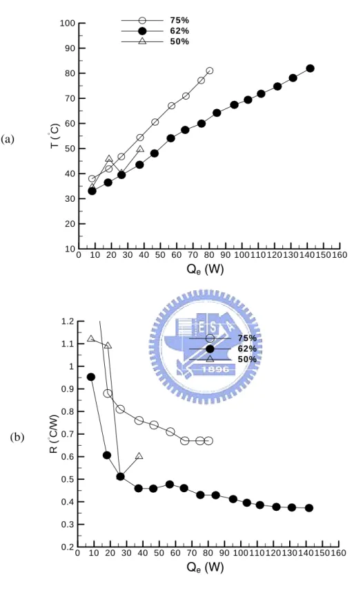
Then, comparison is made for different liquid inventories with the relative height between the evaporator and condenser fixed at 0 cm. The liquid inventory is varied from 50% to 75%. The test is conducted for the type-1 pin fin block and the results are shown in Figure 4.2. These results are compared with that for the grooved block in Figures 4.3 - 4.5. Note from the results in Figure 4.2 for the type-1 pin fin block that at the liquid inventory of 62% the CPL has the highest heat transfer capability Qe,max of 141W. For the other two liquid inventories Qe,max is much lower
especially for the liquid inventory of 57%. The results in Figures 4.3 - 4.5 indicate that only at the liquid inventory of 75% the CPL heat transfer performance for the type-1 pin fin block is better than the grooved block.
Finally, the effects of the relative height between the evaporator and condenser on the CPL performance with the pin fin and plane fin blocks are tested. Here we only test the type-1 pin fin block with the liquid inventory fixed at 62%. The relative height