Research Article
Investigation of Liquid Crystal Ripple Using Ericksen-Leslie
Theory for Displays Subject to Tactile Force
Y. J. Lee,
1T. S. Liu,
1Mao-Hsing Lin,
2and Kun-Feng Huang
21Department of Mechanical Engineering, National Chiao Tung University, Hsinchu 30010, Taiwan 2Innolux Corporation, Tainan 74147, Taiwan
Correspondence should be addressed to T. S. Liu; [email protected] Received 25 June 2013; Accepted 7 December 2013
Academic Editor: Farzad Khani
Copyright © 2013 Y. J. Lee et al. This is an open access article distributed under the Creative Commons Attribution License, which permits unrestricted use, distribution, and reproduction in any medium, provided the original work is properly cited.
Liquid crystal display panels subjected to tactile force will show ripple propagation on screens. Tactile forces change tilt angles of liquid crystal molecules and alter optical transmission so as to generate ripple on screens. Based on the Ericksen-Leslie theory, this study investigates ripple propagation by dealing with tilt angles of liquid crystal molecules. Tactile force effects are taken into account to derive the molecule equation of motion for liquid crystals. Analytical results show that viscosity, tactile force, the thickness of cell gap, and Leslie viscosity coefficient lead to tilt angle variation. Tilt angle variations of PAA liquid crystal molecules are sensitive to tactile force magnitudes, while those of 5CB and MBBA with larger viscosity are not. Analytical derivation is validated by numerical results.
1. Introduction
Many physical phenomena exhibited by the nematic phase liquid crystals (LC), such as unusual flow properties or the LC response to electric and magnetic fields, can be studied by treating LC as a continuous medium. Ericksen and Leslie
[1–3] formulated general conservation laws and constitutive
equations describing the dynamic behavior. Other contin-uum theories have been proposed, but it turns out that the Ericksen-Leslie theory is the one that is most widely used in discussing the nematic state. Based on the continuum theory of Ericksen-Leslie, this study constructs a theoretical model in order to investigate the tilt angle variation of LC subjected to both electric field and tactile force. The continuum theory for the nematic state flow is established in two dynamical equations—conservation laws and constitutive equations. Both equations are coupled with each other due to the properties of flow and the director of liquid crystal molecules.
Brochard et al. [4] investigated transient distortions in
a nematic film by increasing or decreasing of the magnetic
field. Lei et al. [5] used the Ericksen-Leslie equation to
describe soliton propagation in nematic liquid crystals under
shear. Leslie [6] presented a concise but clear derivation
of continuum equations commonly employed to describe
static and dynamic phenomena in nematic liquid crystals.
Gleeson et al. [7] proposed a two-dimensional theory in
which the excitations are fronts between distinct solutions of the steady-state Ericksen-Leslie equations. Lin and Liu
[8] use the Ericksen-Leslie equation to describe the flow
of liquid crystal material and prove the global existence of
weak solutions. De Andrade Lima and Rey [9] proposed
computational modeling of the steady capillary Poiseuille flow of flow-aligning discotic nematic liquid crystals; using the Ericksen-Leslie equations predicts solution multiplicity
and multistability. Nie et al. [10] used a cell gap and surface
dynamic method to derive analytical expressions of LC response time under finite anchoring energy conditions. Cruz
et al. [11] used a finite difference technique, based on a
projec-tion method, which is developed for solving the dynamic three-dimensional Ericksen-Leslie equations for liquid crys-tals subject to a strong magnetic field.
Liquid crystal display panels subjected to tactile force will show ripple propagation on screens. Tactile forces change tilt angles of liquid crystal molecules and alter optical transmission so as to generate ripple on screens. Based on the Ericksen-Leslie theory, this paper aims to develop LC dynamics subject to tactile force. Tactile force effects are taken into account to derive the molecule director equation
z F x 𝜙 𝜃 + + + + + + + + + + + ̂n z = 0
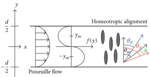
Figure 1: Homeotropic alignment LC layer sandwiched between parallel substrates, where𝑧 = 0 and 𝑧 = 𝑑 are the bottom and top substrates, respectively. Poiseuille flow Homeotropic alignment x d 2 −d 2 −ym ym f(y) 𝜃E 𝜃F 𝜃m 𝜙 y
Figure 2: Directors of LC molecules with homeotropic alignment are changed by Poiseuille flow.
of motion for liquid crystals. A theoretical model is thus proposed to analyze the tilt angle of nematic liquid crystals subject to tactile forces.
2. Derivation of Ericksen-Leslie Theory
2.1. One-Dimensional Model. Figure 1shows a homeotropic
alignment liquid crystal layer sandwiched between parallel
substrates, where𝑧 = 0 and 𝑧 = 𝑑 stand for the bottom
and top substrates, respectively [12]. The thickness between
bottom and top substrates is𝑑. The 𝑧-axis is normal to the
plane of the substrates, and the electric field𝐸 = 8.9 V is along
the𝑧-axis. 𝜃 denotes a tilt angle caused by a tactile force and 𝜙
is the tilt angle defined as the angle between the𝑧-axis and LC
directors. The dynamics of director-axis rotation is described
by an Ericksen-Leslie equation [13,14]: 𝜕 𝜕𝑧[(𝐾11cos2𝜃 + 𝐾33sin2𝜃) 𝜕𝜃 𝜕𝑧] + (𝐾33− 𝐾11) sin 𝜃 cos 𝜃(𝜕𝜃𝜕𝑧)2 + (𝛼2sin2𝜃 − 𝛼3cos2𝜃)𝜕𝑧𝜕V + 𝜀0𝜀𝑎𝐸2sin𝜃 cos 𝜃 = 𝛾𝜕𝜃 𝜕𝑡 + 𝑀 𝜕2𝜃 𝜕𝑡2, (1) 0 1 2 3 4 0 0.02 0.04 0.06 0.08 0.1 T il t a n gle (deg) Cell gap (𝜇m) 1 dyne 0.5 dyne 0.1 dyne (a) 0 1 2 3 4 5 6 0 0.02 0.04 0.06 0.08 0.1 T il t a n gle (deg) Cell gap (𝜇m) 1 dyne 0.5 dyne 0.1 dyne (b)
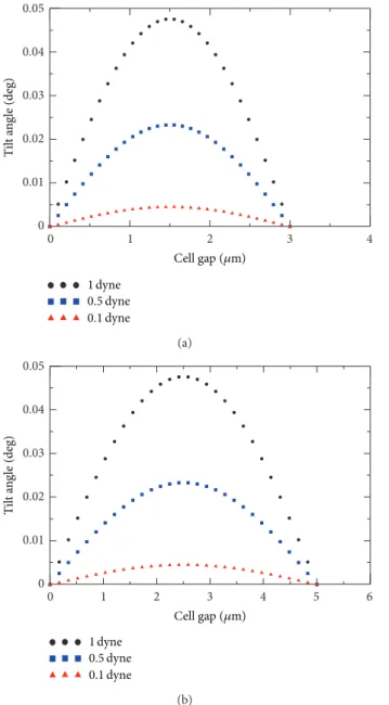
Figure 3: Comparison of molecule tilt angles between cell gap thicknesses of (a) 3𝜇m and (b) 5 𝜇m when a tactile force is applied to LCD screen with 5CB liquid crystals.
0 1 2 3 4 0 0.01 0.02 0.03 0.04 T il t a n gle (deg) Cell gap (𝜇m) 1 dyne 0.5 dyne 0.1 dyne (a) 0 1 2 3 4 5 6 0 0.01 0.02 0.03 0.04 0.05 T il t a n gle (deg) Cell gap (𝜇m) 1 dyne 0.5 dyne 0.1 dyne (b)
Figure 4: Comparison of molecule tilt angles between cell gap thicknesses of (a) 3𝜇m and (b) 5 𝜇m when a tactile force is applied to LCD screen with MBBA liquid crystals.
where𝐾11,𝐾22, and𝐾33are elastic constants,𝛼2and𝛼3are
Leslie viscosities,V is the flow velocity, 𝛾 = 𝛼3 − 𝛼2 is the
rotational viscosity, and𝑀 is the inertia of LC directors. If
backflows, inertial effects, and electric field energy densities
are ignored, (1) is reduced to
𝛾𝜕𝜃
𝜕𝑡 = 𝐾
𝜕2𝜃
𝜕𝑧2 + 𝐹 × ̂𝑛, (2)
where𝐹 is the tactile force, 𝐾 is the one-constant
approx-imation with 𝐾 = 𝐾11 = 𝐾22 = 𝐾33, and ̂𝑛 is the LC
director. Equation (2) is a torque balance equation relating
the viscosity, the elasticity, and the torque due to tactile force.
A cross product𝐹 × ̂𝑛 represents a torque expressed by
𝐹 × ̂𝑛 = |𝐹| |𝑛| sin (𝜃 − 𝜙) , (3) 0 1 2 3 4 0 0.4 0.8 1.2 T il t a n gle (deg) Cell gap (𝜇m) 1 dyne 0.5 dyne 0.1 dyne (a) 0 1 2 3 4 5 6 0 0.4 0.8 1.2 1.6 T il t a n gle (deg) Cell gap (𝜇m) 1 dyne 0.5 dyne 0.1 dyne (b)
Figure 5: Comparison of molecule tilt angles among cell gap thicknesses of (a) 3𝜇m and (b) 5 𝜇m when a tactile force is applied to LCD screen with PAA liquid crystals.
where|𝑛| = 1. Substituting (3) into (2) gives
𝛾𝜕𝜃
𝜕𝑡 = 𝐾
𝜕2𝜃
𝜕𝑧2 + 𝐹 sin (𝜃 − 𝜙) . (4)
Liquid crystal dynamics is described in this study by consid-ering the following two cases.
Case 1. When torque due to tactile force is much larger than elastic torque,
𝐹sin(𝜃 − 𝜙) ≫𝐾𝜕𝜕𝑧2𝜃2
0 1 2 3 4 0 0.01 0.02 0.03 T il t a n gle (deg) Cell gap (𝜇m) 1 dyne 0.5 dyne 0.1 dyne (a) 0 1 2 3 4 0 0.01 0.02 T il t a n gle (deg) Cell gap (𝜇m) 1 dyne 0.5 dyne 0.1 dyne (b) 0 1 2 3 4 0 0.1 0.2 0.3 0.4 0.5 0.6 T il t a n gle (deg) Cell gap (𝜇m) 1 dyne 0.5 dyne 0.1 dyne (c)
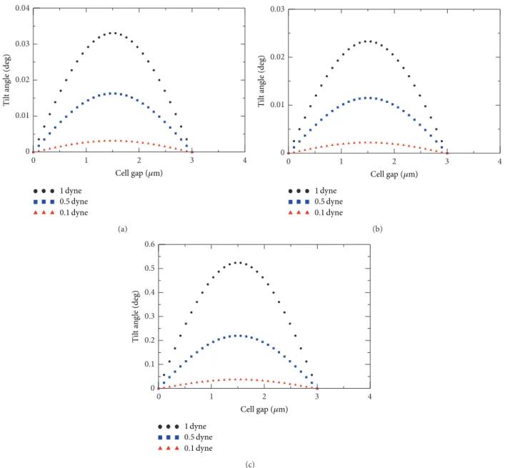
Figure 6: Comparison of molecule tilt angles with different LC materials (a) 5CB, (b) MBBA, and (c) PAA when a tactile force is applied to LCD screen.
However, when the tilt angle is small, sin𝜃 ≈ 𝜃 and cos 𝜃 ≈ 1
and (4) becomes
𝛾𝜕𝜃𝜕𝑡 = 𝐹 ⋅ (cos 𝜙) ⋅ 𝜃 − 𝐹 ⋅ sin 𝜙. (6)
Case 2. When torque due to tactile force is much smaller than elastic torque,
𝐹sin(𝜃 − 𝜙) ≪𝐾𝜕𝜕𝑧2𝜃2
. (7)
Equation (4) thus becomes
𝛾𝜕𝜃𝜕𝑡 = 𝐾𝜕𝜕𝑧2𝜃2. (8)
Based on separation of variables, assume 𝜃(𝑡, 𝑧) =
𝜃(𝑡) sin(𝜋𝑧/𝑑), which is in turn substituted into (6) and (8).
Case 1 thus leads to an equation for𝜃 of the form
̇𝜃 = 𝑎 + 𝑏𝜃, (9)
where
𝑎 = −𝐹 sin 𝜙𝛾 ,
𝑏 = 𝐹 cos 𝜙𝛾 .
(10)
The solution for𝜃(𝑡, 𝑧) is written as
0 1 2 3 4 5 0 2 4 6 8 10 T il t a n gle (deg) Cell gap (𝜇m) 10 V 20 V 30 V 40 V 50 V 10 V 20 V 30 V 40 V 50 V (a) 0 1 2 3 4 5 0 2 4 6 8 10 T il t a n gle (deg) Cell gap (𝜇m) 10 V 20 V 30 V 40 V 50 V 10 V 20 V 30 V 40 V 50 V (b) 0 1 2 3 4 5 0 2 4 6 8 10 12 T il t a n gle (deg) Cell gap (𝜇m) 10 V 20 V 30 V 40 V 50 V 10 V 20 V 30 V 40 V 50 V (c)
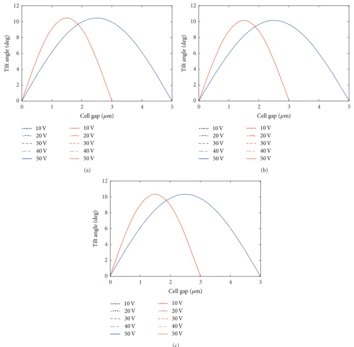
Figure 7: Comparison of molecule tilt angles between cell gap thicknesses of 3𝜇m and 5 𝜇m when tactile force is applied to LCD screen with (a) 5CB, (b) MBBA, and (c) PAA liquid crystals under different voltages.
In Case 2, which happens when the tactile force is
negligible, the solution for𝜃(𝑡, 𝑧) in (8) is expressed by
𝜃 (𝑡, 𝑧) = 𝑐𝑒−(𝐾𝜋2/𝛾𝑑2)𝑡sin(𝜋𝑧
𝑑 ) , (12)
where 𝑐 is a constant. Since the tactile force is ignored in
Case 2, only Case 1 is further examined.
2.2. Two-Dimensional Model. The above derivation is based
on 1D LC model. Further, this study intends to use (1) to
develop an LC tilt model in two dimensions. Assume that the theoretical model satisfies the following four conditions, as
depicted inFigure 2.
Condition 1. The molecule ignores the moment of inertia;
that is,𝑀 = 0.
Condition 2. Shear rate𝑠 = 𝑠(𝑦) = 𝜕V/𝜕𝑦 = V/(𝑑/3), where V
is the flow velocity and𝑑 is the cell thickness.
Condition 3. The LC sample is homeotropic alignment, and we have the boundary conditions
𝜃 (𝑥, 𝑦, 𝑡) = 𝜃 (𝑥, ±𝑑2, 𝑡) = 0. (13)
Condition 4. The shearing velocity belongs to Poiseuille flow
0 1 2 3 4 5 0 2 4 6 8 10 T il t a n gle (deg) Cell gap (𝜇m) 2.5 dyne 3 dyne 3.5 dyne (a) 0 1 2 3 4 5 0 2 4 6 8 10 12 T il t a n gle (deg) Cell gap (𝜇m) 2.5 dyne 3 dyne 3.5 dyne (b) 0 1 2 3 4 5 0 2 4 6 8 10 14 T il t a n gle (deg) Cell gap (𝜇m) 2.5 dyne 3 dyne 3.5 dyne 12 (c)
Figure 8: Comparison of molecule tilt angles between cell gap thicknesses of 3𝜇m and 5 𝜇m when tactile force is applied to LCD screen with (a) 5CB, (b) MBBA, and (c) PAA liquid crystals under different tactile forces.
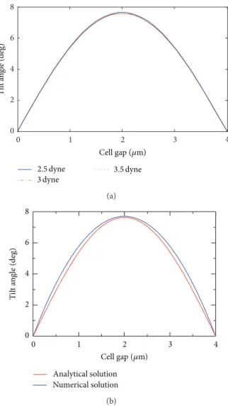
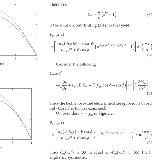
2.5 dyne 3 dyne 3.5 dyne 0 1 2 3 0 2 4 6 8 10 T il t a n gle (deg) Cell gap (𝜇m) (a) 0 1 2 3 0 2 4 6 8 10 12 Numerical solution Analytical solution T il t a n gle (deg) Cell gap (𝜇m) (b)
Figure 9: (a) Comparison of molecule tilt angles depicted in 3𝜇m cell gap 5CB liquid crystals subject to different forces. (b) Comparison of molecule tilt angles subject to 3.5 dyne between analytical and numerical results.
According to the above assumptions, (1) becomes
𝐾 (𝜕2𝜃 𝜕𝑥2 + 𝜕2𝜃 𝜕𝑦2) − 𝛾 𝜕𝜃 𝜕𝑡 + 𝑠 2(𝛾1− 𝛾2cos2𝜃) + 𝜀0𝜀𝑎𝐸2sin𝜃 cos 𝜃 + 𝐹 × ̂𝑛 = 0. (14)
Based on the Ericksen-Leslie theory, (14) represents the tilt
model of LC molecule subjected to both electric field and tactile force. In order to use separation of variables, assume 𝜃 = 𝜃(𝑥, 𝑦, 𝑡) yields
0 1 2 3 0 2 4 6 8 T il t a n gle (deg) Cell gap (𝜇m) 4 2.5 dyne 3 dyne 3.5 dyne (a) 0 1 2 3 0 2 4 6 8 10 Numerical solution Analytical solution T il t a n gle (deg) Cell gap (𝜇m) 4 (b)
Figure 10: (a) Comparison of molecule tilt angles depicted in 4𝜇m cell gap 5CB liquid crystals subject to different forces. (b) Comparison of molecule tilt angles subject to 3.5 dyne between analytical and numerical results.
where 𝑓 (𝑦) = 𝑔 (𝑦) 𝑔 (−𝑦𝑚) ={{{{ { 1 or − 1, 𝑦 = −𝑦𝑚 or𝑦𝑚 𝑔 (𝑦) 𝑔 (−0.28𝑑) = 4.7503 ⋅ 𝑔 (𝑦) , 𝑦 ̸= − 𝑦𝑚 or𝑦𝑚, (16) 𝑔 (𝑦) = 2𝑦𝑑 − sin (𝑦𝜋𝑑 ) , (17) 𝑦𝑚= (𝑑 𝜋) cos−1( 2 𝜋) ≈ 0.28𝑑, (18)
and𝑦𝑚and−𝑦𝑚are boundary conditions of function𝑔(𝑦). In
(15),𝜃𝑚is the angle of the normal vector between the director
of LC molecules with homeotropic alignment. Molecule
0 1 2 3 4 5 0 2 4 6 T il t a n gle (deg) Cell gap (𝜇m) 2.5 dyne 3 dyne 3.5 dyne (a) 0 1 2 3 0 2 4 6 8 Numerical solution Analytical solution T il t a n gle (deg) Cell gap (𝜇m) 4 5 (b)
Figure 11: (a) Comparison of molecule tilt angles depicted in 5𝜇m cell gap 5CB liquid crystals subject to different forces. (b) Comparison of molecule tilt angles subject to 3.5 dyne between analytical and numerical results.
directions are changed by the Poiseuille flow. Values of the
angle along the𝑦-axis have extreme values at 𝑦𝑚 and−𝑦𝑚.
Substituting (15)–(18) into (14) gives
𝐾 [𝜕𝑥𝜕22(𝑓 (𝑦) 𝜃𝑚(𝑥, 𝑡)) + 𝜕
2
𝜕𝑦2(𝑓 (𝑦) 𝜃𝑚(𝑥, 𝑡))]
− 𝛾𝜕𝑡𝜕 (𝑓 (𝑦) 𝜃𝑚(𝑥, 𝑡)) +𝜕𝑦𝜕V(𝛼3sin2𝜃 − 𝛼2cos2𝜃)
+ 𝜀0𝜀𝑎𝐸2sin𝜃 cos 𝜃 + |𝐹| |𝑛| sin (𝜃 − 𝜙) = 0.
(19)
Since|𝑛| = 1, one has
0 1 2 3 0 2 4 6 8 10 T il t a n gle (deg) Cell gap (𝜇m) 2.5 dyne 3 dyne 3.5 dyne (a) 0 1 2 3 0 2 4 6 8 10 12 Numerical solution Analytical solution T il t a n gle (deg) Cell gap (𝜇m) (b)
Figure 12: (a) Comparison of molecule tilt angles depicted in 3𝜇m cell gap MBBA liquid crystals subject to different forces. (b) Comparison of molecule tilt angles subject to 3.5 dyne between analytical and numerical results.
Therefore, (19) becomes 𝐾 {[𝑓 (𝑦)𝜕2𝜃𝑚 𝜕𝑥2 + 0] + [𝜃𝑚𝜕 2𝑓 (𝑦) 𝜕𝑦2 + 0]} − 𝛾𝑓 (𝑦) 𝜕𝜃𝑚 𝜕𝑡 +𝜕V 𝜕𝑦[𝛼3sin2(𝑓 (𝑦) 𝜃𝑚) − 𝛼2cos2(𝑓 (𝑦) 𝜃𝑚)] + 𝜀0𝜀𝑎𝐸2sin(𝑓 (𝑦) 𝜃𝑚) cos (𝑓 (𝑦) 𝜃𝑚) + 𝐹 sin (𝑓 (𝑦) 𝜃𝑚− 𝜙) = 0. (21)
As depicted inFigure 2, the director makes an angle𝜃𝑚with
the𝑦-axis. Consequently, 𝜃𝑚represents liquid crystal
mole-cules with homeotropic alignment caused by the Poiseuille
flow between director̂𝑛 and normal direction of LC sample.
An effective director equation of motion with the essential
physics preserved may be obtained by setting𝑦 = −𝑦𝑚 and
𝑦 = 𝑦𝑚in (21). 0 1 2 3 4 0 2 4 6 T il t a n gle (deg) Cell gap (𝜇m) 2.5 dyne 3 dyne 3.5 dyne (a) 0 1 2 3 0 2 4 6 8 Numerical solution Analytical solution T il t a n gle (deg) Cell gap (𝜇m) 4 (b)
Figure 13: (a) Comparison of molecule tilt angles depicted in 4𝜇m cell gap MBBA liquid crystals subject to different forces. (b) Comparison of molecule tilt angles subject to 3.5 dyne between analytical and numerical results.
On boundary𝑦 = −𝑦𝑚inFigure 2, 𝐾𝜕2𝜃𝑚 𝜕𝑥2 − 𝛾 𝜕𝜃𝑚 𝜕𝑡 + 𝜕V 𝜕𝑦(𝛼3sin2𝜃𝑚− 𝛼2cos2𝜃𝑚)
+ 𝜀0𝜀𝑎𝐸2sin𝜃𝑚cos𝜃𝑚+ 𝐹 sin (𝜃𝑚− 𝜙) = 0.
(22)
By using trigonometric formulas, one can rewrite (22) as
𝐾𝜕2𝜃𝑚 𝜕𝑥2 − 𝛾 𝜕𝜃𝑚 𝜕𝑡 + 𝜕V 𝜕𝑦 × [𝛼3(1 − cos 2𝜃𝑚 2 ) − 𝛼2( 1 + cos 2𝜃𝑚 2 )] + 𝜀0𝜀𝑎𝐸2𝜃
𝑚+ 𝐹 (sin 𝜃𝑚cos𝜙 − cos 𝜃𝑚sin𝜙) = 0.
0 1 2 3 4 5 0 2 4 6 T il t a n gle (deg) Cell gap (𝜇m) 2.5 dyne 3 dyne 3.5 dyne (a) 0 1 2 3 0 2 4 6 8 Numerical solution Analytical solution T il t a n gle (deg) Cell gap (𝜇m) 4 5 (b)
Figure 14: (a) Comparison of molecule tilt angles depicted in 5𝜇m cell gap MBBA liquid crystals subject to different forces. (b) Comparison of molecule tilt angles subject to 3.5 dyne between analytical and numerical results.
Because sin𝜃𝑚 ≈ 𝜃𝑚 and cos𝜃𝑚 ≈ 1 for small 𝜃𝑚, (23) is
rewritten as 𝐾𝜕𝜕𝑥2𝜃2𝑚 − 𝛾𝜕𝜃𝜕𝑡𝑚 +𝜕𝑦𝜕V[𝛼3(1 − 12 ) − 𝛼2(1 + 12 )] + 𝜀0𝜀𝑎𝐸2𝜃 𝑚+ 𝐹 (𝜃𝑚cos𝜙 − sin 𝜙) = 0. (24) Thus, 𝐾𝜕2𝜃𝑚 𝜕𝑥2 − 𝛾 𝜕𝜃𝑚 𝜕𝑡 − 𝛼2 𝜕V 𝜕𝑦+ 𝜀0𝜀𝑎𝐸2𝜃𝑚 + 𝐹 (𝜃𝑚cos𝜙 − sin 𝜙) = 0. (25) Hence, 𝛾𝜕𝜃𝜕𝑡𝑚=𝐾𝜕𝜕𝑥2𝜃𝑚2 − 𝛼2𝜕𝑦𝜕V+ 𝜀0𝜀𝑎𝐸2𝜃𝑚+ 𝐹 (𝜃𝑚cos𝜙 − sin 𝜙). (26) 0 1 2 3 0 2 4 6 8 10 12 T il t a n gle (deg) Cell gap (𝜇m) 2.5 dyne 3 dyne 3.5 dyne (a) 0 1 2 3 0 2 4 6 8 10 12 14 Numerical solution Analytical solution T il t a n gle (deg) Cell gap (𝜇m) (b)
Figure 15: (a) Comparison of molecule tilt angles depicted in 3𝜇m cell gap PAA liquid crystals subject to different forces. (b) Comparison of molecule tilt angles subject to 3.5 dyne between analytical and numerical results.
Substituting𝜃𝑚 = 𝜃𝑚(𝑡) sin(𝜋𝑥/𝑑) for separation of variables
into (26) leads to 𝛾 ̇𝜃𝑚 = 𝐾 𝜕2 𝜕𝑥2[𝜃𝑚(𝑡) sin (𝜋𝑥𝑑 )] − 𝛼2𝜕𝑦𝜕V + 𝜀0𝜀𝑎𝐸2𝜃𝑚+ 𝐹 (𝜃𝑚cos𝜙 − sin 𝜙) . (27) As a result, 𝛾 ̇𝜃𝑚= −𝐾𝜋2 𝑑2 𝜃𝑚(𝑥, 𝑡) + (𝜀0𝜀𝑎𝐸2+ 𝐹 cos 𝜙) 𝜃𝑚 + (−𝛼2𝜕V 𝜕𝑦− 𝐹 sin 𝜙) . (28)
0 1 2 3 0 2 4 6 8 T il t a n gle (deg) Cell gap (𝜇m) 4 2.5 dyne 3 dyne 3.5 dyne (a) 0 1 2 3 0 2 4 6 8 10 Numerical solution Analytical solution T il t a n gle (deg) Cell gap (𝜇m) 4 (b)
Figure 16: (a) Comparison of molecule tilt angles depicted in 4𝜇m cell gap PAA liquid crystals subject to different forces. (b) Comparison of molecule tilt angles subject to 3.5 dyne by analytical and numerical results.
Similarly, we consider the following two cases.
Case 1 −𝛼2𝜕V𝜕𝑦+ 𝜀0𝜀𝑎𝐸2𝜃𝑚+ 𝐹 (𝜃𝑚cos𝜙 − sin 𝜙) ≫ 𝐾 𝜕2𝜃 𝑚 𝜕𝑥2 , (29) 𝛾 ̇𝜃𝑚= (𝜀0𝜀𝑎𝐸2+ 𝐹 cos 𝜙) 𝜃 𝑚+ (−𝛼2𝜕V𝜕𝑦− 𝐹 sin 𝜙) . (30)
Assuming ̇𝜃𝑚 = 𝑎 + 𝑏𝜃𝑚, one has
𝑎 = 1 𝛾(−𝛼2 𝜕V 𝜕𝑦− 𝐹 sin 𝜙) , 𝑏 = 1 𝛾(𝜀0𝜀𝑎𝐸2+ 𝐹 cos 𝜙) . (31) 𝜃𝑚= 𝑎𝑏(𝑒𝑏𝑡− 1) (32)
is the solution. Substituting (31) into (32) yields
𝜃𝑚(𝑥, 𝑡) =[−𝛼𝜀2(𝜕V/𝜕𝑦) − 𝐹 sin 𝜙 0𝜀𝑎𝐸2+ 𝐹 cos 𝜙 (𝑒 ((𝜀0𝜀𝑎𝐸2+𝐹 cos 𝜙)/𝛾)𝑡− 1)]sin(𝜋𝑥 𝑑 ). (33) Consider the following.
Case 2 −𝛼2𝜕V𝜕𝑦+ 𝜀0𝜀𝑎𝐸2𝜃𝑚+ 𝐹 (𝜃𝑚cos𝜙 − sin 𝜙) ≪ 𝐾 𝜕2𝜃 𝑚 𝜕𝑥2 . (34)
Since the tactile force and electric field are ignored in Case 2,
only Case 1is further examined.
On boundary𝑦 = 𝑦𝑚inFigure 2, 𝜃𝑚(𝑥, 𝑡) =[𝛼2(𝜕V/𝜕𝑦) + 𝐹 sin 𝜙 𝜀0𝜀𝑎𝐸2+ 𝐹 cos 𝜙 (𝑒((𝜀0𝜀𝑎𝐸 2+𝐹 cos 𝜙)/𝛾)𝑡 − 1)]sin(𝜋𝑥 𝑑 ) . (35)
Since𝜃𝑚(𝑥, 𝑡) in (33) is equal to −𝜃𝑚(𝑥, 𝑡) in (35), the tilt
angles are symmetric.
3. Discussion
Subject to both electric field of 8.9 V and tactile force,
simulation results for Case 1 are depicted in Figures 3, 4,
and 5. Comparing different LC materials including 5CB,
MBBA, and PAA subjected to 10 ms duration tactile forces
of 1 dyne, 0.5 dyne, and 0.1 dyne at 10 ms, Figures3,4, and5
show that a larger force makes the tilt angle larger regardless
of LC gap thickness. Figures6(a), 6(b), and 6(c)compare
3𝜇m thick different LC materials including 5CB, MBBA, and
PAA subjected to 5 ms duration 0.5 dyne force, respectively. The viscosity of PAA is the smallest and the tilt angle is larger than the others. Therefore, the option of liquid crystal material with smaller viscosity can reduce the ripple.
Tilt angle variations are shown under different voltages in
Figure 7and under different tactile forces inFigure 8. Using 10 V, 20 V, 30 V, 40 V, and 50 V under a tactile force of 3 dyne, it is observed that the tilt angles remain the same in Figures
7(a),7(b), and7(c). Thus, different voltages do not affect tilt
angles.
Based on (33), Figures8(a),8(b), and8(c)compare
differ-ent LC materials including 5CB, MBBA, and PAA subject to
2.5 dyne, 3 dyne, and 3.5 dyne forces in 3𝜇m and 5 𝜇m thick
cell gap LC, respectively. Accordingly, tactile forces affect tilt
angles obviously. Figures9(a), 10(a), and11(a), respectively,
0 1 2 3 4 5 0 2 4 6 T il t a n gle (deg) Cell gap (𝜇m) 2.5 dyne 3 dyne 3.5 dyne (a) 0 1 2 3 0 2 4 6 8 Numerical solution Analytical solution T il t a n gle (deg) Cell gap (𝜇m) 4 5 (b)
Figure 17: (a) Comparison of molecule tilt angles depicted in 5𝜇m cell gap PAA liquid crystals subject to different forces. (b) Comparison of molecule tilt angles subject to 3.5 dyne between analytical and numerical results.
3.5 dyne forces in 3, 4, and 5𝜇m thick cell gap LC. Similarly,
Figures12(a),13(a), and14(a)are MBBA results and Figures
15(a),16(a), and17(a)are PAA results. In addition, Figures
9(b) to 17(b) compare analytical solutions with numerical solutions of the full coupled equations. The comparison results show that analytical solutions are consistent with numerical solutions of the full coupled equations. Therefore, the analytical derivation is validated.
4. Conclusion
The Ericksen-Leslie theory deals with the dynamics of nematic liquid crystals. Based on the Ericksen-Leslie theory, this paper contributes to LC dynamics subject to tactile force. LC molecule tilt leads to a change in the optical intensity transmitted through a liquid crystal cell. LCD panels subject to tactile force will show ripple-like propagation on screens. The present results show that the viscosity, tactile force,
factors of tilt angle variation. Tilt angle variations of PAA liquid crystal molecules are sensitive to tactile force mag-nitudes, while those of 5CB and MBBA with larger viscosity are not. Analytical derivation has been carried out in this study and analytical results have been validated by numerical results.
Acknowledgments
This work was supported by Chi Mei Optoelectronics Corp. and Innolux Display Corp. in Taiwan.
References
[1] J. Ericksen, “Conservation laws for liquid crystals,” Transactions
of the Society of Rheology, vol. 5, pp. 22–34, 1961.
[2] J. L. Ericksen, “Continuum theory of nematic liquid crystals,”
Res Mechanica, vol. 21, no. 4, pp. 381–392, 1987.
[3] F. M. Leslie, “Theory of flow phenomenum in liquid crystals,”
Advances in Liquid Crystals, vol. 4, pp. 1–81, 1979.
[4] F. Brochard, P. Pieranski, and E. Guyon, “Dynamics of the ori-entation of a nematic-liquid-crystal film in a variable magnetic field,” Physical Review Letters, vol. 28, no. 26, pp. 1681–1683, 1972. [5] L. Lei, S. Changqing, S. Juelian, P. M. Lam, and H. Yun, “Soliton propagation in liquid crystals,” Physical Review Letters, vol. 49, no. 18, pp. 1335–1338, 1982.
[6] F. M. Leslie, “Some topics in continuum theory of nematics,”
Philosophical Transactions of the Royal Society A, vol. 309, pp.
155–165, 1983.
[7] J. T. Gleeson, P. Palffy-Muhoray, and W. van Saarloos, “Prop-agation of excitations induced by shear flow in nematic liquid crystals,” Physical Review A, vol. 44, no. 4, pp. 2588–2595, 1991. [8] F. H. Lin and C. Liu, “Existence of solutions for the Ericksen-Leslie system,” Archive for Rational Mechanics and Analysis, vol. 154, no. 2, pp. 135–156, 2000.
[9] L. R. P. de Andrade Lima and A. D. Rey, “Poiseuille flow of Leslie-Ericksen discotic liquid crystal: Solution multiplicity, multistability, and non-Newtonian rheology,” Journal of
Non-Newtonian Fluid Mechanics, vol. 110, no. 2-3, pp. 103–142, 2003.
[10] X. Nie, R. Lu, H. Xianyu, T. X. Wu, and S. T. Wu, “Anchoring energy and cell gap effects on liquid crystal response time,”
Journal of Applied Physics, vol. 101, no. 10, Article ID 103110, 2007.
[11] P. A. Cruz, M. F. Tom´e, I. W. Stewart, and S. McKee, “A numerical method for solving the dynamic three-dimensional Ericksen-Leslie equations for nematic liquid crystals subject to a strong magnetic field,” Journal of Non-Newtonian Fluid
Mechanics, vol. 165, no. 3-4, pp. 143–157, 2010.
[12] X. Nie, H. Xianyu, R. Lu, T. X. Wu, and S. T. Wu, “Pretilt angle effects on liquid crystal response time,” IEEE/OSA Journal of
Display Technology, vol. 3, no. 3, pp. 280–283, 2007.
[13] I. C. Khoo and S. T. Wu, Optics and Nonlinear Optics of Liquid
Crystals, World Scientific, 1993.
[14] I. C. Khoo, Liquid Crystals: Physical Properties and Nonlinear
Optical Phenomena, John Wiley & Sons, New York, NY, USA,
Submit your manuscripts at
http://www.hindawi.com
Hindawi Publishing Corporation
http://www.hindawi.com Volume 2014
Mathematics
Journal ofHindawi Publishing Corporation http://www.hindawi.com
Differential Equations
International Journal of
Volume 2014
Applied MathematicsJournal of
Hindawi Publishing Corporation
http://www.hindawi.com Volume 2014
Hindawi Publishing Corporation
http://www.hindawi.com Volume 2014 Mathematical PhysicsAdvances in
Complex Analysis
Journal of Hindawi Publishing Corporationhttp://www.hindawi.com Volume 2014
Optimization
Journal ofHindawi Publishing Corporation
http://www.hindawi.com Volume 2014
Combinatorics
Hindawi Publishing Corporation
http://www.hindawi.com Volume 2014
International Journal of
Journal of
Hindawi Publishing Corporation
http://www.hindawi.com Volume 2014
Function Spaces
Abstract and Applied Analysis Hindawi Publishing Corporation
http://www.hindawi.com Volume 2014 International Journal of Mathematics and Mathematical Sciences
Hindawi Publishing Corporation http://www.hindawi.com Volume 2014
The Scientific
World Journal
Hindawi Publishing Corporation
http://www.hindawi.com Volume 2014
Discrete Dynamics in Nature and Society Hindawi Publishing Corporation
http://www.hindawi.com Volume 2014
Discrete Mathematics
Journal ofHindawi Publishing Corporation
http://www.hindawi.com Volume 2014
Hindawi Publishing Corporation
http://www.hindawi.com Volume 2014