Proceedings of the American Control Conference Arlington, VA June 25-27, 2001
Adaptive Sliding Mode Controller Design of
a
Dual-Axis Maglev Positioning System
Mei-Ymg Chen', Chin-Chug Wang'
and
Li-Chen Fu',~
1. Department of Electrical Engineering
2.
Department of Computer Science and Information Engineering
National Taiwan University, Taipei, Taiwan, Republic of China.
Abstract
In this paper, a prototype of a dual-axis magnetically levitated positioning platform is proposed and implemented. It is a repulsive maglev system consisting of
two single-axis
positioning sub-systems. First of all, the model of the overall system with complete DOFs (degree-of-fieedoms) is derived and analyzed thoroughIy. Next, an adaptive sliding mode controller which deals with the unknown parameters is well designed to regulate the 12 DOFs in this system. From experimental results, the high performance in terms of sti&ess and resolution has been demonstrated, which quite matches the theoretical Performance.Keywords: Maglev guiding, Hybrid "3, Adaptive sliding mode ~~1
1.
Introduction
Nowadays. High precision planar short-range motion platform is widely adopted in the tremendously booming electronics and/or semiconductor industries. However, this kind of machine device normally needs to work in a very clean environment. With need of such particular feature requirement,
a
larger class of traditional ball-screw type motion platform may not suffice. Therefore, a technology with special kind of actuation subject to some special kindof bearing will then be called for to build the aforementioned device.
Up to now, maglev levitation has spanned many fields, and large volume of literature has been published. Some well known fields include maglev transportation [1][2],
wind tunnel levitation [3], magnetic bearings [4], and anti-vibration tables [5]. Here, however, we will only investigate the maglev techniques for the field of short-range travel with precision positioning and then design and implement a prototype maglev system to verify
its high performance.
Especially electronics andor in semiconductor industry, high precision positioning is one of the most important technologies in all the manufacturing process. These reasons motivate us to design linear magnetic bearing in conjunction with linear motor (modified voice coil motor will be chosen) to achieve the high-precision positioning purpose.
In our foregoing research [6]-[lo], we have analyzed the dynamics of a single-axis maglev guiding system and derived its analytical model The basic concept for system set-up can be referred back to the work by Wang[ 111. In this paper, a more general dual-axis maglev positioning system is built, based on the above-mentioned works. Then, an effective adaptive controller which deals with the unknown parameters is proposed to achieve goals of both accurate guiding and precise positioning. Experimental results are provided to demonstrate the feasibility of such dual-axis set-up and the effectiveness of the developed controller.
2.
System Description and Modeling
The set-up of the dual-axis maglev system consists of gap sensors, voice coil motor(VCM) [lo], levitators and stabilizers, which can generate identical
flux
distribution along the tracks. The perspective and top view of the dual-axis maglev system are shown in Figs. 1-2. The carrier moves along the upper guiding tracks in the Y-axis, whereas the upper guiding tracks moves along the lower guiding tracks in the X-axis. The upper guiding tracks levitate the carrier,and
the carrier and the upper guiding tracks as a whole is called upper position system. Similarly, the lower guiding tracks levitate the upper guiding tracks, and the lower guiding tracks together with the upper guiding tracks is referred to as the lower positioning system.Lower Track Fig ure 1 : Perspective of whole Maglev system.
L I . \ I / I
Figu
'
le"itato/ ' PM'
re 2: The side view of lower guiding system. In carrier design, let the xyz coordinate system be futed on the carrier and the XYZ coordinate system be fixed on the upper track. If these two coordinate systems coincide initially, an arbitrary orientation of the xyz coordinate system can be described in Fig. 3.
curter cester T r u k Cmmid-te
r':r Fig
we 3: Eulerian Angles.
where
e,,$,
and V/ are Eulerian angles of the xyz coordinate system. The transformation fiom xyz- coordinate to XYZ-coordinate can be obtained by performing matrix multiplication of the individual rotation matrices T.In order to achieve the goal of high-precision positioning, we must control translation and attitude of the carrier. To achieve this purpose, a complete analytical model, which includes four lateral DOFs, two propulsion DOFs and six vertical DOFs, will be derived and analyzed thoroughly. Before we proceed with the modeling task, several technical assumptions must be stated. (a).The n-turn wires of the stabilizing and the levitating
coils, which normally come in pairs, are stowed in the coil fiames primly. Each side of the single turn loop wire is viewed as an equivalent long straight current-canying wire which is parallel to all the other wires.
(b).Each magnet is made of NdFeB characterized by uniform magnetization.
(c).The tracks are relatively long with respect to the travel range of the carrier, so that all the levitation magnets only undergo uniform magnetic fields along the track.
Consider the carrier to be represented by a uniform box shaped object with the center of mass coincident with the center of geometry. The principle of linear momentum leads to the following equations:
F, = mx, Fy = m y , F, = mz
,
(2.1) where F, ,Fy and F, are the resultant forces acting on the carrier along the X-axis, Y-axis and Z-axis, respectively, andm is the mass of the carrier.
By the same token, the principle of angular momentum leads to torque equations for the rotational coordinates. Form Euler's equations[ 121, the dynamics of the rotation variables all with respect to the carrier coordinate can be described as follows:
TI = InhI
+
(Izx - I,)W~CO,T, = I,h,
+
(Z,
-
I x r ) ~ y ~ ,Ty = ',by + ( I ,
-
Z,)W~O,,
(2.2)where T,,T, and T, are the external torques, I,, I , andl, are the principal moments of inertia, and w,,oY and W, are the three angular velocities of the rigid
body.
The equations of force and torque on a magnet induced by an infinitely long current-canying straight wire can be rewritten as in the following forms suitable which are the most relevant to this maglev system[S]:
m p I (z2-x2) 271 (x'
+2)*
2 x (x*+z')* ' F,(x,z,I) = A F,(x, 2, I ) =-
m,pJ -2xz T ( x , Z , I ) =--
mzpoz i = T ( x , z , I ) i . (2.5) 2n x 2 + z 2The forces and torque acting on the levitation magnet are fiom levitators and stabilizers. The notation of m, is the dipole moment of infinitesimal current loop, po is the permeability of free space, and I is input current.
Before formulating equations of motion, some notations on force and torque are explained in the following: the subscript has three letters, the first means the direction of force, the second is magnet location, and the last means the coefficient for state or input, e.g. KmZ is the coefficient of
the force on magnet A in the X-direction associated with vertical displacement Sz
,
K,, is the coefficient of the force on magnet A in X-direction associated with input current f?om stabilization coil, and KuI is the coefficient of the force on magnet A in Z-direction associated with input current fkom levitation coil. Then, each permanent magnet is exerted by two magnetic forces, namely, Fx4,
Fu
and TyA,
which can be linearized as in the following equations:F, = KW S x
+
K,,6 z
+
K,,6 I ,TyA = KyAS x
+
KyA18 I.
(2.6) (2.8) Fa = K , 6 x + K u , S z + K a , 6 1 , (2.7)
P
,
G
f,
4 v aJ
I Hi
!\-F
: r 7 . . ..._... .. ... I ... . ... .. . , . .__._ .. .. .. ... . ... . ... ... ... .. A Yl a
' A B E D F ma
IFigure
4:
Top
viewof
Maglev positioningsystem
The locations of the levitation magnets are shown in Fig. 5. Combine these small displacement (the subscript U denotes
carrier and
I
denote signals conceming the upper track) withEq.(2.6) to Eq.(2.8), we can derive the interaction force between a magnet and a track. By means of magnetic force functions, the complete set of analytical equations of motion can be obtained (More detailed modeling process and
+X
3.Controller Design and Stability Analysis
In the previous section, though complete derivation of model is described, we have made several assumptions, which will inevitably result in modeling errors. Therefore, the controller to be developed should be robust enough to tolerate these system uncertainties and m o d e l e d dynamics. Besides these uncertainties, the controller also has to eliminate the effect due to disturbances. In this paper, we adopt an adaptive controller for the task of dual-axis maglev system.
3.1 Controller
Design
In order to obtain a compact controller, redefine the control inputs as
50 50
According to these definitions, we rewrite Eq.(2.9) and Eq.(2.10) into state-space form as:
ME
=A E + BU+CG
+
DH
+
w
(3.3)where E is state variable vector, U is control input, G and H are nonlinear terms which are caused by platform moving. The extemal disturbances and high order terms resulting fiom linearization are modeled as a column vector,
W.
Besides, there are four primary factors that account for uncertainties. Additionally, v are modeled here in order to cancel the sensor calibration error. These errors are due to the mismatches of the actual neutral points (tracks) and the set neutral points (sensors). Rewrite the Eqs. (3.3)
D,% = -D,E
+
U
+
v,
(3.4) whereE=W, 0,
z,
4,
v,
xu
0, Z" #JUvuP,
U =
[U,...
ulOlr, v =[VI...
vlo]r,D,4=dag(all, %Z¶***, q O I O ) , DB=diag(bil, b S z , - , b i O l O ) *
Thus, a compact form of the overall system model is derived.
We assume a sliding surface S, which satisfies:
s
=cDE
-+
G~
E,
(3.5) where GD =[$I.*.
a&O1r,G=[4I
$2 .** 4 l O r 2 hdi >and >O, Vi=l-10, and we find that S depends on error column vector E and its time derivatives. For our applications, we are to regulate every entry in the error column vector E to zero. In the mean time, the time derivatives of every entry in E, which are denoted as E , also have to be regulated to zero to ensure the errors included in column vector E stay at zero. Due to this reason, if we can prove the sliding surface tends to zero within finite time, then we can assure E and
E
also are forced to zero exponentially. To relate the sliding surface to the dynamics of motion, we find out the time derivative of the sliding surface is:S
= G,E+ G ~ E . (3.6) As described in the previous section, we apply an adaptive controller here, which is capable of estimating parameters of system on-line and controlling the system simultaneously. After we have the estimates of system parameters, we can use Eq.(3.6) with these estimates in the control command. So, we substitute tlie estimates acquired from the on-line estimator and derive the following:u=~~G,,-'(-KG+KG,E-G& +5p-&-~9(3.7)
where
fi,
,
fi,
,
6
, and
i are the estimates ofDB
,
DA G,
and v ,respectively, andK = [ k , k2
...
k l O ] r y4
>O,
Vi=1-10,s;
>q
s, <-E, Thus, substituting Eq.(3.7) into Eq.(3.5), we can obtain
D,[G,-'$+
K(G,-'S)] =-bA
E+G+Vwhere the estimation errors are defined as
6B=DB-bB,
5"=DA-bA
, G = C - 6
and V = v - i . Byapplying appropriate
K,
GD and G p , we can accelerate the convergence and force them to zero in a shorter period of time.3.2
Adaptive Laws
In the previous section, we have derived the close-loop function in Eq.(3.8), which involves estimation errors. Now, with the help of estimator based on adaptive control theory, then we can derive the estimates, so that appropriate control commands are also derived.
We define a Lyapunov function candidate V, which is a positive definite function:
12
-STG,-~D,TD,KG,-'S
-
/sf1
s
o
141
>%-STG,-'D,TD,KG;'S-C~,
5
<o
lsil 5% d3.13) ,=I 12 2=-I
,=II&,/
-
because GD-'
,
DE and K are all positive diagonal matrices so that they are commutable in deriving the inequality. And Eq.(3.13) also implies that the equilibriumDA =
bA,
DE =bB G=d
and v = $ of the respectiveequations is uniformly bounded. Using arguments similar to Lyapunov theory we establish that S E L~
, S E &
and that: [S(t)l+ O,
llfiAll-+
0,
llO,ll+
0,
IlGll--+
0 and11.11+0
as t + m .Due to zero convergence of S , it can be readily verified that every entry in column vector E coverage to zero asymptotically. In other words, state variables and their time derivatives all converge to zero eventually, which is the goal of designing the controller for this system.
4.
Experimental Results
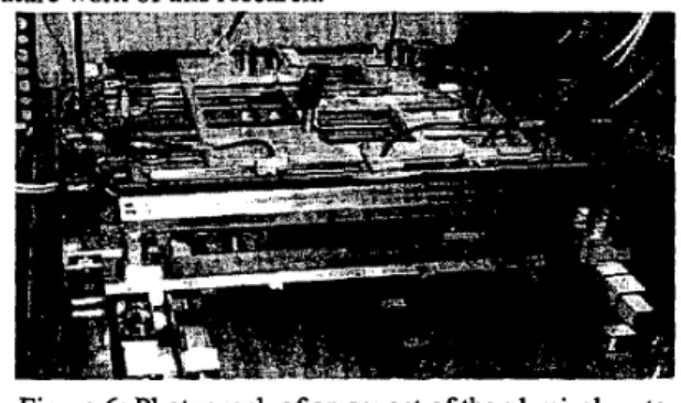
The design of overall system is thoroughly described in section 2. Figure 6 shows the photographs of the physical set-up.
A number of experimental results including the transient and the steady-state responses will be provided in this section to demonstrate the performance of this system with controller presented in section 5. Based on these results, we will make some conclusions which are important for the
Figure 6: Photograph of an aspect of the physical system. From experimental results shows in Fig.7, we can observer that the carrier
has
oscillation in transient response part. It iscause of system magnetic line of force coupling between carrier and upper track. In the system steady state part, carrier guiding resolution is lxlO-'m and upper track guiding resolution is 3 x IO'm. We list the experimental data here. These experimental
data
reveal that adaptive controller successlllyregulate all the attitudes of the dual-axis maglev system.
. . , .
’* Y .I I. a.
.
I ,..
.9 1. *L
(a) carrier (b) upper track Figure 7: System transient and steady state response of
carrier and upper track.
5.
Conclusion
Throughout the research presented in this paper, a dual-axis maglev positioning platform was proposed, and a stabilizing and levitating of the system controller is well developed. The dynamics of the positioning system have been analyzed and then its model is also derived. An adaptive controller is designed here because the systems parameters are difficult to know precisely in such a system. From the experimental results, the feasibility and effectiveness have been demonstrated. Moreover, by k i n g permanent magnets into tracks as levitation devices, the power consumption of
this system is considerably saved. A novel power-saving and high precision positioning maglev X-Y table is successhlly accomplished.
6.Bibliography
[I]. B. V. Jayawant, P. K Sinha, and D. G. Aylwin, “Feedback Control System for D.C. Electromagnets in Passenger-Canying Vehicles”, Int. J. Control, vol. 24, No. 5, pp. 627439, 1V6
[2]. M. Proise, et al.:“System Concept Definition of the Grumman Superconducting Electromagnetic Suspension
(EMS) Maglev Design”, Maglev ‘93 Con$ Argonne
National Laborutov, May 19-2 1,1993
[3]. E. E. Covert, M. Vlajinac, T. Stephens, and M. Finston,“Magnetic Balence and Suspension Systems for Use with Wind Tunnels”, Progress in Aerospace Science, vol. 14., ed. D, Kuchemann, pp.27-107, Pergamon Press, 1973.
[4]. T. Higchi, Magnetic Bearings. Proc. 1st Int. Symposium on
Magnetic Bearings. Univ. of Tokyo.1990.
[ 5 ] . N. Kosuke, and I. Masadi, “A Noncordact Permanent Magnet
Levitation Table with Electromagnetic C ” 1 and 16 Vibration Isolation Method Using Direct Dkhxbance Cancellation Combining Optimal Regulzbors’: lEEE
T m
on Magnetics ,vol. 31,110.1, Jan 1995.[ 6 ] . M. Y. Chen, K. N. Wu and L.C. Fu, “Adaptive Control and Experiment of a Maglev Guiding System for wafer Transportation”, I.F.A.C. Worhhop on Motion Control
Cogerence, 1998
[7] M. Y. Chen, K N. Wu and L.C. Fu, “Design, Implementation and Self-tuning Adaptive Control of a Maglev Guiding System”, Mechatronic, pp. 215-237,2000
[8].
M.
Y. Chen, M. J. Wang and L.C. Fu, ‘‘Modeling and Controller Design of a Maglev Guiding System for Application in Precision Positioninf, American ControlCogerence, 1999
Guiding System Modeling and Controller Design for Wafer Transporkition”, Control andDechion ConfkrenceJ999 (101. C. C. Wang , M. Y . Chen and L.C. Fu, “Adaptive Sliding
Mode Controller Design of a Maglev Guiding System for
Application in Precision Positioning, American Confrol
Con$erence,2,2000
[ I l l . I. Y. Wan& “A Magnetic Levitation Silicon Wafkr Transport
System”. Ph.D.’Ihesis,TneUniv~~ofTexasatAustin, 1993. [WDavid L. Trumper, Sean M. Olson, and pradeep K.
Subrahmanyan, “Linearizing Control of a Magnetic Suspension Systems” IEEE trm on Control Systems
Technology. vol. 5, no. 4, July 1996.
[I31 Jean-Jacques E. Slotine, Weiping Li., Applied nonlinear
control, Prentice Hall, 1990.
1141. Chin-Chung Wang “A Dual-& MugLev Positioning
System” Master thesis. The National Taiwan University,
Taiwan, RO.C., 2000.
[9]. M. Y. Chm, M. J. Wang and L.C. Fu, “DUal-Axis Maglev
7. Acknowledgement
RO.C., under the grant NSC 88-2213-E402484