Compact Microstrip Bandpass Filters with
Quarter-Wavelength Stepped-Impedance Resonators
Shih-Cheng Lin, Yo-Shen Lin, and Chun Hsiung Chen
Department of Electrical Engineering and Graduate Institute of Communication Engineering, National Taiwan University, Taipei 106, Taiwan, Tel: +886-2-23635251-221, Fax: +886-23683824 Abstract — Compact microstrip bandpass filters
utilizing quarter-wavelength (Ȝ/4) stepped-impedance resonators (SIRs) are proposed. The Ȝ/4 SIR has the abilities to reduce the filter size and to push up the filter spurious frequency. By arranging Ȝ/4 SIRs properly in the filter layout, two compact 4th-order microstrip bandpass filters with extended rejection band and good selectivity are designed and implemented. Specifically, a miniature Ȝ/4-SIR 6th-order cross-coupled microstrip bandpass filter with a size of only 0.3Ȝ×0.17Ȝ is realized to possess a better rejection up to 3.6f0, where f0 denotes the passband center frequency.
I. INTRODUCTION
For application in wireless communication, filters with compact size are extremely important to miniaturize the system volume. The function of filter is to choose the required frequency band and to suppress out-of-band frequencies. Therefore, the selectivity is a key performance index for filters utilized in the wireless system. Cross-coupled bandpass filters (BPFs) with multiple transmission zeros have been widely used in the filter design for their improved selectivity. However, the conventional filters using half-wavelength (Ȝ/2) resonators may occupy larger area and also suffer from the presence of a second passband at twice the fundamental resonance frequency (2f0) [1]-[3].
To solve the problem of large size and too close spurious passband at 2f0, the Ȝ/4 resonators were adopted
to design several cross-coupled bandpass filters [4]-[6]. Conventional combline and interdigital filters of direct-coupled form based on Ȝ/4 resonators possess no additional cross-coupled path to provide extra transmission zeros [7]-[8]. The first cross-coupled filter with Ȝ/4 resonators was proposed in [4], in which the cross coupling between nonadjacent resonators was realized by aperture coupling through the ground plane of the dual-plane structure. In [5] and [6], the electrical or magnetic cross coupling is achieved by bending the open-ends of Ȝ/4 resonators or connecting the short-ends of folded Ȝ/4 resonators. In addition to size reduction, the use of Ȝ/4 resonators can also push the second passband to 3 times the fundamental frequency (3f0). One can
further reduce the filter size and obtain extra advantage of extending the rejection bandwidth by utilizing the Ȝ/4 SIRs [9].
In this paper, several microstrip bandpass filters utilizing Ȝ/4 SIRs are proposed. The proposed 4th-order filters feature very compact size and extended rejection band. Cross coupling is also introduced to achieve
transmission zeros for improving the filter selectivity. Finally, a miniature 6th-order cross-coupled microstrip filter is proposed, and it demonstrates very good selectivity with a better rejection up to 3.6f0.
II. FILTERDESIGNS
A. 4th-Order Filter with One Transmission Zero
Shown in Fig. 1(a) is the layout of proposed 4th-order microstrip bandpass filter based on four coupled Ȝ/4 SIRs. The special characteristic of Ȝ/4 SIR is that one can reduce the resonator length and extend the spurious frequency by adjusting the impedance ratio [9]. In order to minimize the filter size, the Ȝ/4 SIRs used in the proposed filters are designed such that the electrical length of the low-impedance section roughly equals to that of the high-impedance one. The impedance ratio is also selected so that the first spurious frequency may further be extended.
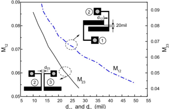
The required coupling coefficients Mij between two
resonators could be calculated from the two natural resonant frequencies associated with the coupled structure [10]. Shown in Fig. 2 is the simulated coupling coefficient versus the spacing between resonators for the proposed filter. Given the required coupling coefficients for a filter specification, one may determine the proper spacing based on Fig. 2. The external quality factor Qe
for the tapped input can be extracted by the method provided in [11]. The tapped position is determined by the required Qe based on the design parameters.
A microstrip Ȝ/4-SIR filter for Fig. 1(a) is fabricated on a Rogers RO4003CTM substrate (İ
r=3.38,
h=20mil=0.508mm, tanį=0.0027). The filter design specification and parameters are listed in Table I. This filter is designed for Butterworth response with the center frequency f0 at 2GHz and the 3dB-FBW of 10%. The
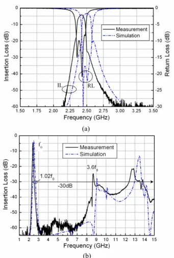
filter has a size of only 14.8mm×10.85mm (0.2Ȝ×0.147Ȝ), which is much more compact than the filters using uniform-impedance Ȝ/4 resonators. The measured and simulated responses are presented in Fig. 3. The measured 3dB-fractional bandwidth (3dB-FBW) is 9.2%. The measured minimum insertion loss is 3.815dB at 2.483GHz. The impedance ratio of the SIR used in this filter is selected as 0.4345; therefore the first harmonic is at 4.439f0. As shown in Fig. 3(b), the first spurious
response of proposed filter is pushed up from 7.5 GHz to 11 GHz (about 4.4f0) as expected. The rejection level of
this proposed filter is better than 30dB from 2.8GHz (1.12f0) to 9.6GHz (3.84f0). Note that one additional
transmission zero at 3.5 GHz is observed. This is because the upper half of resonator 1 acts like an open stub connected to the tapped point, and so does that of resonator 4. As the stub length equals to Ȝ/4 at f0, it will
short the signal to ground and thus produce the transmission zero at upper stopband.
B. 4th-Oder Filter with Two Transmission Zeros
Fig. 1(b) shows the layout of another proposed 4th-order Ȝ/4-SIR BPF with one additional electrical cross-coupling between the input and output, which is accomplished by the coupling between two square loops. The main filter structure is similar to the one presented in Fig. 1(a). The dual square-loop structure may achieve larger amount of electrical coupling than the conventional gap-coupled structure for a given gap width, thus it is easier to fabricate under the process restriction. The additional electrical cross-coupling may introduce one pair of transmission zeros on the two sides of the passband. Shown in Fig. 4 are the measured and simulated frequency responses. The measured 3dB-FBW is about 11.3%. The measured minimum insertion loss is about 4.592dB at 2.523GHz. Two transmission zeros at 2.12GHz and 3.04GHz are observed as expected, which improve the filter selectivity.
C. 6th-Oder Filter with Two Transmission Zeros
Fig. 5(a) shows the layout of proposed cross-coupled microstrip Ȝ/4-SIR bandpass filter of 6th order. The coupling and routing diagram is illustrated in Fig. 5(b). With proper arrangement and deformation of the Ȝ/4 resonators, the filter with high order but with compact size is achieved. The main coupling between resonators 3 and 4 is magnetic coupling, while the cross coupling between resonators 2 and 5 is electrical coupling that is achieved by the gap-coupled capacitance between two open-ends. As a result, a quasi-elliptic response may be obtained [1]. Resonators 1 and 6 are appropriately folded to minimize the size of filter. The impedance ratio of each SIR utilized in this filter is about 0.63, thus the 1st resonance frequency of the SIR is located at 3.68f0. The
filter specification and design parameters are listed in Table I.
Shown in Fig. 6 are the measured and simulated frequency responses of this filter. It provides very sharp frequency slope and two transmission zeros as expected. The measured 3dB-FBW is about 4.1%. The measured passband insertion loss is about 4.16dB at 2.425GHz. The wideband frequency response from 1GHz to 15GHz is presented in Fig. 6(b). The stopband of this filter is extended up to 3.6f0 as shown in Fig. 6(b). The rejection
level is further enhanced on account of the high filter order. The filter size is only about 23mm×12.4mm (0.3Ȝ×0.17Ȝ), which is much smaller than the conventional ones of the same order.
III. CONCLUSION
In this work, several compact microstrip bandpass filters based on Ȝ/4 SIR have been proposed. The Ȝ/4 SIR can effectively reduce the filter size and provides a good stopband rejection with extended rejection band. In
addition, the transmission zeros inherent with the proposed filter structure also improve the filter selectivity. Specifically, a miniaturized 6th-order cross-coupled microstrip bandpass filter with a very compact size has been realized, featuring a better rejection level up to 3.6f0.
This proposed 6th-order quasi-elliptic filter also provides good selectivity which is quite attractive in wireless communication system. Good agreement between measured and simulated results has also been obtained.
ACKNOWLEDGEMENT
This work was supported by the National Science Council of Taiwan under Grant NSC 93-2752-E-002-001-PAE and Grant NSC 93-2219-E-002-021.
REFERENCES
[1] J.-S. Hong and M. J. Lancaster, “Cross-coupled microstrip hairpin-resonator filters,” IEEE Trans. Microwave Theory Tech., vol. 46, pp. 118-122, Jan. 1998.
[2] J.-S. Hong and M. J. Lancaster, “ Couplings of microstrip square open-loop resonators for cross-coupled planar microwave filters,” IEEE Trans. Microwave Theory Tech., vol. 44, pp. 2099-2109, Nov. 1996.
[3] K. Jokela, “Narrow-band stripline or microstrip filters with transmission zeros at real and imaginary frequencies,” IEEE Trans. Microwave Theory Tech., vol. MTT-28, pp. 542-544, June 1980.
[4] S. J. Yao, R. R. Bonetti, and A. E. Williams, “Generalized dual-plane multicoupled line filters,” IEEE Trans. Microwave Theory Tech., vol. 41, pp. 2182-2189, Dec. 1992
[5] C.-C. Chen, Y.-R. Chen, and C.-Y. Chang, “Miniaturized microstrip cross-coupled filters using quarter-wave or quasi-quarter-wave resonators,” IEEE Trans. Microwave Theory Tech., vol. 51, pp. 120-131, Jan. 2003.
[6] C.-Y. Chang and C.-C. Chen, “A novel coupling structure suitable for cross-coupled filters with folded quarter-wave resonators,” IEEE Trans. Microwave Theory Tech., vol. 13, Dec. 2003.
[7] J. S. Wong, “Microstrip tapped-line filter design,” IEEE Trans. Microwave Theory Tech., vol. 27, pp. 44-50, Jan. 1979.
[8] R. J. Wenzel, “Synthesis of combline and capacitively loaded interdigital bandpass filters of arbitrary bandwidth,” IEEE Trans. Microwave Theory Tech., vol. 19, pp. 678-786, July 1971.
[9] M. Sagawa, M. Makimoto, and S. Yamashita, “Geometrical structures and fundamental characteristics of microwave stepped-impedance resonators,” IEEE Trans. Microwave Theory Tech., vol. 45, pp. 1078-1085, July 1997.
[10] J.-S. Hong, M. J. Lancaster, “ Couplings of microstrip square open-Loop resonators for cross-coupled planar microwave filters,” IEEE Trans. Microwave Theory Tech., vol. 44, pp. 2099 2109, Nov. 1996.
[11] J.-S. Hong and M. J. Lancaster, Microstrip Filters for RF/Microwave Applications, 1st ed., Wiley, 2001.
Fig. 1. (a) Proposed 4th-order Butterworth microstrip Ȝ/4-SIR BPF. (b) 4th-order cross-coupled microstrip Ȝ/4-SIR BPF with additional electrical cross-coupling introduced by the novel dual square-loop structure as indicated by the dotted circle.
5 10 15 20 25 30 35 40 45 50 55 0.05 0.06 0.07 0.08 0.09 0.04 0.05 0.06 0.07 0.08 0.09 M12 M23 M12 d12 and d23 (mil) M23 20mil d12 1 2 2 3 d23
Fig. 2. Coupling coefficients versus resonator spacings for the two types of coupled structures in proposed filters in Fig. 1.
Fig. 3. Measured and simulated frequency responses of the proposed filter in Fig. 1(a). (a) Narrowband and (b) wideband.
1.5 2.0 2.5 3.0 3.5 -80 -70 -60 -50 -40 -30 -20 -10 0 -40 -30 -20 -10 0 IL Measurement Simulation Insertion Loss (dB) Insertion Loss (dB) Frequency (GHz) RL
Fig. 4. Measured and simulated frequency responses of the proposed filter in Fig. 1(b).
(a)
(b) Table I.
Design Parameters of proposed BPFs
Filter layout FBW Filter type Design Parameters Fig 1(a) 10% Butterworth4-pole
Qe1=Qe4=7.654
M12=M34=0.0841
M23=0.0541
Fig. 6 5% Quasi-elliptic6-pole
Qe1=Qe6=20.2
M12=M56=0.0415
M23=M45=0.029
Fig. 5. (a) Layout of the proposed 6th-order cross-coupled microstrip Ȝ/4-SIR BPF. (b) Coupling and routing diagram for the filter in Fig. 5(a).
Fig. 6. Measured and simulated frequency responses of the filter in Fig. 5. (a) Narrowband and (b) wideband.
(a)