P
erformance analysis of a solar-assisted heat pump water heater
*
J.P. Chyng, C.P. Lee, B.J. Huang
Department of Mechanical Engineering, National Taiwan University, Taipei 106, Taiwan
Abstract
A modeling and system simulation of an integral-type solar assisted heat pump water heater (ISAHP) was carried out in the present study. The modeling and simulation assumes a quasi-steady process for all the components in the ISAHP except the storage tank. The simulation results for instantaneous performance agreed very well with experiment. The simulation technique was used to analyze the daily performance of an ISAHP for 1 year. It is shown that the daily total COP (COP ) iso around 1.7 to 2.5 year around for the ISAHP, depending on seasons and weather conditions. COP is higher than 2.0 for mosto of the time in a year and the daily operating time varies from 4 to 8 h. The online adjustment requirement of the expansion valve was also investigated using the present simulation technique. The analysis shows that the expansion device does not need to be controlled online. Using the 1-year simulation results, a universal daily performance correlation of the ISAHP was derived and shown experimentally to be applicable to another design of ISAHP.
2003 Elsevier Science Ltd. All rights reserved.
1
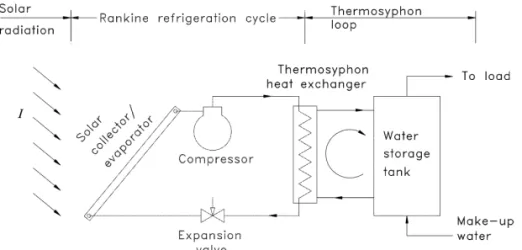
. Introduction simultaneously. The water in the tank is heated from cold to hot (about 60 8C) daily. This makes the Rankine A direct expansion solar assisted heat pump (SAHP) refrigeration cycle operate in a time-variable state. In water heater consists of a Rankine refrigeration cycle addition, the weather conditions may vary severely and coupled with a solar collector that acts as an evaporator. randomly, minute by minute or day by day. The operation The refrigerant is directly expanded inside the evaporator of an ISAHP is therefore non-steady state. The regulation to absorb the solar energy. By a proper design of the of the expansion device in the ISAHP thus can be a Rankine refrigeration cycle and the collector for a specific problem. In the present study, we carried out a system operating condition, heat may be absorbed from, rather analysis for an ISAHP to understand the performance of than rejected to, the ambient. That is, SAHP can absorb the ISAHP including the required regulation of the expan-heat from solar radiation and ambient air simultaneously sion device. Both instantaneous, daily and yearly per-(Huang and Chyng, 2001).Huang and Chyng (1999)first formance characteristics are studied. The analytical results proposed the design of an integral-type solar-assisted heat are then compared with experimental data. The present pump water heater (ISAHP) that integrates the heat pump, study focuses on the performance of an ISAHP designed solar collector and water storage tank together to come up and fabricated previously by Huang and Chyng (2001). with a single unit that is easy to install (seeFig. 1).Huang The schematic diagram is shown inFig. 2.
and Chyng (2001) further studied experimentally the instantaneous performance characteristics of an ISAHP
2
. Prototype design of an ISAHP operating at a near saturated-vapour state at the inlet of the
compressor. It was also observed in the experiment that the
The ISAHP prototype used a bare collector / evaporator. expansion valve needs online adjustment in order to keep
The collector is of tube-in-sheet type using copper tube the ISAHP operating at a near saturated-vapour state. This
(6 mm diameter) and copper sheet (0.4 mm thick). Copper implies that an automatic control system of the expansion
tubes are soldered on the copper sheet. The collector valve may be required for the ISAHP.
surface is divided into four parts: one top surface (50 cm3 An ISAHP absorbs solar radiation and ambient heat
74 cm), one front surface (50 cm3120 cm) and two side surfaces (60 cm374 cm each), as shown in Fig. 3. The
*Corresponding author. Tel.: 1886-2-2363-4790; fax: 1886-2- 2
total surface area of the collector is 1.86 m . The collector 2364-0549.
surface is painted in black. Three refrigerant flow channels E-mail address: bjhuang@seed.net.tw(B.J. Huang).
0038-092X / 03 / $ – see front matter 2003 Elsevier Science Ltd. All rights reserved. doi:10.1016 / S0038-092X(03)00110-5
Nomenclature
2
Ac area of solar collector, m
B and B0 1 flow friction parameters in Eq. (2)
c fitted constant,
21 21
cp,w specific heat of water, J kg 8C
COPo daily total coefficient of performance (COP) the total energy absorbed by water / total electrical consumption
D inner diameter of water tank, m
Gr Grashof number
H height of water tank, m
Hth thermosyphon pressure head, m H O2
22 21
Ht daily total solar irradiation, J m21 day
h enthalpy, J kg
22
I solar irradiation upon horizontal surface, W m
L length of thermosyphon heat exchanger, m
Mw total mass of water in the storage tank, kg21
~
m mass flow rate, kg s
21
~
mH water mass flow rate of the tank inlet, kg s 21
~
mL mass flow rate of hot water load from the tank, kg s
21
~
mR refrigerant mass flow rate of the tank inlet, kg s 21
~
mw water mass flow rate in the thermosyphon loop, kg s
N number of stratified layer
P pressure, MPa
Pc condensing pressure, MPa
Pe evaporating pressure, MPa
P1 compressor suction pressure, MPa
P2 compressor discharge pressure, MPa
Pr Prandtl number
Qe evaporation heat rate, W
Qc condenser heat rate, W
Qw daily total energy collection, J
Re Reynolds number
21
RF flow resistance of expansion valve, MPa s kg
21
RF0 daily initial flow resistance, MPa s kg
2 21
SRF rate of change of R , MPa s kgF
t time, s
T temperature, 8C
Ta ambient air temperature, 8C
Ta,av mean ambient air temperature during operation of ISAHP, 8C
Tc condensing temperature, 8C
Te evaporation temperature, 8C
Te,av mean evaporation temperature during operation of ISAHP, 8C
Thx water temperature in the thermosyphon heat exchanger, 8C
Thx,w water temperature in the thermosyphon heat exchanger, 8C
Thx,in water temperature at the inlet of the thermosyphon heat exchanger, 8C
Thx,out water temperature at the outlet of the thermosyphon heat exchanger, 8C
Tin,R refrigerant temperature at the inlet of thermosyphon heat exchanger, 8C
Tout,R refrigerant temperature at the outlet of thermosyphon heat exchanger, 8C
Tin,w water temperature at the inlet of thermosyphon heat exchanger, 8C
Tout,w water temperature at the outlet of thermosyphon heat exchanger, 8C
Tw water temperature in the tank, 8C
Tw,av average water temperature in the tank, 8C
Twi daily initial water temperature in the tank, 8C 22 21
Uc heat transfer coefficient between air and collector surface, W m 8C
21
(UA)hx overall heat transfer coefficient in thermosyphon heat exchanger, W 8C21 (UA)e daily overall heat transfer coefficient from ambient to collector, W 8C
3 21
VSD rate of stroke volume of compressor, m s
Wcomp compressor input energy, J
z vertical distance, m
a absorption coefficient of collector surface
as daily total solar energy absorption coefficient, Eq. (22)
a , b ,gi i i Boolean function in Eq. (5)
gw specific weight of water2 21
vw kinematic viscosity, m s
3 21
v specific volume at compressor suction port, m kg
hv volumetric efficiency Subscript a air av average c condenser e evaporator H heating hx heat exchanger
i ith segment of water in tank
in inlet of heat exchanger out outlet of heat exchanger R refrigerant
w water
Fig. 1. Schematic diagram of the ISAHP.
are made along the directions of front-to-top and side-to- refrigeration cycle. A receiver and a filter are installed top, all connected in parallel (Fig. 3). downstream from the condenser and an accumulator is The Rankine refrigeration cycle unit is mounted inside installed downstream from the collector / evaporator to the ISAHP. A small R134a reciprocating-type hermetic protect the compressor from wet compression.
compressor with piston swept volume 5.29 cc, speed 3520 rev. / min and rated input power 250 W is adopted.
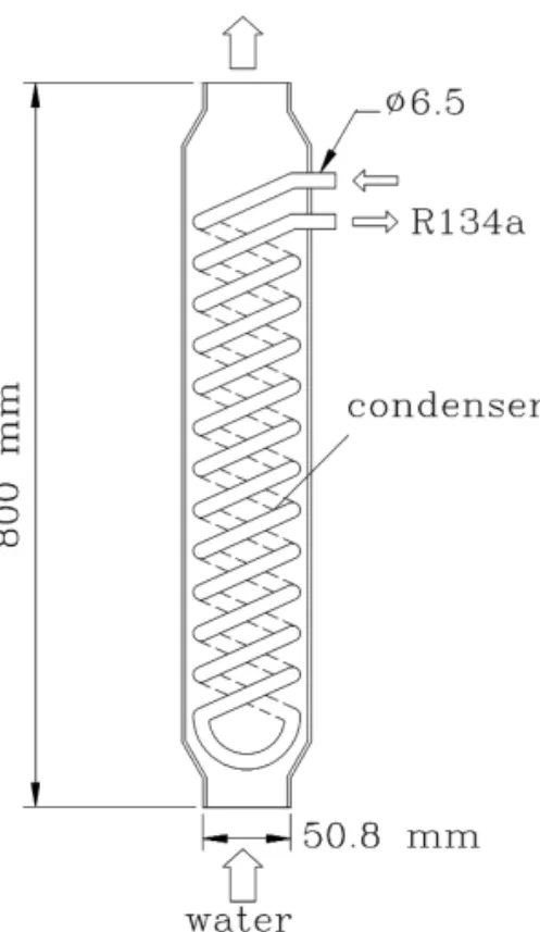
The design of the thermosyphon heat exchanger in the thermosyphon loop is shown inFig. 4.A helical coil made of copper tube with 6 mm diameter is immersed inside a straight water pipe. Water absorbs the condensation heat from the refrigerant vapor inside the copper tube and induces a buoyancy force for natural circulation along the loop. The ISAHP uses a 105-l tank for hot water storage. An expansion valve (Model AEL-1, Egelhof, Germany) is used for regulating the refrigerant flow in the Rankine
Fig. 2. Schematic diagram of the integral-type solar assisted heat
Fig. 3. Collector surface design of the ISAHP. pump.
where gw is the specific weight of water that can be approximated by the relation:
26 2 25
g (T ) 5 2 4.05 3 10w T 2 3.906 3 10 T
1 1.0002556, T in 8C. (2)
The thermosyphon head Hth generated is used to over-come the flow resistance of the water circulation in the loop that is caused by pipe wall friction and other losses due to valves, bends and fittings, etc. in the loop. It can be assumed that the following quadratic function can be used to describe the loop flow resistance (Huang and Hsieh, 1985):
2
~ ~
H 5 B n m 1 B mf 0 w w 1 w (3) where n is the kinematic viscosity of water and B and Bw 0 1 are the coefficients that can be experimentally determined on site by measuring the mass flow-rate and pressure drop of the loop.
Since the variation of the flow-rate of the thermosyphon loop is slow, quasi-steady state can be assumed. Combin-ing Eqs. (1) and (3), the governCombin-ing equation for the momentum balance equation is,
Fig. 4. Design of thermosyphon heat exchanger. L
2
~ ~
E
[g (T ) 2 g (T )] dz 5 B n m 1 B m .w w w hx 0 w w 1 w (4)3
. Mathematical model of the ISAHP
0
As seen from Fig. 1,the ISAHP absorbs energy from Eq. (4) shows that the water flow-rate of the thermosyphon solar radiation and ambient air simultaneously using the loop is affected by the water temperature distribution in the principle of the Rankine refrigeration cycle. The solar tank and the thermosyphon heat exchanger and the loop collector / evaporator combines the evaporator of the Ran- friction. For solving the flow rate, it is necessary to kine cycle and the solar collector. A thermosyphon loop is determine the temperature distributions first.
used to transfer the heat from the condenser to the water
tank via natural circulation. The thermosyphon heat ex- 3 .2. Water temperature distribution in storage tank changer combines the condenser of the Rankine cycle and
the heater of the thermosyphon loop. The circulating flow- The thermal-stratification tank model developed by rate of the thermosyphon loop depends on the water Close (1964) was verified experimentally (Huang et al., temperature variations in the thermosyphon heat exchanger 1984) and has been successfully used in solar collector and in the water tank. The water temperature distribution analysis (Huang and Hsieh, 1985). Close’s model is thus in the thermosyphon heat exchanger is determined by the used in the present study to calculate the water temperature operation of the Rankine cycle that is affected by the distribution in the tank. The tank is divided into N well-design of the Rankine cycle machine and the variations of mixed sections with convection and conduction with solar radiation and ambient conditions. Mathematical adjacent sections. The model assumes that the inlet hot models of the components of ISAHP are derived first. water will flow to a section at the same temperature. An energy balance equation is derived for the ith segment of water (Close, 1964):
3
.1. Momentum balance of the thermosyphon loop
M cw p,w dTi U pDHt
]] ]5]]sT 2 T 1a m ca id i~H p,w
s
T0,w2 Tid
The thermosyphon pressure head Hth induced in the N dt N #%%%%"!%%%%$#%%%"!%%%$
thermosyphon loop can be evaluated by integrating the Heat loss Heat in
water density around the loop. The resulting equation is 1b m ci~L p,w
s
TL,w2 Tid
(5)#%%%%"!%%%%$ Heat out L g ci p,wsTi 212 Tidif g . 0i H 5th
E
[g (T ) 2 g (T )] dz,w w w hx (1) 1H
g c T 2 T if g , 0 s d i p,w i i 11 i 0 #%%%"!%%%$ Internal conductionwhere a, b, g are the Boolean function defined as follows: 3 .5. Rankine cycle model
1 if Ti 21. T . T0 i R134a is the working fluid in the Rankine cycle. The
a 5i
H
(6)refrigerant mass flow rate can be evaluated from the 0 other
volumetric efficiency of the compressor given by the 1 if T . T . Ti L i 11 compressor manufacturer: b 5i
H
(7) 0 other h 3Vv SD ]]] ~ m 5 (13) i 21 N R v ~ ~ g 5 mi HO
a 2 mj LO
b .j (8) j 51 j 5i 11 P 2 ] h 5 2 0.0163 3vS D
P 1 0.6563. (14) 1 Eq. (5) can be solved by the 4th order Runge–Kuttamethod. Using the Simpson 1 / 8 method, integrating the The energy balance of the condenser yields the follow-temperature profile with respect to height, the ther- ing equation, assuming no heat loss:
mosyphon pressure head in the water storage tank is
~
m (h 2 h ) 5 (UA)R 2 3 hx3 LMTD. (15) determined.
For an isenthalpic process in the expansion device, we 3
.3. Condenser heat rejection rate obtain the following equation:
h 5 h .3 4 (16)
Heat rejection from the refrigeration cycle to the water tank occurs via the thermosyphon loop.Dahl and Davidson
3
.6. Solar collector model (1997)have derived experimentally an overall heat transfer
correlation for a water thermosyphon loop heat exchanger
The solar collector acts as the evaporator of the Rankine identical to the present design:
cycle and collector of solar radiation and ambient heat. The 0.43 0.13 0.30 energy balance equation is
(UA)hx5 0.12Pr Re Gr , W/ 8C. (9)
Q 5 aIA 2 U A T 2 T .e c c cs e ad (17) Eq. (9) can be approximated as the overall heat transfer
coefficient from the refrigerant side to the water in the thermosyphon heat exchanger since the water side heat
4
. Simulation procedure of ISAHP transfer dominates the heat transfer process. Pr, Re, Gr
numbers as well as water properties are evaluated at the
The simulation of ISAHP performance includes the average of the inlet temperatures (Tin,R1 Tin,w) / 2 of the
performance computation of the Rankine cycle and ther-heat exchanger. The characteristic temperature difference
mosyphon loop. The Rankine cycle and the thermosyphon in the definition of Gr is Tin,R2 Tin,w.
loop are coupled through the condenser heat transfer. The For a well-insulated heat exchanger, the rejected heat
Rankine cycle is first computed using the given from the Rankine cycle is completely taken away by the
meteorological data I and T . An iteration process isa thermosyphon loop water. Therefore,
required to determine the condenser temperature T . Thec computation starts from an initial guess for T , then
~
m cw p,w
s
Tout,w2 Tin,wd
5 (UA)hx3 LMTD (10) ccompute the Rankine cycle to obtain Q , T , and Q . Q isc e e c then used to compute the water loop performance to where LMTD (log mean temperature difference) is defined
determine the water temperature distribution in the ther-as
mosyphon heat exchanger.
(Tout,R2 Tin,w) 2 (Tin,R2 Tout,w) Computation of the thermosyphon loop performance
]]]]]]]]]
LMTD 5 . (11) starts from an assumed initial water temperature in the tank ln [(Tout,R2 Tin,w) /(Tin,R2 Tout,w)]
and guessing a water outlet temperature at the ther-mosyphon heat exchanger Tw,out. The thermosyphon mass 3
.4. Water temperature distribution in heat exchanger
flow rate mw is first computed from the momentum balance equation of the thermosyphon loop, using the Since the design of the thermosyphon heat exchanger in
known temperature distributions in the heat exchanger and the present ISAHP is a counter-flow type, the temperature
the tank. A new water outlet temperature at the ther-distribution along the flow direction in the waterside can
9
mosyphon heat exchanger Tw,out (denoted Tw,out) can be be approximated by a log function and expressed as
determined using the mass flow-rate mw and Q obtainedc from Rankine cycle computation and the energy balance
Tout,w2 Tin,w
]]]] relation:
~
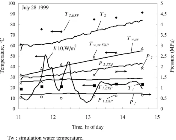
Q 5 m cc w p,w(Tw,out2 Tw,in). (18) in the modeling. The inlet temperature T responds to solar2 radiation variation faster since the thermal capacitance Iteration will proceed if the new Tw,out is not the same as effect of the solar collector is small as compared with the old Tw,outuntil convergence. After convergence of Tw,out, a thermal mass of the water storage tank ( .100 kg).Fig. 5 new Qc can be determined from Eq. (10). Another shows that the solar irradiation is not steady during the iteration in Rankine cycle calculation will proceed by experiment. This causes a larger deviation in the prediction changing T if the new Q is not identical with the old Q ,c c c of vapor temperature T2 since quasi-steady models were until convergence. used for all parts of the simulation except the storage tank. By iteration, the principle of energy balance can be Table 1 shows that the average water temperature conserved for each time step. Repeating the computation prediction is acceptable, mostly within 63 8C error. This again and again for new meteorological data will give the results in an error ,10% for the daily total energy performance of the ISAHP. collection prediction.
5
. Experimental verification of simulation
6
. Performance of ISAHP under various climatic
conditions
Experiments were carried out for the ISAHP built previously (Huang and Chyng, 2001) (Fig. 2). FromTable
Using simulation, we can analyze the daily and long-1, experimental results for the average water temperature
term performance of the ISAHP under various climatic in the tank, Tw,av, are seen to be very close to the
conditions. The present simulation uses 1-year simulation results although the refrigerant vapor
tempera-meteorological data collected on site in the laboratory from ture at the inlet and the exit of the compressor, T and T ,1 2
August 15, 1998 to August 7, 1999. The data contain solar have a larger deviation between experiment and simulation
radiation intensity incident upon the horizontal surface I (Fig. 5). This is due to the ignorance of the dynamic effect
T able 1
Comparison of experiments and simulation
Time Average water temperature in tank Tw,av, 8C
Experiment Simulation Simulation COP Total solar Electricity
2experiment radiation consumption
2 (MJ / m day) (kWh) July 28, 1999 11:04 32.4 31.1 21.3 11:40 38.3 35.8 22.5 12:14 42.4 40.0 22.4 13:11 49.1 46.5 22.6 13:49 53.1 50.6 22.5 14:34 57.4 55.0 22.4 2.4 4.84 1.27 July 30, 1999 11:01 28.4 27.4 21.0 11:13 30.2 28.7 21.5 12:20 40.2 37.4 22.8 14:55 60.8 55.1 25.7 2.8 10.45 1.41 August 2, 1999 10:16 33.7 32.3 21.4 11:09 41.2 39.0 22.2 11:53 46.9 44.4 22.5 13:01 54.9 51.9 23.0 2.63 3.67 0.98 August 3, 1999 10:57 30.7 29.5 21.2 11:23 34.5 32.9 21.6 12:40 44.7 43.0 21.7 13:43 52.5 49.5 23.0 14:41 57.6 54.5 23.1 15:05 59.0 56.5 22.5 2.3 5.05 1.48
Fig. 5. Comparison of experiment (symbols) and simulation (solid lines) for a single day.
and ambient temperature T , both were measured anda conditions was studied. Four typical days representing four averaged for every 3 min. kinds of weather were selected for the study: namely, clear
2
day (15 , H , 20 MJ / mt day, August 19, 1998); partly 2
6
.1. Daily performance analysis cloudy day (10 , H , 15 MJ / m day, August 17, 1998);t 2
cloudy day (5 , H , 10 MJ / mt day, August 16, 1998); 2
The performance of ISAHP under various climatic and rainy day (0 , H , 5 MJ / m day, August 20, 1998).t T
able 2
Performance of ISAHP at 09:00–15:00 h for various weather patterns
2
Weather pattern H , MJ / mt COPo Wcomp, kJ Tw,av, 8C
(total) (final)
Clear day (August 19) 17.9 2.00 10 581 68.1
Partly cloudy (August 17) 12.8 2.00 10 099 66.1
Cloudy (August 16) 9.2 2.01 9724 64.5
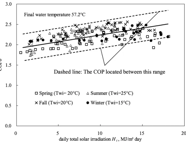
Fig. 6. Variation of daily total COP with solar irradiation.
The simulation results listed inTable 2 reveal that the in summer and fall seasons. Since the COP of a heat pump final water temperature can reach 61 8C by 15:00 h on a water heater increases with decreasing initial water tem-rainy day. In this case, ISAHP absorbs energy mainly from perature and increasing ambient temperature (Huang and ambient air (Huang and Chyng, 2001). Water temperature Lin, 1997), the COP of an ISAHP in summer may not beo of 68 8C can be obtained by 15:00 h on a clear day. The the highest, as indicated inFig. 6. Fig. 6shows that COPo total COPs are higher than 2.0. of an ISAHP is higher than 2.0 for most of the time in a The COP of the ISAHP can be increased if the final year. The daily operation time of the ISAHP is shown in water temperature is set at a lower value. For domestic Fig. 7. The ISAHP operates longer in winter, 6 to 8 h, application, a final water temperature of 57.2 8C (1358F) is depending on daily total solar irradiation and ambient adopted in many places. The simulation was therefore temperature. In summer, the ISAHP will operate between 4 repeated using the 1-year meteorological data and the and 7 h daily, with run times of around 4 to 5 h being results are shown inFig. 6. COP ino Fig. 6represents the typical.
total COP of the ISAHP stopping operation whenever the
average water temperature in the tank reaches 57.2 8C. The 6 .2. Study of expansion valve adjustment for better daily starting time is at 08:00 h in winter season, 08:30 h in performance
spring and fall seasons, and 09:00 h in summer season. It is
seen from Fig. 6 that, for different daily initial water It has been shown in an experimental study (Huang and temperatures, T , in different seasons, COPwi o increases Chyng, 2001) that an ISAHP will operate at a high with increasing daily solar irradiation H . COP is betweent o efficiency if the expansion valve is adjusted online to keep 1.7 and 2.5 throughout the year. In general, COP is highero the refrigerant vapor at the inlet of the compressor close to
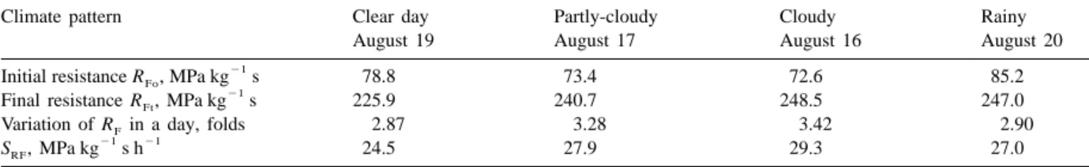
T able 3
Rate of change of expansion valve resistance for different climate patterns
Climate pattern Clear day Partly-cloudy Cloudy Rainy
August 19 August 17 August 16 August 20
21
Initial resistance R , MPa kgFo s 78.8 73.4 72.6 85.2
21
Final resistance R , MPa kgFt s 225.9 240.7 248.5 247.0
Variation of R in a day, foldsF 2.87 3.28 3.42 2.90
21 21
S , MPa kgRF s h 24.5 27.9 29.3 27.0
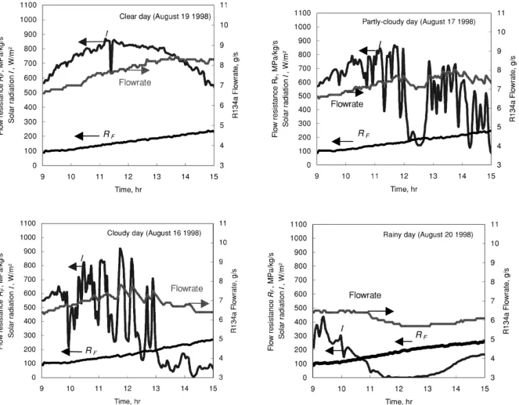
a saturated-vapor state. The simulation tool developed in 6 .3. Study of performance correlation of ISAHP the present study can be used to study the online
adjust-ment of the expansion valve under various climatic con- The simulation technique developed in the present study ditions. The adjustment of the expansion valve opening can be used to derive a correlation for the daily per-can be described using the flow resistance R :F formance of ISAHP. The thermodynamic states at various locations of the Rankine cycle and the temperature
varia-~
R 5 P 2 P /m .F s c ed R (19) tions in the water loop can be calculated using the simulation program and the meteorological data. A daily Fig. 8 shows that RF varies almost linearly with time performance including total heat collection and thermal during a day, irrespective of climatic conditions. This is efficiency can be evaluated.Huang and Chyng (2001)have caused by the large thermal masses of the solar collector derived an instantaneous correlation of ISAHP for the total and water that damp out the effect of solar radiation energy absorption at the evaporator:
variation. The present result indicates that the expansion
valve should be regulated gradually and approximately Q T 2 T
e a e
]5 50.1]]1 0.844. (21)
linearly during a day in order to keep the Rankine cycle at
I I
a saturated-vapor cycle. We can thus describe the
instanta-neous variation of R in the following relation:F Eq. (21) implies that the following correlation may exist for daily performance data:
R (t) 5 RF Fo1 SRFt (20)
T 2 T
Qw a,av e,av
where SRFis the rate of change of R .F Table 3shows that ]5 (UA)e]]]1as (22)
Ht Ht SRFis small and approximately a constant irrelevant of the
climate pattern. One-year simulation results also show that
where Qw is the daily total energy collection in the tank;
SRFis small and approximates a constant as shown inFig.
(UA)e is the daily-total heat transfer coefficient from 9. Figs. 8 and 9 indicate that the ISAHP need not be
ambient air to the refrigerant inside the solar collector; as controlled online as long as the expansion device is
is the solar absorption coefficient representing energy properly designed with a mean resistance value.
collection from solar radiation.
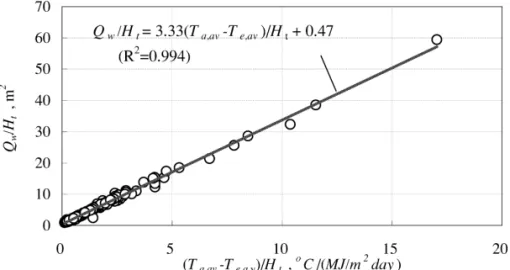
Using 1-year meteorological data, a daily performance simulation was performed and the following correlation was obtained:
T 2 T
Qw a,av e,av
]5 3.33]]] 1 0.47. (23)
Ht Ht
The correlation is satisfactory as shown in Fig. 10. To check the applicability of the correlation (22) to other ISAHPs, an experiment was performed using another ISAHP (ISAHP-B). The design of ISAHP-B is basically the same as ISAHP but larger in size. The specifications are listed inTable 4.The experimental data are seen to fit the above correlation very well but with different parame-ters, as shown in Fig. 11:
T 2 T
Qw a,av e,av
]5 2.36]]]1 0.53. (24)
Ht Ht
Fig. 10. Correlation of daily performance of ISAHP (simulation data).
Fig. 11. Experimental correlation of daily performance of ISAHP-B (experimental data).
7
. Discussion and conclusion ISAHP except the storage tank. The simulation results for instantaneous performance agreed very well with ex-A modeling and system simulation of ISex-AHP for perimental data. The simulation technique is then used to thermal performance analysis was carried out in the analyze the daily performance of ISAHP for 1 year. It is present study. The modeling and simulation assumes shown that the daily total COP (COP ) is around 1.7 to 2.5o quasi-steady operation for all the components in the year round for the ISAHP, depending on season and
T able 4
Design specifications of ISAHP-B
2
Collector area 3.78 m selective surface, unglazed
Water tank 240 l (50 cm diameter, 120 cm tall)
6 cm PU insulation layer
3
Rankine cycle: Compressor / R134a, 600 W/ 110 VAC, 6 cm
weather conditions. COP of the ISAHP is higher than 2.0o A cknowledgements for most of the time in a year and the daily operating time
varies in the range 4 to 8 h. For fixed final water The present study was supported by the Energy Com-temperature at 57.2 8C, the ISAHP operates longer in mission, Ministry of Economic Affairs, Taiwan.
winter (6 to 8 h) and shorter in summer (4 to 7 h). This indicates that the Rankine cycle in the ISAHP is slightly oversized. The water storage capacity can be increased (to
120–150 l) in order to make better use of the heat pump. R eferences It is better to keep ISAHP operating at a nearly
saturated-vapor cycle in order to obtain a better efficiency. C lose, D.J., 1964. The performance of solar water heaters with The online adjustment requirement of the expansion valve natural circulations. Solar Energy 6, 33–40.
D
ahl, S.D., Davidson, J.H., 1997. Performance and modeling of was investigated using the present simulation technique.
thermosyphon heat exchangers for solar water heaters. ASME J. The 1-year simulation result shows that the rate of valve
Solar Energy Eng. 119, 193–200. opening regulation (SRF) is small and approximates a
H
uang, B.J., Hsieh, C.T., 1985. A simulation method for solar constant. This indicates that ISAHP needs not to be
thermosyphon collector. Solar Energy 35 (1), 31–43. controlled online as long as the expansion device is
H
uang, B.J., Lin, F.H., 1997. A compact and fast temperature properly designed with a mean resistance value. This
response heat pump water heater. In: ASME ASIA ’97 Con-coincides with the field test result of the prototype ISAHP. gress & Exhibition, Singapore, September 30–October 2, Paper That used a capillary tube as the fixed expansion device. no. 97-AA-26.
The long-term performance of the ISAHP with a properly- H uang, B.J., Chyng, J.P., 1999. Integral type solar-assisted heat designed capillary tube has shown satisfactory results. pump water heater. Renew. Energy 16, 731–734.
Using the 1-year simulation results, a daily performance H uang, B.J., Chyng, J.P., 2001. Performance characteristics of integral type solar-assisted heat pump. Solar Energy 71 (6), correlation of ISAHP was derived. The correlation, Eq.
403–414. (22), is further experimentally shown to be applicable to
H
uang, B.J., Tsuei, Y.M., Wu, H., 1984. Study of heat transfer in another ISAHP. The system simulation technique
de-thermally stratified tanks. Proc. Natl. Sci. Council Republic veloped in the present study provides a powerful tool for
China Phys. Sci. Eng. 8 (4), 267–276. the design of ISAHP.