ORIGINAL ARTICLE
Ultrasonic vibration-assisted optical glass hot
embossing process
Yen-Pin Tsai&Jung-Chung Hung&Li-Chao Yin&
Chinghua Hung
Received: 19 May 2011 / Accepted: 22 September 2011 / Published online: 2 October 2011 # Springer-Verlag London Limited 2011
Abstract A homemade apparatus was used to apply ultrasonic-vibration to assist the glass hot embossing processes. To operate at high temperatures for glass hot embossing, the ultrasonic vibration system was appropri-ately designed with an embedded cooling system, and an ultrasonic horn was specifically modified for high-temperature use. Molds with both V-groove and Fresnel structures were manufactured for hot embossing experi-ments on PSK-100 glass. The heights of the molded structures were increased significantly with the assistance of ultrasonic vibration. This technology demonstrates the capability to upgrade the performance of the glass hot embossing process.
Keywords Glass hot embossing . Ultrasonic vibration . Ultrasonic horn . V-groove . Fresnel lens
1 Introduction
In recent years, glass hot embossing technology has been widely used to produce optical elements in 3C products. The main feature of this technology is that the glass is heated to a temperature above the glass transition temper-ature (Tg) or the yield point (At), and then embossed by
well-manufactured molds. Its ability to produce large numbers of precise replicas makes glass hot embossing technology an ideal choice to fabricate optical elements [1–4]. However, when molding complex optical elements, the glass material does not fill the smaller cavities on the mold easily, which lowers its productive potential. Therefore, it is vital to enhance the filling efficiency of glass hot embossing processes.
Ultrasonic vibration-assisted manufacturing has exten-sive applications. Wang [5, 6] applied ultrasonic vibration to a diamond tool tip to machine brittle materials, Shen [7] integrated ultrasonic vibration and milling process, and Azarhoushang [8] developed an ultrasonic unit for grinding. For hot embossing process, Lin [9] utilized ultrasonic vibration as heaters in nanoimprinting lithography to produce the imprinted patterns on polymer and propylene films at room temperature, and concluded that the ultra-sonic nanoimprinting lithography process has the potential to become a nanoimprinting method with high productivity, excellent energy efficiency, and low cost. Mekaru [10–12] combined thermal nanoimprint lithography with ultrasonic vibration to transfer nanopatterns on polymer materials, proving that ultrasonic vibrations improved the forming precision. Lee [13] successfully used a commercial ultra-sonic welding system to apply ultraultra-sonic vibration energy to the forming of nano/micro hierarchical structures on polyethylene. Although ultrasonic vibration is an effective technique in improving the forming precision of the polymer imprinting process, applying this technique in the glass embossing process may yield difficulties.
The Tg of glass materials are significantly higher than
that of polymer materials, and the glass materials are brittle when the temperature is belowTg. Therefore, the glass may
break when directly applying ultrasonic vibration, so the temperature of the glass material and the mold connected to Y.-P. Tsai
:
L.-C. Yin:
C. Hung (*)Department of Mechanical Engineering, National Chiao Tung University, 1001 University Road,
Hsinchu 30010, Taiwan, Republic of China e-mail: [email protected]
J.-C. Hung
Department of Mechanical Engineering, National Chin-Yi University of Technology, Taichung, Taiwan, Republic of China DOI 10.1007/s00170-011-3669-8
the ultrasonic horn must be raised aboveTg. Consequently,
the material properties of the ultrasonic horn change in such a high temperature, and the resonant frequency of the ultrasonic horn shifts, causing a mismatch with the frequency generator. Therefore, the ultrasonic device must be modified to ensure correct operation at a high temper-ature. To avoid oxidation, the glass hot embossing process should be performed in a vacuum or nitrogen environment, thereby increasing the requirement and complexity of the apparatus. The mold material used in this application should resist a higher temperature than that in polymer molding, and endure the alternated mechanical stress in ultrasonic vibration. Therefore, the usage and process method of mold materials are restricted. A limited number of studies have focused on applying ultrasonic vibration to glass hot embossing process.
This study overcame these problems and developed a novel glass hot embossing apparatus combined with an ultrasonic vibration system. Experiments were conducted on this novel process to investigate the effect of ultrasonic vibration on glass formability, and to validate the manufac-turing potential of complex glass optical elements.
2 Experimental setup
2.1 Glass hot embossing system
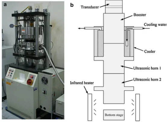
Figure 1a displays the homemade glass hot embossing apparatus, comprising a heating furnace, a compression
tester, and an ultrasonic vibration device. Table 1 lists the detailed specifications of the apparatus. The heating furnace provides a vacuum environment and heats the molds and glass with built-in infrared heaters. A servomotor drives the compression tester with feedback signals from an optical encoder and load cell. Figure 1b shows the schematic diagram of the cross-sectional structure of the upper and bottom stages in this apparatus. The upper stage is basically an ultrasonic vibration device with two horns for delivering longitudinal vibrations. To protect the device from high working temperatures, a cooling system is mounted outside the booster and ultrasonic horn 1. Infrared heaters surround the lower part of ultrasonic horn 2 and the bottom stage. 2.2 Ultrasonic horn for high temperature
The ultrasonic vibration device in this study was designed to work at 20 kHz. The frequency generator, produced by Fig. 1 a Homemade glass hot
embossing apparatus, b sche-matic diagram of the cross-sectional structure of the upper stage and bottom stage
Table 1 Specification for homemade glass hot embossing apparatus Maximum mold temperature 600°C
Maximum vacuum 2×10⁻¹Torr
Displacement accuracy 4μm
Driving resource Servomotor
Maximum load 50 kN
Ultrasonic frequency 20 kHz±500 Hz
Ultrasonic power 3.5 W
Ultrasonic vibration amplitude on booster in 25°C
King Ultrasonic Co., was set to operate at an automatic frequency tracking within the range of 20 k± 500 Hz. To avoid a frequency generator overload caused by the significant difference between the generated and resonant
frequencies, the ultrasonic horns should be designed for the appropriate tracking range. Most existing ultrasonic sys-tems are intended for use at room temperature. For glass hot embossing applications, the ultrasonic horn was operated above the glass transition temperature (For PSK-100, Tg= 390°C). Despite the automatic frequency tracking of the frequency generator, the resonant frequency would shift beyond the tracking range because of the large deviation of material properties at high temperatures. Therefore, ultra-sonic horns for high-temperature applications should be developed.
With simplified theoretical equations, the speed of a wave traveling along a one-dimensional medium is: c ¼ ffiffiffiffi E r s ð1Þ whereE and ρ are the Young’s modulus and density of the medium. The wavelength is
l ¼ c=f ð2Þ
wheref is the resonance frequency of the ultrasonic horn. In longitudinal vibrating mode, multiples of λ can be the design reference of the ultrasonic horn length. When the temperature rises in a geometrical fixed ultrasonic horn, the resonant frequency falls due to the decrease in Young’s modulus [14], therefore shifting beyond the tracking range of the frequency generator.
For this research, to increase the resonant frequency in high temperatures, the length of an existing ultrasonic horn (ultrasonic horn 2) for room temperature experimentation was reduced. The ultrasonic horn 2 material was SUS304 and the length H shown in Fig.2was modified from 53 to 50 mm. Accordingly, the maximum operating temperature successfully increased from 250°C to 450°C.
2.3 Mold and glass
The molds must resist the high temperature of the glass hot embossing process and be flexible enough to
Fig. 3 a Design size for V-groove structure and b photo-graph of V-groove mold
Fig. 2 Schematic diagram of the cross-sectional structure of ultrasonic horn 2
prevent cracks during ultrasonic vibration. Therefore, metals were chosen as the mold materials. As the upper mold, a block of stainless steel SUS304 with measure-ments of 10 mm in diameter and 10 mm in height was mounted to ultrasonic horn 2 by a grub screw, and its lower surface was polished. This study utilized both V-groove and Fresnel structures for hot embossing experi-ments. The V-groove molds were formed from stainless SUS304 by electrical discharge machining. Figure 3 displays the design size and the final mold. The Fresnel molds were formed by electroforming NiCo on an existing Fresnel structure, which was originally machined by ultra-precision machining on Ni. Figure4shows the design size and the final Fresnel mold. In Fig.4a, step heights were defined, and data from these molds and the molded glasses were measured after Fresnel structure hot embossing. The V-groove and Fresnel molds were individually fixed to the bottom stage as the lower molds. To prevent adhesion between the molds and glass during the hot embossing process, the molds were coated with PtIr. The molded glass used was PSK-100 (Sumita Optical Glass, Inc.), the Tg was 390°C, and the geometry was 7 mm in diameter
and 6.5 mm in height.
2.4 Experimental procedure
Figure 5 illustrates the experimental procedure, which progressed as follows: (1) the glass and molds were simultaneously heated to the molding temperature; (2) the upper mold began embossing the glass; (3) as embossing continued, the ultrasonic vibration was applied; (4) once embossing displacement was achieved, the ultrasonic vibration was ceased and both stages were held at their final positions for 30 s; and (5) the glass was released from the molds by lowering the lower stage and left to cool to room temperature. These procedures were all performed in a vacuum environment. Lastly, by using a 3D laser scanning microscope VK-9700, the geometries of the molded glasses were measured for further analysis.
3 Experimental result
3.1 V-groove structure hot embossing
Table 2 lists the parameters in V-groove hot embossing experiments. The molding temperatures of the upper and Fig. 4 a Design size for Fresnel
structure and b photograph of Fresnel structure mold
lower molds were measured at 435°C and 405°C, respec-tively, and in all the cases, the embossing speed was maintained at 0.5 mm/min. Each case was performed once. Figure 6 shows an example of molded glasses. The measured height from the peak to the valley of V-groove for the mold was 249μm, and Table2also lists the heights for each molded glass. The results indicate that increasing the embossing displacements from 1.5 to 2.5 mm raised the heights of the molded V-grooves from 41.2 to 89.6 μm without ultrasonic vibration. Furthermore, regarding differ-ent embossing displacemdiffer-ents, the heights were enhanced between 22.8% and 62.2% with the application of ultra-sonic vibration.
3.2 Fresnel structure hot embossing
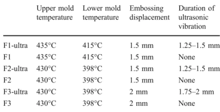
Table 3 lists the parameters in the Fresnel structure hot embossing experiments. For these cases, the embossing speed was 0.5 mm/min and each case was performed once.
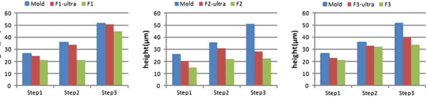
Figure 7 is an example of the molded glass, and Fig. 8 shows the step heights of the inner three steps from the Fresnel mold and all the molded glasses. In Fig. 8a, the heights from F1-ultra were significantly higher than those from F1, and its values were similar to the mold. At a lower molding temperature (Fig. 8b), the material flow was reduced, thereby lowering all the heights. The heights in F2-ultra were higher than those in F2 with the assistance of ultrasonic vibration. In F3-ultra and F3 experiments, the embossing displacements were raised, and all the structures increased in height. The results of F3-ultra demonstrate the effects of ultrasonic vibration, as shown in Fig. 8c. According to these Fresnel structure hot embossing experi-ments, the higher molding temperatures and larger emboss-ing displacement increased the molded structure heights, and with the assistance of ultrasonic vibration, these results were further enhanced, and proved the capability of the innovated ultrasonic vibration-assisted glass hot embossing process.
4 Discussion
The resonant frequency of a geometrically fixed ultrasonic horn varied with the material properties. In Eq.1, Young’s modulus has a significantly higher order than the density, and therefore, the deviation of resonant frequency caused by the change of Young’s modulus is larger than by that of the density. Thus, the density variation at a high tempera-ture is ignored in this study.
The radiation of infrared heaters was used in this design to raise the temperature of the ultrasonic horn. Traditional thermal conductive heating devices were unsuitable in this study because mounting these devices to an ultrasonic horn would cause constraints to the horn, thus changing the resonant frequency. In addition, ultrasonic vibration would damage these conductive heaters.
Table 2 Parameters in V-groove hot embossing experiments Embossing displacement Duration of ultrasonic vibration Height Deviation V1-ultra 1.5 mm 1.2–1.5 mm 50.6μm 22.8% V1 1.5 mm None 41.2μm V2-ultra 2 mm 1.75–2 mm 106.7μm 42.1% V2 2 mm None 75.1μm V3-ultra 2.5 mm 2–2.25 mm 144.4μm 62.2% V3 2.5 mm None 89.6μm
Fig. 6 Photograph of molded glass with V-groove structure
Table 3 Parameters in Fresnel hot embossing experiments Upper mold temperature Lower mold temperature Embossing displacement Duration of ultrasonic vibration F1-ultra 435°C 415°C 1.5 mm 1.25–1.5 mm F1 435°C 415°C 1.5 mm None F2-ultra 430°C 398°C 1.5 mm 1.25–1.5 mm F2 430°C 398°C 1.5 mm None F3-ultra 430°C 398°C 2 mm 1.75–2 mm F3 430°C 398°C 2 mm None
In the experimental results, the ultrasonic vibration-assisted glass hot embossing process resulted in increased heights of the molded structures in all the cases, compared to the conventional glass hot embossing process. This may be because of ultrasonic vibration, which raised the temperature locally between the glass and molds, and therefore, the glass material was softened and could easily flow into the mold cavities.
The result of the V-groove structure hot embossing experiments indicated that ultrasonic vibration enhanced the heights of the molded structures. The deviations of the heights, with and without ultrasonic vibration assistance, also increased in conjunction with the embossing displace-ments; however, through the results in Fresnel structure hot embossing experiments, as shown in Fig. 8b, c, the deviations did not increase with larger embossing displace-ments. The Fresnel structure had lower heights than the V-groove structure in the molds. Under the larger embossing
displacement of 2 mm, the structure heights of the molded glass and the mold were similar, relatively minimizing the effect of ultrasonic vibration. However, ultrasonic vibration enhanced the heights of all molded Fresnel structures.
In the experimental procedure, the glass was first embossed, and ultrasonic vibration was subsequently applied. This method prevented the glass from sliding during the initial contact of the ultrasonic vibration mold to the glass surface. In the future, the fixing method of the glass can be modified to investigate the effects of various applied timing of ultrasonic vibration in the glass hot embossing process.
5 Conclusions
This research successfully developed an ultrasonic vibra-tion device for high-temperature use by modifying horn length, and a homemade apparatus for glass hot embossing with the above ultrasonic vibration device was used to conduct ultrasonic vibration-assisted glass hot embossing experiments on PSK-100 glass. Both the V-groove and Fresnel structures were used to emboss the glasses and metals were adopted as the mold materials to endure the ultrasonic vibration during the process. The results indicated that increasing the embossing displacements raised the molded V-groove heights. By applying ultrasonic vibration, these heights were further enhanced. Regarding the Fresnel structure hot embossing experiments, the higher molding temperature and larger embossing displacement increased the molded structure heights. The molded structures were further enhanced by applying ultra-sonic vibration. In conclusion, this technology exhibits the capability to upgrade the performance of the glass hot embossing process, and has the potential to manufacture complex optical glass elements.
Fig. 7 Photograph of molded glass with Fresnel structure
Fig. 8 Heights for inner three steps from the Fresnel mold and all molded glasses a 435°C and 415°C in upper and lower molds, 1.5 mm embossing displacement b 430°C and 398°C in upper and lower
molds, 1.5 mm embossing displacement c 430°C and 398°C in upper and lower molds, 2 mm embossing displacement
Acknowledgments The authors would like to thank Metal Indus-tries Research & Development Centre and Instrument Technology Research Center, for their assistances with the mold fabrications and profile measurements of this research.
References
1. Meden-Pielinger GAA, Van de Heuvel JHP (1983) Precision pressed optical componentsmade of glass and glass suitable modeling. US Patent 4391915
2. Taniguchi Y (1999) Mold for molding optical element. US Patent 5855641
3. Firestone GC, Jain A, Yi AY (2005) Precision laboratory apparatus for high temperature compression molding of glass lenses. Rev Sci Instrum 76:063101. doi:10.1063/1.1921367
4. Yi AY, Huang C, Klocke F, Brecher C, Pongs G, Winterschladen M, Demmer A, Lange S, Bergs T, Merz M, Niehaus F (2006) Development of a compression molding process for three-dimensional tailored free-form glass optics. Appl Optics 45:6511–6518. doi:10.1364/AO.45.006511
5. Wang X, Zhou J, Gan GK, Ngoi B (2002) Theoretical and experimental studies of ultraprecision machining of brittle materials with ultrasonic vibration. Int J Adv Manuf Technol 20:99–102
6. Gan J, Wang X, Zhou M, Ngoi B, Zhong Z (2003) Ultraprecision diamond turning of glass with ultrasonic vibration. Int J Adv Manuf Technol 21:952–955
7. Shen XH, Zhang J, Xing DX, Zhao Y (2010) A study of surface roughness variation in ultrasonic vibration-assisted milling. Int J Adv Manuf Technol. doi:10.1007/s00170-011-3399-y
8. Azarhoushang B, Tawakoli T (2011) Development of a novel ultrasonic unit for grinding of ceramic matrix composites. Int J Adv Manuf Technol. doi:10.1007/s00170-011-3347-x
9. Lin CH, Chen R (2006) Ultrasonic nanoimprint lithography: a new approach to nanopatterning. J Microlith Microfab Microsyst 5:011003. doi:10.1117/1.2172992
10. Mekaru M, Noguchi T, Goto H, Takahashi M (2007) Nanoimprint lithography combined with ultrasonic vibration on polycarbonate. Jpn J Appl Phys 46:6355–6362
11. Mekaru M, Noguchi T, Goto H, Takahashi M (2008) Effect of applying ultrasonic vibration in thermal nanoimprint lithography. Microsyst Technol 14:1325–1333. doi:10.1143/JJAP.46.6355
12. Mekaru M, Noguchi T (2009) Frequency and amplitude dependences of molding accuracy in ultrasonic nanoimprint technology. J Micro-mech Microeng 19:125026. doi:10.1088/0960-1317/19/12/125026
13. Lee CH, Jung PG, Lee SM, Park SH, Shin BS, Kim JH, Hwang KY, Kim KM, Ko JS (2010) Replication of polyethylene nano-micro hierarchical structures using ultrasonic forming. J Micro-mech Microeng 20:035018. doi:10.1088/0960-1317/20/3/035018
14. Elevated temperature physical properties of stainless steels, British Stainless Steel Association. http://www.bssa.org.uk/topics.php? article=139