國 立 交 通 大 學
電信工程學系
碩 士 論 文
毫微微細胞覆蓋式正交分頻多工網路之干擾控制
Interference Control for OFDMA based overlay
Femto Networks
研究生:郭芳如
指導教授:蘇育德 博士
毫微微細胞覆蓋式正交分頻多工網路之干擾控制
Interference Control for OFDMA Based Overlay
Femto Networks
研究生:郭芳如 Student:Fang-Ju Kuo
指導教授:蘇育德博士 Advisor:Dr. Yu T. Su
國 立 交 通 大 學
電 信 工 程 學 系
碩 士 論 文
A ThesisSubmitted to Department of Communications Engineering
College of Electrical and Computer Engineering
National Chiao Tung University
in Partial Fulfillment of the Requirements
for the Degree of
Master of Science
in Communications Engineering
August 2009
Hsinchu, Taiwan, Republic of China
毫微微細胞覆蓋式正交分頻多工網路之干
擾控制
研究生:郭芳如 指導教授:蘇育德 博士
國立交通大學電信工程學系碩士班
中文摘要
隨著無線通訊容量及高速率需求的增長,催化了新興通訊傳輸技術的
發展。於室內放置毫微微細胞 (femtocell)是個增加現有無線網路通訊容量
並同時提升室內覆蓋率的可行辦法。它藉由現存的數位用戶迴路或是電纜
連接原先核心網路,可視為是種低功率的無線網路橋接器。
雖然目前已有寬頻分碼多工(WCDMA) 系統之毫微微細胞相關產品
上市,但由於無法有效解決與原始的網路之間相互干擾的問題,普及度並
不高。本文的主旨則在研究於第四代的通訊正交分頻多工(OFDMA)系統內
佈建毫微微蜂巢網路之關鍵技術課題:即網路內及網路間的干擾消除與控
制。因為干擾的形成主要來自於新(毫微微細胞)、舊(現存)網路之頻
率與功率的規劃、統籌各自為政。我們所提的方案乃是從問題的根本著
手,透過適當的資源(次載波、傳輸功率)分配將網路內及網路間之干擾
控制在可容許的範圍。本文集中於下傳(Downlink)情境之同頻干擾控制,
鄰頻干擾需藉由新舊網路之同步及輸出信號之旁波帶規範來解決。我們證
明了,藉由適當的系統資源分配不但可以大大降低同頻干擾、提升網路容
量與資源使用效益,並可提高毫微微蜂巢網路的建置效益。
Interference Control for OFDMA Based Overlay
Femto Networks
Student : Fang-Ju Kuo Advisor : Yu T. Su
Department of Communications Engineering National Chiao Tung University
Abstract
Increasing demand for higher wireless system capacity and the need of high speed residential areas has catalyzed several new transmission techniques and network archi-tecture. Deploying femtocells in the house is a candidate solution to solve the capacity problem. Femtocells are low-power wireless access points that operate in licensed spec-trum to connect standard mobile devices to a mobile operator’s network using residential DSL, cable broadband or wireless connections.
Although some femto-related products are available in the market, they were designed for use in 3G networks and the performance seems to be less than satisfactory. The most critical physical layer design issue in a two-tier (femtocells overlaying existing marco-cells) femtocell network is interference control and management, i.e., to contain femto-to-macro, femto-to-femto and macro-to-femto interference to within specified bounds such that the network capacity/throughput is maximized with fixed femto transmit power.
In this study, we focus on OFDMA-based 4G networks and investigate the issue of interference management. We provide a feasible solution by proposing downlink re-source (power and subcarriers) allocation algorithm in an OFDMA-based overlay femto (femto-macro coexisting) network. It is shown that through proper resource allocation,
interference in an OFDMA network, as measured by signal-to-noise-plus-interference ra-tios at the active user terminals, can be controlled to within the tolerable range while the network still maintaining outstanding spectral efficiency (capacity) performance.
誌 謝
對於論文得以順利完成,首先感謝我的指導教授 蘇育德博士。老師
的諄諄教誨不只使我於通訊領域上有更深入的了解,生活上的指導也令我
受益匪淺。感謝口試委員陳伯寧教授、沈文和教授、楊谷章教授以及陳永
芳教授給予的寶貴意見,以補足這分論文的缺失與不足之處。另外,由衷
感謝實驗室學長姐、同學及學弟妹在這兩年內的幫忙與鼓勵。
最後,感謝一直在背後默默支持我的家人,他們的關心與鼓勵是我帶
給了我無形的動力,僅獻上此論文,以代表我最深的敬意。
Contents
Chinese Abstract i
English Abstract ii
Acknowledgements iv
Contents v
List of Figures vii
List of Tables ix
1 Introduction 1
2 Scenario and Problem Formulation 5
2.1 Scenario and Assumptions . . . 5
2.2 Problem Formulation . . . 6
3 Downlink Resource Allocation for Single Overlay Femtocell 11 3.1 Subcarrier Assignment . . . 11
3.1.1 Equivalent gain based subcarrier assignment . . . 11
3.1.2 Virtual maximum SINR based subcarrier assignment . . . 13
3.1.3 Subcarrier assignment without fairness consideration . . . 14
3.2 Power Allocation without Femtocell SINR Constraints . . . 14
3.2.2 Power allocation using iterative water-filling . . . 17
3.3 Power Allocation with Femtocell SINR Constraints . . . 24
4 Downlink Resource Allocation for Multiple Overlay Femtocells 27 4.1 Scenario and Problem Formulation . . . 27
4.1.1 Multiple overlay femtocells . . . 27
4.1.2 Problem formulation . . . 28
4.2 Downlink Resource Allocation . . . 29
4.2.1 Scheme A: Disjoint femtocell subcarrier assignment . . . 29
4.2.2 Scheme B: Subcarrier Assignment with Fully Frequency Reuse . . 31
5 Numerical Results and Discussions 32 5.1 Femtocell Power Allocation without SINR Constraints . . . 33
5.2 Femtocell Power Allocation with SINR Constraints . . . 36
5.3 Comparison of Femtocell Subcarrier Assignment Schemes . . . 39
5.4 Resource Allocation for Multiple Femtocells . . . 42
6 Conclusion 48
Bibliography 49
List of Figures
1.1 Typical femtocell deployment scenario. . . 2
2.1 A two-tier OFDMA cellular network that consists of one mBS, one fBS, several mMS, and several fMSs. . . 5
2.2 Interference scenario. . . 7
3.1 Block diagram of the resource allocation scheme. . . 11
3.2 Flow chart of iterative equal power allocation algorithm. . . 16
3.3 Illustration of water-filling interpretation. . . 19
3.4 Flow chart of Rate-Adaptive water filling algorithm. . . 21
3.5 Flow chart of iterative water filling power allocation algorithm. . . 23
3.6 Illustration of water-filling with power lower bound. . . 24
3.7 Illustration of iterative water-filling with power lower bound. . . 26
4.1 A two-tier OFDMA cellular network that consists of one mBS, multiple fBSs, several mMSs, and several fMSs. . . 28
5.1 Macrocell bandwidth efficiency versus mMS’ SINR constraints with dif-ferent power allocation methods in the scenario of 1 fMS. . . 34
5.2 Femtocell bandwidth efficiency versus mMS’ SINR constraints with dif-ferent power allocation methods in the scenario of 1 fMS. . . 35
5.3 Total bandwidth efficiency versus mMS’ SINR constraints with different power allocation methods in the scenario of 1 fMS. . . 35
5.4 Femtocell bandwidth efficiency versus mMS’ SINR constraints with dif-ferent power allocation methods considering fMS’ SINR constraints in the scenario of 1 fMS. . . 37 5.5 Femtocell bandwidth efficiency versus mMS’ SINR constraints with
dif-ferent fMS’ SINR constraints using iterative water-filling power allocation methods in the scenario of 1 fMS. . . 38 5.6 Femtocell bandwidth efficiency versus mMS’ SINR constraints with
dif-ferent subcarrier assignment methods in the scenario of 3 fMS. . . 40 5.7 Femtocell bandwidth relative efficiency versus mMS’ SINR constraints
with different subcarrier assignment methods in the scenario of 3 fMS. . . 41 5.8 Macrocell bandwidth efficiency versus mMS’ SINR constraints with
dif-ferent resource allocation methods in the scenario of multiple fBSs with 1 fMS. . . 43 5.9 Femtocell bandwidth efficiency versus mMS’ SINR constraints with
dif-ferent resource allocation methods in the scenario of multiple fBSs with 1 fMS. . . 43 5.10 Total bandwidth efficiency versus mMS’ SINR constraints with different
resource allocation methods in the scenario of multiple fBSs with 1 fMS. 44 5.11 Macrocell bandwidth efficiency versus mMS’ SINR constraints with
dif-ferent resource allocation methods in the scenario of multiple fBSs with random amount of fMSs. . . 45 5.12 Femtocell bandwidth efficiency versus mMS’ SINR constraints with
dif-ferent resource allocation methods in the scenario of multiple fBSs with random amount of fMSs. . . 46 5.13 Total bandwidth efficiency versus mMS’ SINR constraints with different
resource allocation methods in the scenario of multiple fBSs with random amount of fMSs. . . 47
List of Tables
3.1 Subcarrier allocation based on equivalent gains. . . 12 3.2 Subcarrier allocation based on virtual maximum SINR. . . 14 3.3 Subcarrier allocation based on equivalent gains regardless of fairness. . . 14 4.1 Subcarrier allocation based on equivalent gains. . . 30 5.1 Simulation Parameters . . . 32 5.2 Modulation and coding scheme (MCS) in the Downlink . . . 33
Chapter 1
Introduction
In recent years, the demand for higher data rates in wireless networks is dramati-cally increased. The growth in telecommunications capacity requirement has promoted the development and design of new cellular standards such as WiMAX (802.16e), the Third Generation Partnership Project’s (3GPP’s), High Speed Packet Access (HSPA), 3GPP2’s EVDO and UMB standards, and LTE standards. Besides, extending coverage into residential areas is one of the biggest challenges for current mobile communication networks. Since it is extremely expensive to serve the indoor users with large service de-mands, a significant interest within the telecommunications industry has recently focused on how to provide service for indoor users in a cost-efficient way. Deploying Femtocells or home base stations in the house is a solution to increase the capacity requirement and to overcome coverage problem for indoor users while reducing operating expenses [1].
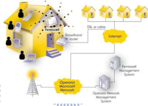
A femtocell consists of a cellular access point that connect to a service provider using residential DSL (Digital Subscriber Line) or cable broadband connections and some femto mobile stations, as shown in Fig. 1.1 [1]. The access point is also referred to as the femto base station (fBS) which is a low-power base stations designed for indoor usage. Users deploying femtocells can provide improved indoor coverage and increase the capacity. By installing a home base station, phone battery could be saved because wireless radio only propagates in short distance from the user device to the home base
station. More specifically, the benefits of femto cell networks can be explained from two aspects. From the operator’s viewpoint, the benefits include (1) reduce backhaul capacity requirements; (2) increase wireless capacity; (3) reduce coverage holes and create new converged services. From the customer’s viewpoint, the benefits includes (1) superior in-building coverage and quality without change in phones; and (2) one number and one phone for location specific pricing.
Figure 1.1: Typical femtocell deployment scenario.
Although the potential benefits of femtocells technology have attracted considerable attention, it is still not a matured one. Several key aspects of femtocells technology still need further studies before it becomes a marketable commercial commodity [2]. For example, power control, interference avoidance, access methods, frequency band alloca-tion, security, synchronizaalloca-tion, and efficient hand-off mechanisms, to name a few, are all important issues. Furthermore, some serious problems take place while femtocells coexist with macrocells. Femtocells operating on a dedicated and separated frequency band could overcome the interference phenomenon from macrocells to femtocells and vice versa. A hybrid efficient frequency assignment technique is proposed for femtocells
[3]. Although femtocells use different frequency band from macrocells is a possible solu-tion to interference avoidance, however, it will reduce spectral efficiency usage. Special attention should be paid while co-channel deployments are concerned. In [4], perfor-mance of co-channel deployment of femtocells with macrocells was provided. Cross-tier co-channel interference between femtocells and macrocells will be reduced by using fre-quency reuse with pilot sensing [5]. Dynamic frefre-quency planning (DFP) is utilized to avoid interference between femtocells and macrocells [6]. In addition, Femtocells must have the ability to auto-configure parameters [7] [8]. Examples of the parameters that need to be configured automatically include power, Cell-ID, neighbor list, location, etc. Power configuration is discussed most [9] [10] .
Due to its robustness against frequency selective fading and its flexibility in radio resource allocation for meeting various QoS requirements, the Orthogonal Frequency Division Multiple Access (OFDMA) has been adopted or considered as a candidate multiple access scheme for future wide area broadband wireless networks that support a wide variety of services. OFDMA exploits multi-user diversity in time-varying frequency-selective fading channels by assigning a subcarrier to the MS with the best channel gain and by scheduling the transmission of user data opportunistically.
Though many of the major issues concerning femtocells technologies have been ad-dressed, there are few research reports that consider the design of femtocells in an OFDMA network. The most critical issue associated with any femtocell system design is that of interference management, i.e., one needs to ensure that the macro-to-femto, femto-to-marcor, and femto-to-femto interference is contained such that the signal-to-noise-plus-interference ratio at each receive site satisfies the predetermined threshold. As the magnitude of interference in an OFDMA network is a function of the transmit power and link (subcarrier) gain (attenuation), interference management must be solved by proper power allocation and frequency band or subcarrier partition/assignment. In this thesis, we formulate the interference management problem as a resource allocation
one. We shall consider the downlink of an OFDMA-based femtocell system only and propose effective resource allocation schemes for a femto BS.
The rest of this thesis is organized as follows. In following chapter, we present the system model and formulate the associated resource allocation problem with . In chapter 3, we proposed algorithms to solve the problem. The resource allocation problem is extended to the case for multiple femtocell base stations in chapter 4. Finally, simulation results are provided in chapter 5.
Chapter 2
Scenario and Problem Formulation
2.1
Scenario and Assumptions
A two-tier orthogonal frequency division multiple access (OFDMA) cellular network is considered in this study.
Figure 2.1: A two-tier OFDMA cellular network that consists of one mBS, one fBS, several mMS, and several fMSs.
The network layout under investigation is illustrated in Fig. 2.1. We first discuss the simple case where there is only one macrocell base station (mBS) and one femtocell base station (fBS). The numbers of macrocell mobile station (mMS) and femtocell mobile station (fMS) are K and L respectively.
The K mMSs are located randomly within one of the macrocell’s sector with each mMS given a disjoint subset of the N subcarriers. The resource allocation scheme of the macrocell is based on that proposed in [11]. On the other hand, the fBS is located ran-domly within the corresponding macrocell’s sector while fMSs are uniformly distributed within the femtocell boundary. The femtocell network works on the premise of not inter-fering existing macrocell subscribers. It is assumed that the fBS could acquire location information of mMS’ through backhal connection.
2.2
Problem Formulation
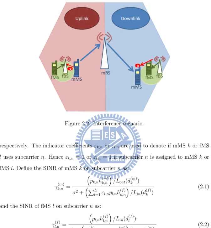
The radio interference between femtocell and macrocell users is or primary concern when macrocell and femtocell share the same spectrum. Fig. 2.2 illustrates interference problems to macrocell and femtocell users [6]. A far dwonlink mMS could be jammed due to the presence of a closer downlink femtocell user who is using the same frequency band. On the other side, a uplink femtocell user could be interfered by nearby co-channel mMSs. In this study, we focus on the downlink interference issue and try to contain such cross-tier interference through downlink subcarriers assignment and power control. The design goal is formulated as an optimization problem such that the overall system capacity is maximized while the co-channel interference is within the tolerance limits.
We assume that signals received by user terminals experience independent fadings and denote by h(m)k,n and pk,n the channel (link) gain of and the power allocated to mMS
k on subcarrier n. Similarly, the channel gain and power of fMS l on subcarrier n are represented by h(f )l,n and pl,n respectively. Then the interference on mMS and fMS
can be expressed as PLl=1³εl,npl,nh(f )k,n ´ /Lin(d(f )k ) and PK k=1 ³ εk,npk,nh(m)l,n ´ /Lout(d(m)l ),
Figure 2.2: Interference scenario.
respectively. The indicator coefficients εk,n or εl,n are used to denote if mMS k or fMS
l uses subcarrier n. Hence εk,n = 1 or εl,n = 1 if subcarrier n is assigned to mMS k or
fMS l. Define the SINR of mMS k on subcarrier n as:
γk,n(m) = ³ pk,nh(m)k,n ´ /Lout(d(m)k ) σ2+³PL l=1εl,npl,nh (f ) k,n ´ /Lin(d (f ) k ) (2.1)
and the SINR of fMS l on subcarrier n as:
γl,n(f ) = ³ pl,nh(f )l,n ´ /Lin(d(f )l ) σ2+³PK k=1εk,npk,nh (m) l,n ´ /Lout(d (m) l ) (2.2)
where Loutand Linare the functions of outdoor and indoor path loss, path loss values
depend on distances. d(m)k and d(f )k are the distances from the mMS k to the mBS and the fBS. d(m)l / d(f )l denotes the distance between fMS l and the macrocell/femtocell BS. σ2 is additive white Gaussian noise (AWGN).
For an implementable system operating at low enough probability of symbo error, it is necessary to introduce a SNR gap, denoted by Γ. The gap is a function of the
permissible probability of bit error rate (BER) and the encoding system of interest [12]. We may write rl,n(f ) = log2(1 + γ (f ) l,n Γ ) = log2(1 + pl,ngl,n) (2.3) where Γ = − ln(5BER)/1.5 is the constant SNR gap and gl,n is the equivalent link gain
defined by gl,n = (h(f )l,n)/Lin(d(f )l ) σ2+³PK k=1εk,npk,nh(m)l,n ´ /Lout(d(m)l ) (2.4) The problem of downlink resource allocation that maximizes a femtocell’s total band-width efficiency while satisfying limited interference constraints is formulated as
(p.1) max εl,npl,n 1 N N X n=1 L X l=1 εl,n· log2 ³ 1 + pl,ngl,n Γ ´ (2.5) subject to: pl,n ≥ 0 ∀l, n (2.6) L X l=1 N X n=1 εl,npl,n ≤ P (f ) total (2.7) γk,n(m) Γ ≥ γ (m) th ∀εk,n = 1 (2.8) εl,n ∈ {0, 1} ∀l, n (2.9) L X l=1 εl,n = 1 ∀n (2.10)
where p(f )total is the transmit power constraint of the fBS. For the downlink case, all signals are transmitted from the same base station, hence the total transmitter power will be considered (2.7).The power constraints of femtocell on each subcarrier are given in (2.6). Constraint (2.8) represents the QoS requirements of mMS’, γth(m) are SINR thresholds of mMs’. The indicators εl,n in (2.9) (2.10) is inserted to ensure that each
subcarrier can be assigned to one user only.
γk,n(m) Γ ≥ γ (m) th ³ pk,nh(m)k,n/Γ ´ /Lout(d(m)k ) σ2+³PL l=1εl,npl,nh (f ) k,n ´ /Lin(d (f ) k ) ≥ γth(m) L X l=1 εl,npl,n ≤ 1 h(f )k,n/Lin(d (f ) k ) ³ Pk,nh (m) k,n/Γ ´ /Lout(d (m) k ) γth(m) − σ 2
Since one subcarrier can only serve one fMS (2.10), the peak femto power constraint on subcarrier n can be rewritten as:
pupper,n = max 0, 1 h(f )k,n/Lin(d (f ) k ) ³ Pk,nh(m)k,n/Γ ´ /Lout(d(m)k ) γth(m) − σ 2 (2.11)
The problem formulated above (p.1) only guarantees SINR value of mMS’. Another downlink resource allocation problem is addressed by considering the Qos of both the mMS’ and the fMS’ in terms of their received SINR values.
(p.2) max εl,npl,n 1 N N X n=1 L X l=1 εl,n· log2 ³ 1 + pl,ngl,n Γ ´ subject to: pl,n ≥ 0 ∀l, n L X l=1 N X n=1 εl,npl,n ≤ Ptotal(f ) γk,n(m) Γ ≥ γ (m) th ∀εk,n = 1 γl,n(f ) Γ ≥ γ (f ) th ∀εl,n = 1 (2.12) εl,n ∈ {0, 1} ∀l, n L X l=1 εl,n = 1 ∀n
(2.12) is inserted to make sure that fMS’ SINR on every subcarrier is above a certain threshold. Similar to (2.11), the power lower bound on each subcarrier can be derived from fMS SINR constraint (2.12):
γl,n(f ) Γ ≥ γ (f ) th ³ pl,nh (f ) l,n/Γ ´ /Lin(d (f ) l ) σ2+³PK k=1εk,npk,nh(m)l,n ´ /Lout(d(m)l ) ≥ γth(f ) pl,n ≥ 1 h(f )l,n ( γth(f ) " σ2+ Ã K X k=1 εk,npk,nh(m)l,n ! /Lout(d(m)l ) # Lin(d(f )l ) · Γ )
The power lower bound on each subcarrier n:
plower,n = 1 h(f )l,n ( γth(f ) " σ2+ Ã K X k=1 εk,npk,nh (m) l,n ! /Lout(d (m) l ) # Lin(d (f ) l ) · Γ ) (2.13)
Chapter 3
Downlink Resource Allocation for
Single Overlay Femtocell
This chapter considers the scenario when there is only one overlay femtocell within a marco-cell. We present resource allocation schemes for downlink femtocell base station. The algorithm is designed to maximize the total bandwidth efficiency while meeting the co-channel interference constraints. The block diagram of the proposed scheme is shown below. Details of the resource allocation scheme are discussed in the following sections.
Figure 3.1: Block diagram of the resource allocation scheme.
3.1
Subcarrier Assignment
For the scenario of multiple fMS’, subcarrier assignment should be performed firstly.
First, we re-indexing the N subcarriers based on the descending order of their max-imum equivalent gain gl,n. Our algorithm attempts to assign a subcarrier to the user
with the best equivalent gain according to the new ordering. Meanwhile, fairness among users should be taken into account. A simple fairness solution is to require that the number of subcarriers allocated to each user be the same for all users.
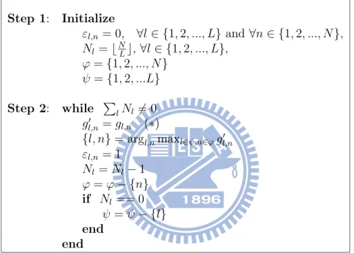
The algorithm is described below. Step 1: Initialize εl,n = 0, ∀l ∈ {1, 2, ..., L} and ∀n ∈ {1, 2, ..., N }, Nl= bNLc, ∀l ∈ {1, 2, ..., L}, ϕ = {1, 2, ..., N } ψ = {1, 2, ...L} Step 2: while PlNl6= 0 g0 l,n = gl,n (∗) {l, n} = argl,nmaxl∈ψ,n∈ϕg0l,n εl,n = 1 Nl= Nl− 1 ϕ = ϕ − {n} if Nl == 0 ψ = ψ − {l} end end
Table 3.1: Subcarrier allocation based on equivalent gains.
where
εl,n indicator, as in (2.9). εl,n = 1 if subcarrier n is assigned to fMS l,
Nl number of subcarrier assigned to fMS l,
ϕ set of unallocated subcarriers,
ψ set of fMS’ without obtaining sufficient subcarriers gl,n equivalent gain of fMS l on subcarrier n
Parameters are initialized at step 1. Step 2 iterates until all the fMS acquire suffi-cient subcarriers. In each time of iteration, the maximum equivalent gain is found and the corresponding subcarrier is assigned. Since each subcarrier can be assigned to one user only (2.10), we exclude the assigned subcarrier from unallocated subcarriers set. Under fairness consideration, fMS stops allocating subcarriers after it obtains sufficient subcarriers.
3.1.2
Virtual maximum SINR based subcarrier assignment
It is not necessarily true that allocating a subcarrier to the user with the best equiv-alent gain gives better (or the best) bandwidth efficiency. Note that (2.5) reveals that bandwidth efficiency is not only a function of the equivalent gain gl,n but also depends
on the transmit power pl,n , which is bounded by (2.11). We define virtual maximum
SINR on each subcarrier as gl,n · pupper,n and modify the algorithm given in subsection
3.1.1 by replacing the equation marked as (*) by g0
l,n = gl,n· pupper,n. Step 1: Initialize εl,n = 0, ∀l ∈ {1, 2, ..., L} and ∀n ∈ {1, 2, ..., N }, Nl= bNLc, ∀l ∈ {1, 2, ..., L}, ϕ = {1, 2, ..., N } ψ = {1, 2, ...L} Step 2: while PlNl6= 0 g0 l,n = gl,n· pupper,n {l, n} = argl,nmaxl∈ψ,n∈ϕg0l,n εl,n = 1 Nl= Nl− 1 ϕ = ϕ − {n} if Nl == 0 ψ = ψ − {l} end end
Table 3.2: Subcarrier allocation based on virtual maximum SINR.
3.1.3
Subcarrier assignment without fairness consideration
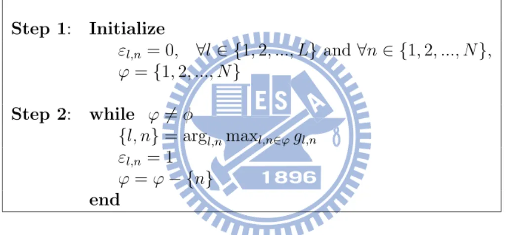
The algorithms proposed in subsections 3.1.1 and 3.1.2 take fairness into consid-eration. Subcarriers are thus distributed equally among all fMSs. If we ignore the fairness concern in assigning subcarriers, the total bandwidth efficiency could be im-proved. Without subcarrier number constraint on each fMS, it is unnecessary to take account of the factor pupper,n since power upper bounds are independent of fMSs.
Step 1: Initialize εl,n = 0, ∀l ∈ {1, 2, ..., L} and ∀n ∈ {1, 2, ..., N }, ϕ = {1, 2, ..., N } Step 2: while ϕ 6= φ {l, n} = argl,nmaxl,n∈ϕgl,n εl,n = 1 ϕ = ϕ − {n} end
Table 3.3: Subcarrier allocation based on equivalent gains regardless of fairness.
3.2
Power Allocation without Femtocell SINR
Con-straints
For a fixed subcarriers assignment, the resource allocation problem (P.1) is reduced to the simpler problem of power allocation among multiple users. The issue of down-link power allocation with femtocell users’ SINR constraints (p.2) is addressed in the following section.
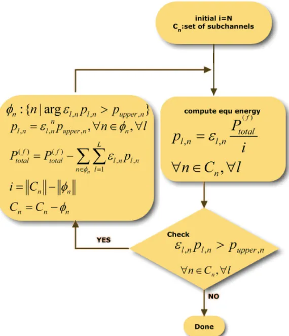
The flow chart of iterative equal power allocation algorithm is shown below. Param-eters are defined as:
Cn set of subcarriers that the allocated power is below the corresponding upper bound ,
φn set of subcarriers that the allocated power is set to the upper bound l,
i number of subcarriers that the allocated power is below the corresponding upper bound, k k denotes number of elements in the set
Firstly, all the usable downlink power of fBS’ is equally distributed among all avail-able subcarriers. We then check if this power on subcarrier n exceeds its corresponding upper bound ppupper,n. The power allocated to subcarrier n is set to pupper,n if exceeded.
The excess power can be reallocated to other subcarriers. This process continues until either the allocated power for each subcarrier satisfies the corresponding upper limit (2.11) or all the fBS’ usable power has been exhausted.
3.2.2
Power allocation using iterative water-filling
¥ Conventional Water-filling Algorithm
The water-filling algorithm is proposed to deal with a constrained optimization prob-lem that maximize the bit rate R for the entire multichannel transmission system through an optimal sharing of the total transmit power P between the N subchannels, subject to the constraint that P is maintained constant [12]. The problem is formulated as:
max 1 2N N X n=1 log2 ³ 1 + gnpn Γ ´ (3.1) subject to: N X n=1 Pn = P (3.2)
where gn is the equivalent gain of subchannel n.
To solve this optimization problem, the method of Lagrange multipliers is applied [13]. J = 1 2N N X n=1 log2 µ 1 + gnPn Γ ¶ + λ Ã P − N X n=1 Pn ! = log2e 2N N X n=1 ln µ 1 + gnPn Γ ¶ + λ Ã P − N X n=1 Pn !
where λ is the Lagrange multiplier. Differentiation J with respect to Pn, and solve
∂J ∂Pn = 0 ∂J ∂Pn = 1 2N log2e · gn Γ 1 + gnPn Γ − λ = 0 let K = 1 2N · log2e λ we have Pn+ Γ gn = K (3.3)
From equation (3.3), we can make a conclusion that the sum of the transmit power Pn
and Γ
gn must be maintained constant K for each subchannel. Hence, equations (3.2) and
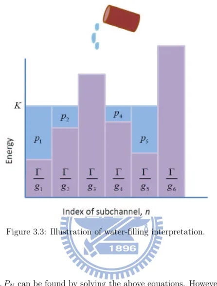
(3.3) should be satisfied in solving the described problem. Fig. 3.3 gives an appropriate interpretation of the optimum solution. The constrained optimization problem can be thought as pouring fixed amount of water (standing for total available transmit power, (3.2) into a container with different depth (representing the different ratio Γ/gn).
In mathematical view point, we may obtain the solution by solving the set of linear equations: P1+ P2+ . . . + PN = P P1− K = − Γ g1 P2− K = − Γ g2 ... ... PN − K = − Γ gN (3.4) In matrix form, the equations become
1 1 . . . 1 0 1 0 . . . 0 −1 0 1 . . . 0 −1 ... ... ... ... 0 0 . . . 1 −1 P1 P1 ... PN K = P −gΓ 1 −Γ g2 ... − Γ
Figure 3.3: Illustration of water-filling interpretation.
K, P1, P2, ..., PN can be found by solving the above equations. However, some of the
Ps might be negative. The negative Ps are discarded since power can not be negative.
After negative Ps are excluded, the water level of other subchannels should be reduced
accordingly. Those negative Ps are removed from the set of equation and the remaining
Ps are solved again.
¥ Practical Implementation Based on the Water-filling Concept
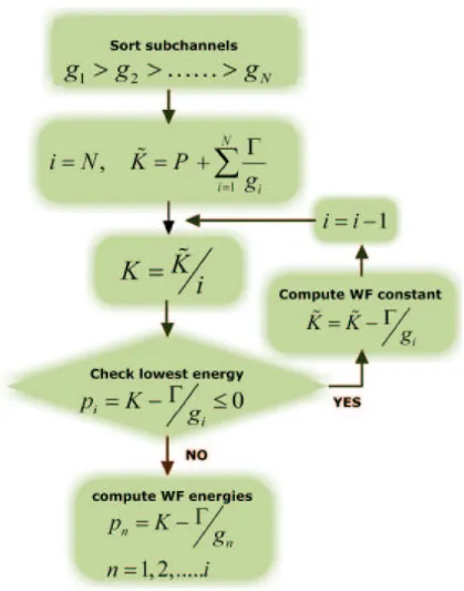
A rate-adaptive water-filling algorithm was suggested in [14] to deal with negative Ps. Summing the last N equations of (3.4) we have
K = 1 N " P + Γ · N X n=1 1 gn # (3.5)
and
Pn = K −
Γ gn
, ∀n (3.6)
If one or more of Pn is negative, the most negative one is eliminated and the
cor-responding gn term is also removed. Equations (3.5) and (3.6) are solved again with
N → N − 1. For express convenience, gn is preordered in descending order. That is,
1/gn will increase progressively. Equation (3.5) at the ith step becomes
K = 1 N − i " P + Γ · N −i X n=1 1 gn # (3.7) where i is the value that does not cause a negative power on Pi at the first time. And
the power loaded on subchannel n is
Pn= K −
Γ gn
∀n = 1, ..., N − i (3.8) The flow chart of Rate-Adaptive water filling algorithm is illustrated in Fig. 3.4. The minimum non-positive power is found step by step. It may not be an efficient way. We will introduce a bisection method to improve the speed of convergence later.
¥ An Iterative Water-filling Algorithm
Although in reality there is a peak power constraint on every subcarrier, equation (2.11), we shall not consider this constraint to begin with. Solving the problem with the individual power upper bound on each subcarrier and total peak power constraint in two steps. In the first step, we solve the problem to obtain the required optimal total bandwidth efficiency and then check if the solution meets the peak power constraint on every subcarrier. The problem is solved if the constraint is satisfied; otherwise the problem does not have an admissible solution and one is forced to go to step 2. In step 2, power loaded on the subcarriers with more power than its upper bound will be set to the value of its upper limit, and the remaining power is reallocated to other subcarriers. The final solution is obtained by an iterative process.
The flow chart, Fig. 3.5, describes our power allocation algorithm. The green blocks in the flow chart represents a practical implementation based on the water-filling concept. We use bisection method to find the minimum non-positive power (2.6). After water-filling power allocation is carried out, power on each subcarrier should be checked if it exceeds the allowed power upper bound. Similar to the algorithm described in Section 3.2.1, the iterative procedure continues until either the power given to each subcarrier meets its upper bound requirement or all the fBS’ available power has been distributed.
3.3
Power Allocation with Femtocell SINR Constraints
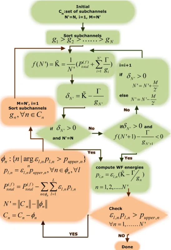
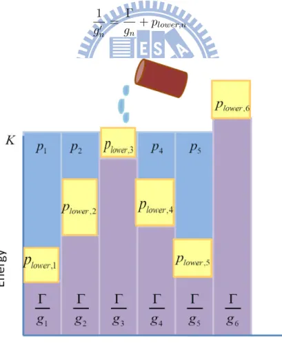
In this section, femtocell users’ SINR constraints are taken into consideration in the course of power allocation. We modify the algorithm mentioned in the previous section in order to satisfy the power lower bound, equation (2.13). We pre-allocate power on each subcarrier with the corresponding power lower bound, and execute iterative water-filling algorithm with the remaining available power. Before implement the iterative filling algorithm, we make change in the ”depth” of the ”container” in water-filling algorithm, as shown in Fig. 3.6:
1 g0 n = Γ gn + plower,n (3.9)
Similar to traditional water-filling algorithm, sort 1/g0
nin increasing order firstly, and
then carry out the following operations:
Pava = Ptotal(f ) −
N0
X
n=1
plower,n (3.10)
where plower,n is the corresponding power lower bound.
K = 1 N " Pava+ N0 X n=1 1 g0 n # (3.11) and Pn= K − 1 g0 n + plower,n , ∀n (3.12)
The same as iterative water-filling algorithm, we inspect power on each subcarrier and find if it is beyond the peak bound. Iteration continues until a reasonable solution is found. Detail of the algorithm is illustrated in Fig. 3.7
Chapter 4
Downlink Resource Allocation for
Multiple Overlay Femtocells
In this chapter, we extend the problem in previous chapters to a scenario of multiple femtocell base stations. In section 4.1, we reformulate a downlink resource allocation problem and describe the system model of concern. Different solutions to the problem are presented in section 4.2.
4.1
Scenario and Problem Formulation
4.1.1
Multiple overlay femtocells
An environment of multiple fBS’ is introduced in this section. Following the scenario mentioned before, there are several mMSs in the one mBS but multiple fBSs and fMSs lie in the coverage of mBS. For simulation feasibility, we define a ”femtocell region” that all the fBSs concentrated in this area. And the femtocell region is randomly distributed in the sector of mBS. Figure 4.1 shows the deployment of the mBS, mMSs, fBSs, and fMSs.
Figure 4.1: A two-tier OFDMA cellular network that consists of one mBS, multiple fBSs, several mMSs, and several fMSs.
4.1.2
Problem formulation
If multiple fBSs are considered, interference exists among femtocells. We modify the problem (p.1) and extend it as one suitable for the scenario of multiple fBSs:
(p.3) max εm,l,npm,l,n 1 N M X m=1 N X n=1 Lm X l=1 εm,l,n· log2 ³ 1 + pm,l,ngm,l,n Γ ´ (4.1)
subject to: pm,l,n ≥ 0 ∀m, l, n (4.2) Lm X l=1 N X n=1 εm,l,npm,l,n ≤ Ptotal,m(f ) ∀m (4.3) γk,n(m) Γ ≥ γ (m) th ∀εk,n= 1 (4.4) εm,l,n ∈ {0, 1} ∀m, l, n (4.5) Lm X l=1 εl,n = 1 ∀m, n (4.6)
where εm,l,n = 1 if user l of fBS m uses subcarrier n and power loaded on it is denoted
as pm,l,n.Lm represents the fMS’ number in fBS m. gm,l,nis equivalent gain on subcarrier
n of fMS l in the coverage of fBS m, defined as:
gm,l,n= (h(f )m,l,n)/Lin(d(f )m,l) σ2+ Ã K X k=1 εk,npk,nh (m) m,l,n ! /Lout(d (m) m,l) | {z }
interference from macrocell
+ M X m0=1,m06=m L0 m X l=1 εm0,l,npm0,l,nh(f )m,l,n L(d(f )m0,l) | {z }
interference from other femtocells
(4.7)
Constraint (4.2) reveals that power must be non-negative. The total downlink power of any fBS is limited, equation (4.3). (4.5) polices that each subcarrier can only be assigned once within anyone fBS.
4.2
Downlink Resource Allocation
4.2.1
Scheme A: Disjoint femtocell subcarrier assignment
In this method, since all the subcarrier can only be utilized once, subcarrier assign-ment among fBSs is carried out in the first place. The problem of downlink resource allocation for multiple fBSs transforms into independent resource allocation problems.
Unfinished procedure is performed by individual fBS according to the subcarriers belong to it. Table 4.1 presents detail of the subcarrier assignment algorithm among fBSs.
Step 1: Initialize Im,n = 0, ∀m ∈ {1, 2, ..., M } and ∀n ∈ {1, 2, ..., N }, Nm = bPMLm m0=1Lm0 · N c, ∀l ∈ {1, 2, ..., L}, ϕ = {1, 2, ..., N } ψ = {1, 2, ...M } Step 2: while PmNm 6= 0 g0 m,n = maxlmgm,lm,n {m, n} = argm,nmaxm∈ψ,n∈ϕgm,n0 Im,n = 1 Nm = Nm− 1 ϕ = ϕ − {n} if Nm == 0 ψ = ψ − {m} end end Step 3: while kϕk 6= 0 if kψk = 0 ψ = {1, 2, ...M } end {m, n} = argm,nmaxm∈ψ,n∈ϕgm,n0 Im,n = 1 ϕ = ϕ − {n} ψ = ψ − {m} end
Im,n indicator, Im,n = 1 if subcarrier n is assigned to fBS m,
Nm number of subcarrier assigned to fBS m,
Lm number of fMS’ belong to fBS m,
ϕ set of unallocated subcarriers, ψ set of fBS’,
gm,lm,n equivalent gain of fMS lm of fBS m on subcarrier n
4.2.2
Scheme B: Subcarrier Assignment with Fully Frequency
Reuse
Unlike the way asserted in the previous section, all the subcarriers can be utilized by any arbitrary fBS in method B. Under that situation, the frequency diversity will be prompted although interference must occur among different femtocells. Every fBS executes resource allocation process without considering effect upon other femtocells.
Chapter 5
Numerical Results and Discussions
In this chapter we revisit the scenarios discussed in Chapter 2 and examine the numerical performance of our algorithms when applied to solve the femtocell resource allocation problems. We firstly discussed the scenario of only one fBS in section 5.1, 5.2, and 5.3. And then we focus on the problem addressed in chapter 4. The parameters of the simulation are shown in table 5.1.
Table 5.2 lists the modulation and coding scheme (MCS), their required Signal to Noise Ratio (SNR) and β values for downlink. The β value is defined in [15].
Table 5.2: Modulation and coding scheme (MCS) in the Downlink
5.1
Femtocell Power Allocation without SINR
Con-straints
A simple scenario that there is only 1 fMS is discussed in Fig. 5.1 and Fig. 5.2. Subcarrier assignment is omitted since all the subcarriers can be allocated to the only 1 fMS. Fig. 5.1 shows the total bandwidth efficiency of macrocell network versus different SINR constraints, in (2.8), on each subcarrier for mMS. Similarly, Fig. 5.2 is the results of total bandwidth efficiency of femtocell network versus different macrocell users’ SINR constraints. Different power allocation methods are compared in the figures. In Fig. 5.1, the line denoted as macro is the bandwidth efficiency without deploying a femtocell network. The lines marked ”iterative equ” is the result of using power allocation method mentioned in 3.2.1. The lines marked ”interative water” is the outcome of utilizing the algorithm proposed in 3.2.2. And the lines marked ”one water” and ”one equal”
inves-tigate the results that only execute one time iteration in both the algorithm mentioned above. Based on the simulation results, the proposed iterative water-filling algorithm provides better performance. From Fig. 5.3, we can acquire a fact that total network bandwidth efficiency will be considerable promoted if femtocells are used.
−5 0 5 10 15 11 11.2 11.4 11.6 11.8 12 12.2
SINR constraint of macrocell mobile users
Bandwidth Efficiency (bit/s/Hz)
macro
macro wfemto(iterative water) macro wfemto(iterative equ) macro wfemto(one water) macro wfemto(one equ)
Figure 5.1: Macrocell bandwidth efficiency versus mMS’ SINR constraints with different power allocation methods in the scenario of 1 fMS.
−5 0 5 10 15 13.75 13.8 13.85 13.9 13.95 14 14.05 14.1 14.15 14.2
SINR constraint of macrocell mobile users
Bandwidth Efficiency(bit/s/Hz)
iterative water iterative equ water one equ one
Figure 5.2: Femtocell bandwidth efficiency versus mMS’ SINR constraints with different power allocation methods in the scenario of 1 fMS.
−5 0 5 10 15 25.1 25.12 25.14 25.16 25.18 25.2 25.22 25.24 25.26 25.28 25.3
SINR constraint of macrocell mobile users
Bandwidth Efficiency (bit/s/Hz)
total iterative water total iterative equal total one water total one equ
Figure 5.3: Total bandwidth efficiency versus mMS’ SINR constraints with different power allocation methods in the scenario of 1 fMS.
5.2
Femtocell Power Allocation with SINR Constraints
Both Fig. 5.4 and Fig. 5.5 assume that there is only one fMS. We ignore RA on the associated macrocell network since it is not the issue of concern. In Fig. 5.4, all the power allocation algorithms are compared. The lines marked with ”femto water”, ”femto equ”, and ”femto one” are power allocation with algorithm iterative water-filling, iterative equal power allocation, and iterative water-filling with only one time iteration respectively. And the other three lines denoted as ”femto lower (X dB)” represent using iterative water-filling algorithm with femtocell SINR constraints of X dB (fBS power lower bound on every subcarrier). To make the figure uncomplicated, Fig. 5.5 only provide the results using iterative water-filling with or without femtocell SINR constraints. Fig. 5.5 reveals that the total femtocell bandwidth efficiency will be reduced if femtocell SINR constraints were considered. The higher fMS’ SINR constraint means the decreasing of the used subcarrier number, and the total bandwidth efficiency drops for this reason.
−5 0 5 10 15 13.5 13.6 13.7 13.8 13.9 14 14.1
SINR constraint of macrocell mobile users
Bandwidth Efficiency(bit/s/Hz) femto water femto equ femto one femto lower(10dB) femto lower(15dB) femto lower(20dB)
Figure 5.4: Femtocell bandwidth efficiency versus mMS’ SINR constraints with different power allocation methods considering fMS’ SINR constraints in the scenario of 1 fMS.
−5 0 5 10 15 13.5 13.6 13.7 13.8 13.9 14 14.1
SINR constraint of macrocell mobile users
Bandwidth Efficiency(bit/s/Hz)
femto water femto lower(10dB) femto lower(15dB) femto lower(20dB)
Figure 5.5: Femtocell bandwidth efficiency versus mMS’ SINR constraints with differ-ent fMS’ SINR constraints using iterative water-filling power allocation methods in the scenario of 1 fMS.
5.3
Comparison of Femtocell Subcarrier Assignment
Schemes
In this section, different subcarrier assignment methods are compared. Fig. 5.6 shows the femtocell total bandwidth efficiency in the case of 3 fMS. We make investigation among various subcarrier assignment methods, and the power allocation method used in Fig. 5.6 is the iterative water-filling algorithm without fMS’ SINR constraints. The line marked ”equivalent gain” the results of employing subcarrier assignment method addressed in 3.1.1. The line ”virtual maximum SINR” in the figure reveals the perfor-mance when the algorithm in 3.1.2 is used. The lines marked as ”equivalent gain unfair” and ”virtual maximum SINR unfair” are outcomes of the algorithms in 3.1.1 and in 3.1.2 regardless of fairness respectively. Recall in section 3.1.3, we addressed that it is un-necessary to take account of the factor pupper,n. Form Fig. 5.6, whether inserting power
upper bound in the algorithm give the same result, and the argument is verified. Fixed subcarrier allocation method is also displayed for comparison. From equation (2.11), the lower SINR constraints (2.8) of mMS imply the higher power upper bound. That is why there is an intersection point of line ”equivalent gain” and line ”virtual maximum SINR”. When the SINR constraints are relative low, femtocell power on each subcarrier is bounded by the total available power of fBS (2.7) but not by pupper,n derived from
(2.11). If pupper,nis multiplied while subcarrier assignment, user with better channel gain
may not acquire the channel. On the contrary, femtocell power upper bound on each subcarrier is dominated by pupper,n in the case of higher SINR constraints. The method
presented in 3.1.2 achieves better performance.
Fig. 5.7 provides relative efficiency comparison among different subcarrier assignment methods. The relative efficiency is defined as:
RE(X) = BE(X) − BE(fixed)
BE(fixed) × 100% (5.1)
where RE denotes relative efficiency, and BE is the bandwidth efficiency.
−5 0 5 10 15 20 25 9 10 11 12 13 14 15 16 17 18
SINR constraint of macrocell user
Bandwidth Efficiency (bit/s/Hz)
femto (equivalent gain) femto(virtual maximum SINR) femto(fixed)
femto (equivalent gain unfair) femto(virtual maximum SINR unfair)
Figure 5.6: Femtocell bandwidth efficiency versus mMS’ SINR constraints with different subcarrier assignment methods in the scenario of 3 fMS.
−5 0 5 10 15 20 25 10 11 12 13 14 15 16 17 18
SINR constraint of macrocell user
relative efficiency (%)
equivalent gain virtual maximum SINR equivalent gain(unfair) virtual maximum SINR (unfair)
Figure 5.7: Femtocell bandwidth relative efficiency versus mMS’ SINR constraints with different subcarrier assignment methods in the scenario of 3 fMS.
5.4
Resource Allocation for Multiple Femtocells
The simulation results of the system model mentioned in chapter 4 are displayed in this section. 5 fBSs are randomly located in a ”femtocell region” with radius of 30 meters.
In Fig. 5.8, Fig. 5.9, and Fig. 5.10, the fMS number is fixed to be 1 in any one fBS. The line denoted as ”macro” in Fig. 5.8 is the bandwidth efficiency of the macrocell without femtocell deployment. And lines marked as ”macro wfemto (scheme A)” and ”macro wfemto (scheme A)” represent bandwidth efficiency of macrocell overlaid by multiple femtocells using resource allocation methods in 4.2.1 and 4.2.2 respectively. We can read from the figure that scheme B results in much interference to the macrocell network. On the other side, scheme B outperforms scheme A in femtocells’ position, shown in Fig. 5.9. Fig. 5.10 is the total bandwidth efficiency of the overall network. In addition, Fig. 5.11, 5.12, and 5.13 are bandwidth efficiency of macrocell’s, femtocells’ and overall network’s. The fMS number discussed in Fig. 5.11, 5.12, and 5.13 is between 1 and 3. Comparing Fig. 5.9 and Fig. 5.12, we may acquire the fact that femtocell bandwidth efficiency will increase if multiple fMSs are considered due to user diversity.
−5 0 5 10 15 20 25 7.5
8 8.5 9
SINR constraint of macrocell user
Bandwidth Efficiency (bit/s/Hz)
macro
macro wfemto (scheme A) macro wfemto (scheme B)
Figure 5.8: Macrocell bandwidth efficiency versus mMS’ SINR constraints with different resource allocation methods in the scenario of multiple fBSs with 1 fMS.
−5 0 5 10 15 20 25 5 10 15 20 25 30 35
SINR constraint of macrocell user
Bandwidth Efficiency (bit/s/Hz)
femto (scheme A) femto (scheme B)
Figure 5.9: Femtocell bandwidth efficiency versus mMS’ SINR constraints with different resource allocation methods in the scenario of multiple fBSs with 1 fMS.
−5 0 5 10 15 20 25 15 20 25 30 35 40 45
SINR constraint of macrocell user
Bandwidth Efficiency (bit/s/Hz)
total (scheme A) total (scheme B)
Figure 5.10: Total bandwidth efficiency versus mMS’ SINR constraints with different resource allocation methods in the scenario of multiple fBSs with 1 fMS.
−5 0 5 10 15 20 25 7.5
8 8.5 9
SINR constraint of macrocell user
Bandwidth Efficiency (bit/s/Hz)
macro without femto macro wfemto (scheme A) macro wfemto (scheme Bl)
Figure 5.11: Macrocell bandwidth efficiency versus mMS’ SINR constraints with different resource allocation methods in the scenario of multiple fBSs with random amount of fMSs.
−5 0 5 10 15 20 25 5 10 15 20 25 30 35 40
SINR constraint of macrocell user
Bandwidth Efficiency (bit/s/Hz)
femto (scheme A) femto (scheme B)
Figure 5.12: Femtocell bandwidth efficiency versus mMS’ SINR constraints with different resource allocation methods in the scenario of multiple fBSs with random amount of fMSs.
−5 0 5 10 15 20 25 15 20 25 30 35 40 45
SINR constraint of macrocell user
Bandwidth Efficiency (bit/s/Hz)
total (scheme A) total (scheme B)
Figure 5.13: Total bandwidth efficiency versus mMS’ SINR constraints with different resource allocation methods in the scenario of multiple fBSs with random amount of fMSs.
Chapter 6
Conclusion
The purpose of this thesis is to give practicable solutions to downlink resource allo-cation problems in femtocell-macrocell coexisting OFDMA network while meeting SINR requirements for both femtocell and macrocell users.
We first present subcarrier assignment algorithms among multiple femtocell users. In the case of higher mMS’ SINR constraints, there would be tight femtocell power upper bound on each subcarrier, and the algorithm in 3.1.2 gives better performance. On the other side, the algorithm proposed in 3.1.1 is more suitable for the condition of relative lower mMS’ SINR constraints. We then proffer power allocation algorithms which can be applied to multiple users or single femtocell user. The results show that ”iterative water-filling algorithm” contributes better performance but it is more complicated. If we take femtocell users’ SINR constraints into account, total bandwidth efficiency of femtocell network will be reduced. In the case of multiple fBSs, scheme B addressed in 4.2.2 provides better performance in femtocells’ standpoints but cause severe interference to mMSs.
Bibliography
[1] Femto forum. http://www.femtoforum.org.
[2] Chandrasekhar, V.; Andrews, J.; Gatherer, A., “femtocell networks: a survey,” in Communications Magazine, IEEE,Volume 46, Issue 9, September 2008 Page(s):59 -67
[3] Guvenc, I.; Moo-Ryong Jeong; Watanabe, F.; Inamura, H,“A hybrid frequency as-signment for femtocells and coverage area analysis for co-channel operation,” Com-munications Letters, IEEE, Volume 12, Issue 12, December 2008 Page(s):880 - 882. [4] Claussen, H., “Performance of Macro- and Co-Channel Femtocells in a Hierarchical Cell Structure,” Personal, Indoor and Mobile Radio Communications, 2007. PIMRC 2007. IEEE 18th International Symposium on,3-7 Sept. 2007 Page(s):1 - 5
[5] Tae-Hwan Kim; Tae-Jin Lee, “Throughput Enhancement of Macro and Femto Net-works By Frequency Reuse and Pilot Sensing,” Computing and Communications Conference, 2008. IPCCC 2008. IEEE International, 79 Dec. 2008 Page(s):390 -394.
[6] Lopez-Perez, D.; de la Roche, G.; Valcarce, A.; Juttner, A.; Jie Zhang, “Interfer-ence avoidance and dynamic frequency planning for WiMAX femtocells networks,” Communication Systems, 2008. ICCS 2008. 11th IEEE Singapore International Con-ference on,19-21 Nov. 2008 Page(s):1579 - 1584
[7] Claussen, H.; Ho, L.T.W.; Samuel, L.G., “Self-optimization of coverage for femtocell deployments,” Wireless Telecomunications Symposium, 2008. WTS 2008, 24-26 April 2008 Page(s):278 - 285
[8] Ho, L.T.W.; Claussen, H.,“Effects of User-Deployed, Co-Channel Femtocells on the Call Drop Probability in a Residential Scenario,” Personal, Indoor and Mobile Radio Communications, 2007. PIMRC 2007. IEEE 18th International Symposium on, 3-7 Sept. 2007 Page(s):1 - 5
[9] Han-Shin Jo; Jong-Gwan Yook; Cheol Mun; Moon, J., “A self-organized uplink power control for cross-tier interference management in femtocell networks,” Mil-itary Communications Conference, 2008. MILCOM 2008. IEEE, 16-19 Nov. 2008 Page(s):1 - 6
[10] Li, Xiangfang; Qian, Lijun; Kataria, Deepak, “Downlink power control in co-channel macrocell femtocell overlay,” Information Sciences and Systems,” 2009. CISS 2009. 43rd Annual Conference on,18-20 March 2009 Page(s):383 - 388
[11] Wong, I.C.; Zukang Shen; Evans, B.L.; Andrews, J.G “A low complexity algorithm for proportional resource allocation in OFDMA systems, Signal Processing Systems, 2004. SIPS 2004. IEEE Workshop on,2004 Page(s):1 - 6.
[12] Simon Haykin, “ Communication Systems 4th edition.” John Wiley & Sons, Inc., 2001.
[13] Dimitri P. Bertsekas, ”Constrained Optimization and Lagrange Multiplier Meth-ods”. Academic Press, 1982.
[14] Geoffrey Li, Gordon L. Stuber,“Orthogonal frequency division multiplexing for wire-less communications.” Springer, 2006
[15] Hui Zeng , Chenxi Zhu , Wei-Peng Chen, “System performance of self-organizing network algorithm in WiMAX femtocells.” Emerging research issues in IEEE 802.16 networks, 2008, Article No. 25