Multiobjective Optimization of Hard Disk Suspension
Assemblies: Part
I1
-
Integrated Structure and Control Design
Yee-Pien Yang and Yi-An Chen
Department of Mechanical Engineering
National Taiwan University
Taipei, Taiwan 10764,
R.O.C.
02-363-0231 Ext.2175
[email protected]
A b s t r a c t
The design of actively controlled hard disk suspension assem- blies is formulated as a multiobjective optimization problem. The integrated structure/control objectives consist of natural frequencies and an optimal control performance index with weighted system state regulation errors and control efforts, subject to some side constraints on design variables that de- scribe the geometry of the suspension. Two multiobjective optimization techniques, goal programming and compromise programming, are implemented through an interface program communicating with an advanced finite element analysis pro- gram. The feasibility of the optimal design is demonstrated and the final decision making is also discussed.
1. h i t roduct ion
The flying height of the slider over the rotating disk always dominates the record density, hence the size, weight and ca- pacity of a hard disk drive. The fluctuation of the flying height is inevitable during the disk operation, stemming from disturbances such as vibrations of actuator arin, rotating flow induced vibrations, lateral positioning motion induced out-of- plane vibrations, inaccuracies of spindle alignment, and so on. Either passive design or active control on the suspension as- sembly can be used to reduce the suspension vibratim, there- by keeping the flying height as small as possible. However, better structural designs usually facilitate the implementa- tion of active vibration controls, which would have less effort than controlling a structure without optimal designs. More- over, the inclusion of the control performance in the struc- tural optimization must result in more feasible designs. This motivates many researchers devoting themselves to the inte- grated structure and control optimization technique, and this has received tremendous attention in recent years, due to the increasing demands on the reduction of structure weight ancl control effort, and on the improvement of closed-loop system response. Several approaches are being developed and used in the design and control optimization problems, and these can be broadly classified as 1) sequential optimization, 2) si-
mu1 taneous optimization, and 3) multiob j ective op timiz a t ion
and other optimization techniques.
The sequential optimization technique carries out first the structural (or control) design followed sequentially by the con- trol (or structural) design. The drawback of this approach is that the integrated solution depends on the sequential order- ing of the control and structure design solutions. The simulta- neous optimization technique allows the designer to formulate a performance index, in structural parameters and control variables, as the sum of structural properties, such as mass or
fundamental frequency, and the quadratic performance index associated with a linear regulator optimal control problern. Usually there exists no unique solution that would give the optimum for all objective functions simultaneously.
Various multiobjective optimization techniques have been proposed and applied in the industry, as surveyed by Tseng and Lu (1994). For the application to the combined struc- ture/control optimization, Rao et al. (1988) used the co- operative game theory for the design of actively controlled structures subject to the constraints on damping parameters of the closed-loop system, formulating a multiobjective op- timization problem. The structural weight and control en- ergy were objective functionals for minimization witfh cross- sectional areas of members as design variables. Livne et al. (1990) formulated the synthesis of actively controlled compos- ite wing as a multidisciplinary optimization problem, where a unique integration of analysis techniques spanning the dici- plines of structures, aerodynamics, and controls is described. Gilbert and Schmidt (1991) proposed a multilevel optimiza- tion approach to the integrated structure/control law design. The lower level consisted of independent structural design and control law design, and the design results and sensitiv- ities were coordinated through the upper level optimization problem that reflected the desired objectives of the int,egrated structure/control law design.
The goal of Part I1 is to integrate structure and control opti- mization techniques on the shape design of suspension assem- blies of hard disks. The design objective is to raise natural frequencies of the suspension assembly so that it will not be excited easily by undesirable disturbances, as stated in Part I. Simultaneously, the state regulation errors and vibration
control efforts are minimized with respect t o structural pa- rameters as well as control gains. Since Part I has to be
refereed, the numbers of equations and appendices will con- tinue.
2. O p t i m a l C o n t r o l of Parametric Equations
2.1. Modal Analysis
In this section a generic class of optimization problems is de- fined specifically for vibration control of flexible structures. In terms of design variables x , the Nth-order equations of
motion (1) that describe the dynamic behavior of the sus-
pension assembly can be transformed to principal (modal) coordinates
ij
+
C'(x)7j+
K ' ( x ) q = B'(x)ii (7)by the matrix transformation
where 17 is the modal coordinate vector, @ ( x ) is the modal
matrix whose columns are the c.orresponding normal modes, that is,
@ ( x ) = [ 4 1 , 4 2 , .--dN]. (9)
For simplicity, the argument x is omitted for subsequent anal-
yses. The matrices K ' , G' an B' have been normalized, thato
we call the modal stiffness, modal clamping, and modal input influence matrices, respectively, given by
in which
is a diagona; modal mass matrix, ci and w i are the damping ratio and natural frequency of the ith normal mode.
2.2. O p t inial C o n t r o l Forinula t ion
By the modal analysis the transformation to principal coor- dinates has uncoupled the equations of motion, leading to N
separate single-degrees-of-freedom equations. In fact, high- frequency modes possess less kinetic and potential energy, and decay much faster than low-frequency modes due to the structural clamping. It is efficient and practical for the de- signer to truncate those modal coordinates that correspond to high-frequency modes. In the following optirnal control formulation, selected are S modal coordinates that describe
the dominant dynamic behavior of the suspension assembly. In the state-space form, Eq.(7) is expressed by
y = A y + B i i (14)
where y = [TI*
GTIT
is the state variable vector, and A andB are the plant and input matrices given by
~
2831
In order to design a linear quadratic regulator a performance
index
(PZ)
can be defined asf4
=
f
J m ( - ~
q Q q+
uT Ru) dt 0where q = [qT qTIT, and Q and R are the state and control
weighting matrices which have to be positive semi-definite and positive definite, respectively. Suppose that the system is either uniformly completely controllable or exponentially stable, the minimization of the performance index for a set of design variables yields the steady-state optimal control law
where P is the Riccati matrix that satisfies the algebraic e- quation
A ~ P
+
PA-
P B R - ~ B ~ P+
a5&aad
=o
(18) in which @ d = diag(@a).
Therefore, the governing equation of the optimum closed-loop system can be written aswhere
(20) A = A
-
B R - ~ B ~ P .2.3. D y n a m i c a l Responses
The above optimal control formulation can be used in two ways. First, the optimal control analysis is performed after the structure optimization is completed; that is, the optimal shape of the suspension assembly is determined by minimiz- ing the objective functions f 1 , f2 and f3 defined in Eq. ( 2 ) , and then the control responses are examined. On tlhe oth- er words, the optimization will be carried out independently with dual sets of objective functions. Second, all the ob-
jective functions fi, i = I to 4 are considered simultaneously in the multiobjective optimization techniques: goal program- ming and compromise programming.
Since the major vibrations of tAe suspension assembly are exerted by the disturbances from either the air-bearing fluc- tuations or the rotating flow between disks. The disturbance force distribution depends on the preload of the suspension, flying height, track location of the slider, rotation speed of the disk, and so on. The displacement response is investi- gated at the slider head with respect to disturbance force inputs at three different. locations on the suspension assem- bly, as shown in Fig. 3. The transfer functions between these
disturbance inputs (forces) and the slider head output (dis- placement) are first computed by selecting the first six modes of the original suspension assembly. It is apparent that the disturbance input point a , near the centroid of the suspen- sion beam, produces the most oscillation on the slider head, while the disturbance input a t point c on the slider only s-
lightly excites the head because of the large stiffness of the air bearing.
act on the nodal lines of the suspension. However, the fun- damental mode is usually a bending mode whose magnitude is much larger than that of high-frequency modes, and is a
major part of vibrations t o suppress.
As the optimal control strategy is performed, the weighting matrices R and Q are chosen so that R = l and all elements of Q are zeros except Q k k = t8he diagonal element corre- sponding to the output displacement point 0. By substitut- ing the optimal control U* of (17) into (7), and calculating the
closed-loop transfer functions for output point 0 with respect to input points a and b , we obtain their frequency responses
as shown in Fig. 9. The input points n and b are resl3ectively close to the maximum magnitudes of the first (bending) mode and the second bending (the fourth) mode. It is not surpris- ing that the magnitudes of the first two bending modes (the first and fourth modes) are effectively reduced, in comparison with the frequency response of the uncontrolled system that the dashed curve describes. Moreover, time responses of the optimal control performance compared with the uncontrolled (open-loop) response are presented in Fig. 10, associated with its optimal control effort. Note that for the regulation control of the suspension the initial displacernent of the slider head is given as 0.05pm, around 15
-
25% of the usual flying height0.2
-
0.3pm.p=
1 Design Variable (mm) Yb 6.8729 xd 0.5000 22 0.1000 w h 0.7922fl
4.0117e-4 f 2 3.9364e-4 f3 2.9614e-4 f 4 1.9497e-4 Objectives Frequencies (Hz)3. Integrated Optimal Structure and Control Design
p=2
6.8509 0.5000 0.2890 0.8000 3.9808e-4 3.8969e-4 2.957Oe-4 2.0562e-43.1. Mult ifuiict ional 0 b jectives
As we had in Part I, the shape of the suspension assembly is designed at its loaded status. Both objectives, to keep away from the excitation of disturbances and to actively suppress undesirable vibrations, motivate the designer to choose ad- ditional cost function f4 of Eq.( 16) along with the previous cost functions f l , f:! and f3, subject to the side CO Araints.
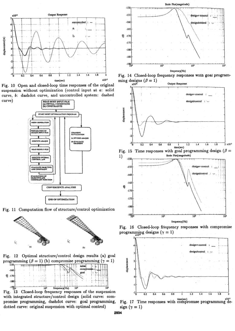
The computational flow of the optimization, along with the structural analysis and the optimal control, is illustrated in Fig. 11.
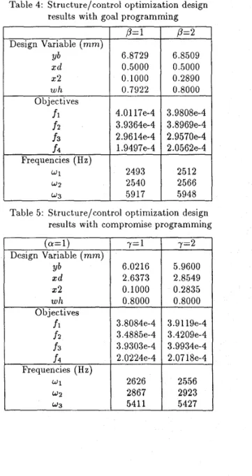
3.2. Optiiiiizatioii Results
For comparing with the results obtained in Part I, the same
weightings of the two multifunctional optimization techniques
are used. Both the indices
p
and y are chosen as 1 and 2for goal and compromise programmings, respectively. The optimization results are shown in Tables 4 and 5, and the optimal shapes in the finite element, mesh for the cases of
p
= 1 and y = 1 are illustrated in Fig. 12. We conclude in the following comments:(1) All the flap heights in the optimal design have a maxi-
mum allowable value 0.8mm, except for the case ,B = 1
of the goal programming to get a little smaller value
(CY=1) Design Variable (mm) Yb xd x2 w 11 Objectives
fl
f 2 f 3(2) As in Part I, the final results in raising natural fre- quencies are satisfactory. Without changing the original length, thickness and tip width of the suspension beam, the first and second natural frequencies are raised over 400 to 500 Hz, and the difference between the second and the third natural frequencies increases at least 500 Hz.
( 3 ) The final value of each objective function, as shown in Table 4 and 5, is larger than its minimum value and less than its maxirnum value. It is obvious that the nondom- inated solutions, or superior solutions, are not achieved, but a set of optimal solutions are obtained by making compromise between objective functions with each oth- er. y= 1 6.0216 2.6373 0.1000 0.8000 3.8084e-4 3.4885e-4 3.9303e-4
Table 4: Structure/control optimization design
f4 Frequencies (Hz) 2.0224e-4 2.0718e-4 w2 2540 2566 W 3
1
59171
5948 w 1 w2 w 3Table 5: Structure/control optimization design results with compromise programming
2626 2556 2867 2923 5411 5427 y=2 5.9600 2.8549 0.2835 0.8000 3.9 119e-4 3.4209e-4 3.9934e-4
4. Decision Making
In the above analyses, we have more than one alternative of optimal designs. The decision maker needs to select the I lost desirable alternative, and his rational choice requires &,erion by which he evaluates different alternatives and
place them in some form of ranking. Back to the original design objectives, the natural frequencies of the suspension assembly have to be raised so that it will not be excited easily by undesirable disturbances. A little different from Part I, we
investigate the closed-loop frequency responses of the optimal suspension shape with optimal controls. The single input point is selected at a , and the output is chosen at 0 where the slider head displacement is measured, as shown in Fig. 3. That way the symmetrical torsional modes are uncontrollable but observable. This will not cause system instability because that the torsional modes are seldom excited by out-of-plane disturbances that produce flying height fluctuations, and that those high-frequency torsional modes will decay fast due to the structural damping.
Figure 13 shows the closed-loop frequency responses of the suspension designed by goal programming
( p
= 1) and com- promise programming (y = I), respectively, compared to thefrequency response of the original suspension with an optimal control. It is interesting to find out that the low-frequency gain of the design with compromise programming is the small- est, while that with goal programming is the largest. This indicates that low-frequency disturbances may bring about less fluctuation of the slider head with the compromhse pro- gramming design than the other two designs. Moreover, the frequency response with the compromise programming design has more attenuation for higher frequencies, and a little larger bandwidth than that of goal programming design.
It is also necessary to convince people that the control yer- formance of the suspension assembly designed with integrat- ed structure/control optimization is superior to that without optimal control cost in the design as in Part I. Figure 14 is the frequency response of the suspension assembly with goal programming design. The solid curve (tlesign+control) rep- resents the case that the optimal control law is applied to the suspension designed with the objectives f i , f 2 and f3, while
the dashdot curve (design/control) describes the closed-loop system frequency response with integrated optimization of structure and control. Both frequency responses have almost the same peak value and bandwidth, that is, the mme fre- quency of input at which the output is attenuated to a factor
0.707 times the input. This is verified in Fig. 15 that both
time responses have a similar rise time. However, the inte- grated structure/control design gives much smaller resonant peak in frequency, that introduces more damping and leads to less settling time and less control effort in the regulatit,n con- trol. Similar results appears in the compromise programming design as shown in Figs. 16 and 17
5. Summary arid Conclusions
The integrated structure/control multiobjective optimization
nf the suspension assembly of hard disk drives has been p-
resented. In addition to the objective functions of nature frequencies as depicted in Part I, also incorporated in the op- timization is an optimal control performance index consisting of weighted system state regulation errors and control efforts. Two kinds of objectives have been achieved. First, the first and second natural frequencies are raised and the difference between the second and the third natural frequencies increas- es, that the suspension is not easily excited by undesirable dis- turbances. Second, as a vibration controller is implemented it is required that the vibration be suppressed in minimal time arid with least control effort. Both the goal programming and compromise programming techniques give feasible solutions, which would not be ideal, but the closest to the ideal ones in the sense that a best compromise is made among objectives. Furthermore, the final decision making requires more investi- gation on the closed-loop frequency and time responses. For the design of actively controlled structures, the control per- formances with the integrated structure/control optimization design are superior to those without the optimal control per- formance index in the design. The final solution may not be unique, but depends on additional engineering experience, manufacturing requirements, and so on.
Acknowledgment
This research was supported by National Science Council un- der Contmct No. NSC 82-0401-E-002-380.
References
Gilbert, M. G. and Schniiclt, D. I<., 1991, “Integrated Structure/Control Law Design by Multilevel Optimization,”
J. Guzdance, Vol. 14, No. 5 , pp. 1001-1006.
Livne, E., Schmit, L. A. and Friedmann, P. P., 1990, “To- wards Integrated Multidisciplinary Synthesis of Actively Con- trolled Fiber Composite Wings,” Vol. 27, No. 12, December, Rao, S. S., Venkayya, V. B. and Khot, N. S., 1988, “Game Theory Approach for the integrated Design of Structures and Controls,’’ AIAA Journal, Vol. 26, No. 4, pp. 463-469.
Tseng, C. H. and Lu, T. W . , 1994, “Multiobjective Opti-
mization in Mechanical and Structural Design,” t o appear in
Modelling and Scientific Computing.
pp. 979-992.
frequencj(Hz)
Fig. 9 Frequency responses of the original suspension with- out optimization (control input at a : solid curve, b: dashdot
curve, and uncontrolled system: dashed curve) 2833
-3 A - ; :
..;
I* 4 0 o i ot, o i 0.8i
i:z 114 1.6 1.81
W=) xi03Fig. 10 Open and closed-loop time responses of the original suspension without optimization (control input a t a : solid curve, b: dashdot curve, and uncontrolled system: dashed curve)
1
1
END OF OPI’IMIZATIONFig. 11 Computation flow of structure/control optimization
-165 - g -170- -175 - -180
-
-185-
I -1% 103 10‘ 10s *l=n9twFig. 14 Closed-loop frequency responses with goal program-
ming designs
( p
=
1) Output Respom X l O d design+control :-
L 5 e-
3
P .Y W time(sec)Fig. 15 Time responses with goal programming design
( p
=-155 - -160 - -165 - B -170 - -175 - -180
-
Bode Plot(magni1ude) -1& ’ ’ ‘ ’ ” ” ’ I 03 10‘ 1 0’ fre.quenC)(Hz)Fig. 16 Closed-loop frequency responses with compromise progra”&g designs (y = 1)
I design+contml ;
-
,desigdcontml :
-.-
Fig. 12 Optimal structure/control design results (a) goalprogramming
( p
= 1) (b) compromise programming (7=
1)5
0 0.2 0.4 0 6 0 8 1 1.2 1.4 1 6 1.8 2
Fig. 13 Closed-loop frequency responses of the suspension -2
with integrated structure/control design (solid curve: com-
promise programming, dashdot curve: goal programming, Fig. 17 Time responses with compromse programming de-
dotted curve: original suspension with optimal control) sign (y