Modified buffer layers for polymer photovoltaic devices
Chu-Jung Ko, Yi-Kai Lin, Fang-Chung Chen, and Chi-Wei Chu
Citation: Applied Physics Letters 90, 063509 (2007); doi: 10.1063/1.2437703 View online: http://dx.doi.org/10.1063/1.2437703
View Table of Contents: http://scitation.aip.org/content/aip/journal/apl/90/6?ver=pdfcov Published by the AIP Publishing
Articles you may be interested in
Plasmon enhancement of bulk heterojunction organic photovoltaic devices by electrode modification Appl. Phys. Lett. 93, 123302 (2008); 10.1063/1.2988190
Performance improvement of polymer solar cells by using a solution processible titanium chelate as cathode buffer layer
Appl. Phys. Lett. 91, 023509 (2007); 10.1063/1.2757125
Improving the stability of organic light-emitting devices by using a hole-injection-tunable-anode-buffer-layer J. Appl. Phys. 101, 054512 (2007); 10.1063/1.2472254
Enhanced thermal stability in organic light-emitting diodes through nanocomposite buffer layers at the anode/organic interface
J. Appl. Phys. 101, 033522 (2007); 10.1063/1.2434943
Investigation of electrostatic self-assembly as a means to fabricate and interfacially modify polymer-based photovoltaic devices
J. Appl. Phys. 94, 3253 (2003); 10.1063/1.1601315
This article is copyrighted as indicated in the article. Reuse of AIP content is subject to the terms at: http://scitation.aip.org/termsconditions. Downloaded to IP: 140.113.38.11 On: Thu, 01 May 2014 00:40:05
Modified buffer layers for polymer photovoltaic devices
Chu-Jung Ko
Department of Photonics, National Chiao Tung University, Hsinchu, Taiwan 300, Republic of China; Institute of Electro-optical Engineering, National Chiao Tung University, Hsinchu, Taiwan 300, Republic of China; and National Nano Device Laboratories, Hsinchu, Taiwan 300, Republic of China
Yi-Kai Lin and Fang-Chung Chena兲
Department of Photonics, National Chiao Tung University, Hsinchu, Taiwan 300, Republic of China and Display Institute, National Chiao Tung University, Hsinchu, Taiwan 300, Republic of China
Chi-Wei Chu
Research Center for Applied Sciences, Academia Sinica, Taipei, Taiwan 115, Republic of China
共Received 1 November 2006; accepted 3 January 2007; published online 7 February 2007兲 The influence of anode buffer layers on the performance of polymer photovoltaic devices based on blends of poly共3-hexylthiophene兲 and 关6,6兴-phenyl-C-61-buytyric acid methyl ester has been investigated. The buffer layers consist of poly共3,4-ethylenedioxythiophene兲:poly共styrenesulfonate兲 共PEDOT-PSS兲 doped with different concentrations of mannitol. Improved power conversion efficiency, up to 5.2%, has been observed by reducing the resistance of PEDOT:PSS after doping. One extrapolation method has been developed to exclude the resistance from the connection of the electrodes from the total device resistance. The results confirm that the device improvement is due to the reduction of series resistance of the PEDOT:PSS after the mannitol doping. © 2007 American
Institute of Physics. 关DOI:10.1063/1.2437703兴
Organic photovoltaic devices 共PVs兲 have attracted con-siderable attention due to their potential for flexible, light-weight, and low-cost applications of solar energy conversion.
Recently, the power conversion efficiency 共PCE兲 of
photo-voltaic cells around 5% has been realized.1,2 In addition, through the optimization of the donor/acceptor energy levels, the efficiency up to 10% is expected from recent simulation results.3 In practice, a high shunt 共parallel兲 resistance 共Rsh兲 and a low series resistance共Rs兲 are required simultaneously
for an ideal photovoltaic device.4,5 The Rsh usually reflects the degree of leakage current through the device, which re-lates to the overall quality of the films. Meanwhile, the Rsis
attributed to the Ohmic loss in the whole device, which in-cludes the resistance of the active layer, metal-organic con-tacts, the electrodes, and the parasitic probe resistance.5,6 Typically Rsdecreases with the thickness of the active layer
but increases when the operation temperature or the intensity of incident light becomes higher.7 Furthermore, it has been reported that the bulk resistance of the indium tin oxide 共ITO兲 of the devices with an area larger than 0.01 cm2 domi-nates the series resistance of organic PVs based on small molecules.6
To facilitate hole injection, higher work function materials are preferred as the anode of PVs. Thus, an extra interfacial layer, poly共3,4-ethylenedioxythiophene兲/ poly共styrenesulfonate兲 共PEDOT:PSS兲, which has higher work function 共5.2 eV兲,8 is usually applied to modify the surface of ITO共4.7 eV兲.9On the other hand, Aernouts et al. indicated that an improper PEDOT:PSS layer will reduce the short-circuit current 共Isc兲 and fill factor 共FF兲 owing to the increased series resistance.10 In addition, Zhang et al. re-ported that hole extraction from polymer PVs could be im-proved by doping polyalcohols into the PEDOT:PSS.11,12 Al-though it is well known that the conductivity of the doped
PEDOT:PSS increased over two orders of magnitude after doping with polyalcohols,12 only few attempts so far have been made to study the significance of the bulk resistance of PEDOT:PSS in polymer PVs.
In this work, mannitol 共Aldrich兲, a structure isomer of sorbitol, was doped into two kinds of PEDOT:PSS,
Baytron® P关PEDOT-PSS共P兲兴 and Baytron® PVP CH8000
关PEDOT-PSS共P兲兴, with different resistivities 共1 and 1 ⫻105⍀ cm兲, to evaluate the effect of the resistance of the doped PEDOT:PSS on the efficiency of the polymer PV. To fabricate the devices, PEDOT:PSS was firstly spin coated on the ultraviolet ozone treated ITO. After annealing the PEDOT:PSS film at 140 ° C for 1 h, the active layer poly 共3-hexylthiophene兲 P3HT 共Rieke Met. Inc.兲 and
关6,6兴-phenyl-C-61-buytyric acid methyl ester PCBM 共Nano-C兲 共1:1 in
weight ratio兲 were then spin coated from
1,2-dichlorobenzene to from a 205± 10 nm thin film. The pre-pared organic film was then treated following the so-called solvent annealing procedures as described in Ref.2. Finally, Ca and Al electrodes were deposited via thermal evaporation at the cathode. The active area of the device is 0.12 cm2. The resistivity of PEDOT:PSS was measured by four-point probe station 共Napson, RT-80兲. The current-density–voltage 共J-V兲 curves were measured by a Keithley 2400 source-measure unit. The photocurrent was obtained under illumination from a Thermal Oriel solar simulator共AM1.5G兲. The illumination intensity used was calibrated by a standard Si photodiode detector with KG-5 filter共Hamamatsu, Inc.兲. The calibration method based on IEC-69094-1 spectrum followed the proce-dures described in Ref.13.
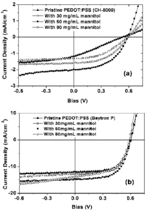
Figure1共a兲shows the J-V characteristics of the devices
under illumination 共100 mW/cm2兲, with different doping
concentrations of mannitol in the PEDOT-PSS共EL兲. The de-vice with pristine PEDOT:PSS共EL兲 shows poor performance with open-circuit voltage共Voc兲=0.53 V, short-circuit current density共Jsc兲=1.17 mA/cm2, and FF= 26.8%. The calculated a兲Electronic mail: [email protected]
APPLIED PHYSICS LETTERS 90, 063509共2007兲
0003-6951/2007/90共6兲/063509/3/$23.00 90, 063509-1 © 2007 American Institute of Physics This article is copyrighted as indicated in the article. Reuse of AIP content is subject to the terms at: http://scitation.aip.org/termsconditions. Downloaded to IP:
PCE is equal to 0.17%. On the other hand, after doping of
mannitol 共30 mg/ml兲, the Jsc and FF both increased and,
thus, the PCE also increased to 0.34%. After further increas-ing the dopincreas-ing concentration to 60 mg/ ml, the Jsc and FF
reached 1.33 mA/ cm2 and 42.8%, respectively. However,
the efficiencies slightly decreased after doping with 90 mg/ ml mannitol. It is worthy to note that the FF is rela-tively low, 26.8%, for the device with pristine PEDOT:PS-S共EL兲, implying a higher series resistance and a lower shunt resistance. After modification with mannitol, the FF was im-proved to nearly 50%,14 indicating that the series and/or the shunt resistance have been improved. The improvement of the device performance could be due to the reduction of the resistance of the PEDOT:PSS upon the doping of mannitol, leading to a decrease of the device Rs. In addition, it has also
been suggested that the increase of series resistance will re-duce the effective internal electric field in the active layer, which is essential for efficient charge collection to the elec-trodes from an organic photovoltaic model.15 Consequently, the device efficiency will be lower.15
Since the resistance of PEDOT:PSS has been proven to be one of the issues in polymer PVs, highly conducting PEDOT-PSS共P兲 doped with mannitol was used instead as the buffer layer for the PVs to further improve the performance
关Fig. 1共b兲兴. With 60 mg/ml of mannitol added, the device
exhibits pronounced improvement with Jsc= 14.7 mA/ cm2
and FF= 60.1%, while Vocremains nearly constant at 0.59 V. The corresponding PCE is 5.2%, which is among the highest values reported in organic solar cells. On the other hand, the efficiency decreased after doping with 90 mg/ ml mannitol due to a relative low FF. The lower FF may come from the
lower shunt resistance, which was induced by random leak-age current in higher conductivity PEDOT:PSS layer. The excess mannitol would cause serious phase separation and more defects in the PEDOT:PSS, inducing leakage through the device. A summary of the device performance using PEDOT-PSS共P兲 is shown in TableI. In the table, it is found that the higher concentration of polyalcohol presented, the lower the resistivities of PEDOT:PSS became. Meanwhile, the Rsis decreased as predicted. Accordingly, the resistivity
of PEDOT:PSS influences the entire device efficiency. Previously, different PEDOT:PSS have been used as the
buffer layers of the polymer PVs.12 The active layer was
polyfluorene copolymer blended with PCBM. In that cases, it was found that the short-circuit current increased with the high conductivity of the buffer layer, but the Vocand the FF decreased. On the other hand, in our cases, the decreases of
Vocand FF were not apparent owing to the sufficiently high shunt resistance, thus improving the PCE overall. It is prob-ably due to the fact that the concentration of the dopants is optimized, and the numbers of defects and leakage paths of
the semiconducting layer共P3HT:PCBM兲 are much lower.
To further investigate the effect of the doping on the Rs
and Rsh of the device, the J-V characteristics of these solar cells with different modified anodes were measured in the dark 共Fig. 2兲. As shown in Fig. 2共a兲, at reverse 共negative兲 bias and at the linear regime of forward bias, where the cur-rent is limited by Rshdue to the leakage current, the current gradually increased with the dopant concentration. The in-creasing current with doping concentration further supports that the excess mannitol causes the device leakage. On the
FIG. 1. Current/voltage characteristics of polymer PVs with different con-centration of mannitol-doped anodes: without doping共䉱兲; with 30 mg/ml doping共씲兲; with 60 mg/ml doping 共쎲兲; and with 90 mg/ml doping 共䊊兲 in 共a兲 low conductivity, 10−5S / cm, and共b兲 high conductivity, 1 S/cm,
PE-DOT: PSS. All device were measured under illumination of AM1.5 共100 mW/cm2兲.
TABLE I. Performance of ITO/ PEDOT: PSS共P兲/P3HT:PCBM/Ca/Al photovoltaic devices with different concentration of mannitol under illumi-nation of AM1.5共100 mW/cm2兲. Anode Voc 共V兲 Jsc 共mA/cm2兲 FF 共%兲 PCE 共%兲 Rsa 共⍀ cm2兲 Resistivityb 共⍀ cm兲 Pristine PEDOT/PSS 0.60 12.0 63.4 4.5 1.90 20.29 30 mg/ ml mannitol in PEDOT/PSS 0.59 13.1 63.2 4.9 1.42 3.72 60 mg/ ml mannitol in PEDOT/PSS 0.59 14.7 60.1 5.2 1.29 0.53 90 mg/ ml mannitol in PEDOT/PSS 0.59 13.8 55.2 4.5 1.01 0.16
aCalculated from the I-V curves in the dark. bMeasured from the four-point probe.
FIG. 2. Current/voltage characteristics with different concentrations of man-nitol. All devices were measured in the dark.
063509-2 Ko et al. Appl. Phys. Lett. 90, 063509共2007兲
This article is copyrighted as indicated in the article. Reuse of AIP content is subject to the terms at: http://scitation.aip.org/termsconditions. Downloaded to IP: 140.113.38.11 On: Thu, 01 May 2014 00:40:05
other hand, in the space charge limited current region 共⬎1 V兲, the current slightly increased because of the lower series resistance upon doping.16
Technically, major contributions to the Rs include the
bulk resistance共Rs,bulk兲 and the contact resistance 共Rs,contact兲.
The Rs,contactoriginates from the interface between the
elec-trodes and the active layer; the Rs,bulk comes from the bulk
resistance of organic layers 共P3HT:PCBM blends and
PE-DOT:PSS兲 and electrodes 共ITO and cathode metals兲. How-ever, it has been reported that the ITO resistance contributes to the Rs seriously in the device with the area larger than
0.01 cm2.6
Consequently, the resistance coming from the connection of the ITO anode should be considered as well for the large-area devices. In our cases, expect the P3HT:PCBM, the large area of ITO may also significantly contribute to the Rs,bulk. Furthermore, considering that the
modified PEDOT:PSS is highly conductive, it is interesting to see if the modified “anode structure,” consisting of both ITO and modified PEDOT:PSS, could reduce the overall de-vice resistance by reducing the surface resistance. To further understand how the doping of mannitol affects the resistance, the devices with different lateral distances between the an-odes and the cathan-odes have been fabricated, as shown in the inset of Fig.3. The lateral distance is defined as the separa-tion between the centers of the anode and the cathode. From the Fig.3, it can be see that the total series resistance of the whole devices increases with the increasing lateral distance, suggesting that the surface/sheet resistance of ITO electrodes indeed contributed seriously to the total device resistance. Furthermore, Fig.3 also reveals that the Rs decreased with
increasing concentration of mannitol. The extrapolations of the fitting curves while the lateral distance equals to zero gives the net resistance Rs,net, excluding the resistances of the
cathode and the anode in the lateral direction. Consequently,
Rs,net should be independent of the geometry design of the
device, since the resistance from the connections has been removed. The calculated Rs,net is 1.841⍀ cm2 for pristine PEDOT:PSS. In contrast, with the higher doping concentra-tion into PEDOT:PSS共P兲, Rs,net falls to 1.197, 1.024, and
0.873⍀ cm2 while doping 30, 60, and 90 mg/ ml mannitol,
respectively. On the other hand, the slopes in the four
differ-ent series of devices with differdiffer-ent mannitol concdiffer-entrations are almost identical, indicating the fact that the resistance in the lateral direction, which may be contributed from both ITO and PEDOT:PSS, is uniform. In other words, the value of lateral/sheet resistance only strongly depends on the ITO conducting area but depends weakly on the kinds of the PEDOT:PSS used, since the conductivity of ITO is much higher than that of PEDOT:PSS thin films. It suggests that the doping of PEDOT:PSS mainly affects significantly the series resistance only in the “vertical” direction共the inset of Fig.3兲.
The other possible reason for the enhanced efficiency comes from the increase of the device area. However, in our devices, the pattern of PEDOT:PSS is identical to that of ITO. Consequently, the effective area remains the same even after the conductivity enhancement of PEDOT:PSS. In addi-tion, the organic layers were further patterned by carefully scratching a trench between devices, which means that the surface conduction in this layer was no longer possible. However, similar device characteristics were still observed, indicating that the enhanced efficiency is not due to the in-crease of the area of the device.
In conclusion, the efficiency of polymer PVs has been improved by reducing the device series resistance by doping PEDOT:PSS with mannitol. From this study, it has been re-alized that the conductivity of PEDOT:PSS plays an impor-tant role in the polymer solar cells. Not only the bulk
resis-tance of the active film共P3HT:PCBM兲 should be concerned,
but the chosen of high-conducting PEDOT:PSS is also of importance to develop organic photovoltaic devices with high efficiency.
The authors would like to thank the financial support
from National Science Council, ROC
共NSC-95-2221E-009-305 and NSC-95-ET-7-009-001-ET兲 and MOE ATU
program.
1W. L. Ma, C. Y. Yang, X. Gong, K. Lee, and A. J. Heeger, Adv. Funct.
Mater. 15, 1617共2005兲.
2G. Li, V. Shrotriya, J. S. Huang, Y. Yao, T. Moriarty, K. Emery, and Y.
Yang, Nat. Mater. 4, 864共2005兲.
3M. C. Scharber, D. Wuhlbacher, M. Koppe, P. Denk, C. Waldauf, A. J.
Heeger, and C. L. Brabec, Adv. Mater.共Weinheim, Ger.兲 18, 789 共2006兲.
4A. Moliton and J. M. Nunzi, Polym. Int. 55, 583共2006兲. 5J. M. Nunzi, C. R. Phys. 3, 523共2002兲.
6J. G. Xue, S. Uchida, B. P. Rand, and S. R. Forrest, Appl. Phys. Lett. 84,
3013共2004兲.
7I. Riedel, J. Parisi, V. Dyakonov, L. Lutsen, D. Vanderzande, and J. C.
Hummelen, Adv. Funct. Mater. 14, 38共2004兲.
8T. M. Brown, J. S. Kim, R. H. Friend, F. Cacialli, R. Daik, and W. J. Feast,
Appl. Phys. Lett. 75, 1679共1999兲.
9G. Yu, C. Zhang, and A. J. Heeger, Appl. Phys. Lett. 64, 1540共1994兲. 10T. Aernouts, W. Geens, J. Poortmans, P. Heremans, S. Borghs, and R.
Mertens, Thin Solid Films 403, 297共2002兲.
11F. L. Zhang, M. Johansson, M. R. Andersson, J. C. Hummelen, and O.
Inganas, Adv. Mater.共Weinheim, Ger.兲 14, 662 共2002兲.
12F. L. Zhang, A. Gadisa, O. Inganas, M. Svensson, and M. R. Andersson,
Appl. Phys. Lett. 84, 3906共2004兲.
13V. Shrotriya, G. Li, Y. Yao, T. Moriarty, K. Emery, and Y. Yang, Adv.
Funct. Mater. 15, 2016共2006兲.
14G. Dennler, C. Lungenschmied, H. Neugebauer, N. S. Sariciftci, and A.
Labouret, J. Mater. Res. 20, 3224共2005兲.
15B. Mazhari, Sol. Energy Mater. Sol. Cells 90, 1021共2006兲.
16C. Waldauf, M. C. Scharber, P. Schilinsky, J. A. Hauch, and C. J. Brabec,
J. Appl. Phys. 99, 104503共2006兲. FIG. 3. Series resistance Rsas function of the lateral distance between the
anode and the cathode in different doping concentrations; without doping 共䉱兲, with 30 mg/ml doping 共씲兲, with 60 mg/ml doping 共쎲兲, and with 90 mg/ ml doping共䊊兲. Inset: the device structure and the definition of the lateral distance.
063509-3 Ko et al. Appl. Phys. Lett. 90, 063509共2007兲
This article is copyrighted as indicated in the article. Reuse of AIP content is subject to the terms at: http://scitation.aip.org/termsconditions. Downloaded to IP: 140.113.38.11 On: Thu, 01 May 2014 00:40:05