DESIGN OF FIR FILTERS AND ALLPASS PHASE EQUALIZERS WITH PRESCRIBED MAGNITUDE AND PHASE RESPONSES BY TWO REAL CHEBYSHEV APPROXIMATIONS
Soo-Chang Pei and Jong-Jy Shyu
Department of Electrical Engineering, National Taiwan University Taipei, Taiwan, Rep. o f China
ABSTRACT
Since the coefficients of a FIR filter with arbitrary complex-valued desired frequency responses are neither symmetric nor antisymmetric, the Remez exchange algorithm cannot be applied directly. The problem can be solved by dividing the original complex approximation into two real ones such that the Remez exchange algorithm can be applied by slightly modifying the Park- McClellan program. This method is much easier than the currently existing methods using linear programming and the performance is satisfied. More importantly, the magnitudes of the resultant complex errors are also equiripple as the direct complex Chebyshev approximation designs. Numeri- cal design examples including lowpass filter and sine-delay FIR allpass phase equalizers are given to show the effectiveness of this approach. I. INTRODUCTION
Conventionally, we often use the we1 1-known McClellan-Parks program [ I ] to design the 1 inear phase FIR digital filters. But these filters need large length and long time delay when designed with sharp cutoffs. Hermann and Schues- sler proposed the method for designing minimum phase FIR filters C21 which cause less delay but introduce delay distortion due to the delay is not a constant for all frequencies. In order to design filters which have less delay than linear phase filters and have approximately constant group delay in the filter passband, recently Chen and Parks have used a standard linear programming algorithm to solve this complex approximation problem [31, and then Preuss designed them by the complex Remez exchange algorithm C41, which has recently been improved by Schulist C51.
In this paper, we divide the complex Cheby- shev approximation problem into two real Cheby- shev approximations, and each of them can be solved by using Remez exchange algorithm. This method is fast and easy, also the powerful McClellan-Parks program cna be. applied after slight modification. The overall performance j s satisfied and the magnitude of the total complex error is also equiripple
in
the Chebyshev sense. Moreover, the method can also be applied to design all-pass phase equalizers.11. PROBLEM FORMULATION FOR FIR DIGITAL FILTER DESIGNS WITH CONSTANT GROUP DELAY IN PASSBAND
The frequency response of a FIR digital filters with real impulse response h(n), n=0,1,
...,
N-I is given byN-I -jnw n=O
H(w)= c h(n)e (1)
For simplicity, we consider only odd-length filter designs, let N=2Lt1 and
where he(n) and ho(n) are the even part and odd part of h(n) respectively and are given by
h(n)=he(n)+ho(n) n=O,I,.
..
,N-I (2)he(L-n)=he(L+n)=3Ch(L-n)th(Ltn)l,
n=0,1,2,.
.
.,L (3a)and
ho( L-n)=-ho( Ltn)=+[h( L-n)-h( Ltn)],
n=0,1,2,
...,
L (3b)Obviously he(L)=h( L) and h o ( L)=O; Thus 2L -jnw 2L -jnw n=O n=O H(w)= c he(n)e t c ho(n)e -jLw L ~ L * =e
C
c he(n)cosnwtj c ho(n)sinhwl (4) n=O n= 1 where and fi0(n)=2ho(L-n) n= 1,2,...,
L (5b) Then we use Eq.(4) to approximate the desired complex-valued frequency response D(w) given below jp(w) -jLw M(w)w =e IM(w)cos[LwtP(w)lt j M( w ) s in[Lw+P (w) 11 , D(w)= wvpassbands. ( 6 ) ( 0 , w P stopbands.where M(w) and P(w) are the amplitude response
and phase response of D(w) respectively. Then the design problem can be separated into two real approximated criteria, which are called by even and odd approximation respectively, i.e. even approximation: L , H (w)= c he(n)cosnwcxDe(w) e n=O M(w)cos[Lw+P(w)l, wppassband w v stopband for De(w)={
o,
(7b)and odd approximation: L A
Ho(w)= c ho(n)sin nw-Do(w) n= 1
M(w)sinCLwtP(w)l, w& passband wbstopband (7d) for DO(w)=
The overall filter impulse response h(?) can be obtained by combining the resultant he(n) and !o(n). Eq.(7a) and (7c) are formulated to find he(n) and fio(n) such that to minimize the maximum absolute weighted errors defined by
[=Maximum We(w) -IDe(w)-He(w)
1,
W Y passband/stopband (8a)
I
=Maximum Wo(w)I
Do (w)-Ho(w)I
,w
passband/stopband (8b) and odd approximation respectively, where We(w) and Wo(w) are the weighting functions.The main differences between this problem and the conventional filter approximation problem are in the desired responses for even and odd approximation, the original McClellan-Parks program can be easily modified to fit this problem. Also the weighted errors for two real approximations are each equiripple, if the weighting functions are chosen the same for both even and odd approximations (We(W)=Wo(W)=W(W)>O), then the magnitudes of the overall complex errors are also equiripple in the complex Cheby- shev sense. This separate appromixation approach has the simplicity advantages and easy implement- ation for practical applications.
Due to the degree of freedom for odd appro- ximation is one less than that for even approxi- mation, the peak error of the former is generally larger than that of the latter. Suppose the peak errors of even and odd approximation are
ae
and 60 respectively, i.e.EXAMPLE 1: Design of Low-pass Filters.
A 31 point lowpass filter with L=15, group delay r=12 CP(w)=-12wl, a passband [0,0.061 and a stopband C0.12,0.51 is considered in the design specifications. If the passband weighting is 1 and the stopband weighting is 10 for both even approximation and odd approximation, the frequency magnitude and group delay responses are shown in Fig.l(a) and (b) respectively. Fig.l(c) shows the magnitude of the overall complex error, in which the peak value is 0.04404 and 0.004401 in stopband.
111. DESIGN OF FIR ALLPASS PHASE EQUALIZERS
For a FIR allpass filter, in which its magnitude response is approximately unity with some prescribed phase characteristics, i.e.
-jLw j@(w) -jLw D(w)=e .e , O<W< n O<w< n (11) =e
I:
cos @(w
) t j s i n @(w
) 3 ,where @(w) is the phase response and a prescribed function o f w; The design problem is similar to that in Section 11, i.e. we wish to minimize the maximum absolute error (W(w)=l) defined as
L
n=O
1
IE,(W)I
)=maximurnJcosa(w)- c Fi,(n)cosnwl, 05wlnfor even approximation, and L n=O
I
IE~(w)I
I=maximumlsine(w)- c fiO(n)sinnwl, O<w<nfor odd approximation.
Due to the phase discontinuity at zero and folding frequencies, relaxation of the band edge specification for the odd approximation is permitted such that better result will beobtained, that is to say that, Eq.(l2b) can be reformulated as below to minimize
L n=O
1
I E ~ ( W )I
I=maximumlsin@(w)- c fiO(n)sinnwl, wo<w<n-wo and wO<<n (13) If the phase @(w) is symmetric or antisym- metric about w= n / 2 , the FIR allpass filter can be implemented with one-half the usual number of multiplications, in a manner analogous to the linear phase Case [SI. These results are sum- marized as below: (14) for @(w) even h(L-k)=-h(L-k), k odd h(L-k)=h(L+k), k even andh( L-k)=h( Ltk)=O, k odd, for about @(w) n/2 odd (15) The output coefficients of Eq.(15) are not
actually zero in practice, however they are generally very small, we simply set these coeffi- cients to zero for keeping the antisymmetry of the phase @(w).
EXAMPLE 2: Design of Sine-Delay Allpass Phase Equalizers
The desired frequency response is a unit amplitude and a sinusoidial phase characteristic
N- 1
Arg D(W)=-(~)W-BCOS w (16)
where @(W)=-fjCOS w is antisymmetric about w=n/2,
and the group delay is
(17) d N- 1
T (w) =-aArg D( w) =- - B s in w
2
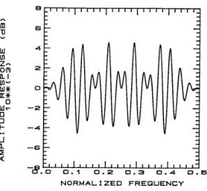
A 61 point Sine-delay allpass filter is designed with L=30, B=2n and w0=0.04, Fig.2(a) and (b) show the magnitude response (magnified version) and group delay response respectively, and the peak magnitude error is 0.0005249 which is much smaller than 0.000931 in [61.
IV. CONCLUSION
By separately approximating the real and imaginary parts of FIR filter complex-valued frequency response, McClellan-Parks program can be slightly modified to design the general FIR
filters and allpass phase equalizers very effec- tively. This approach is much easier than the current existing linear programming techniques, and the performance is satisfied, more important- ly the overall complex errors are also equiripple
in the complex Chebyshev sense. This approach has several practical advantages such as fast design time and easy implementation with compara- ble accuracy. REFERENCES
Cl1
C21 C31 C41 E51 [61J.H. McClellan, T.W. Parks and L.R. Rabiner, "A Computer program for designing optimum FIR linear phase digital filters", IEEE Trans. Audio Electroacoust. vol.AU-21, pp.506-526, Dec. 1973.
0. Herrmann and H.W. Schuessler, "Design of nonrecursive digital filters with minimum phase", Electron. Lett., vol. 6 , no. 1 1 , pp.329-330, May 1970.
X. Chen and T.W. Parks, "Design o f FIR filters in the complex domain," IEEE Trans. Acoust., Speech, Signal Processing, vol.ASSP- 35, pp.144-153, Feb. 1987.
K. Preuss, "On the design of FIR filters by complex Chebyshev approximation," IEEE Trans. Acoust., Speech, Signal Processing, vol.ASSP-37, pp.702-712, May 1989.
M. Schulist, "Improvements of a complex FIR filter design algorithm," Signal Processing, vol. 20, pp.81-90, May 1990.
K. Steiglitz, "Design of FIR digital phase networks," IEEE Trans. Acoust., Speech, Signal Processing, vol.ASSP-29, pp. 171-176,
A m
!
W cn z 0 m W U W 0 3 I- -I Q I: 4 a-
Fig.1 Apr. 1981. - 4 0 -50 -60 -704
-=8.0
0.1 0.2 0.3 0 . 4 0 . 5 N O R M A L I Z E D F R E Q U E N C Y ( a )Example 1 : A 31 point lowpass filter with f =0.06, f,=0.12 and r.12. (a) magnitude response, ( b ) group delay response.
( c ) equlripple magnitude response o f complex error. (d) equiripple error f o r even approximation. (e) equiripple error f o r odd approximation. (f) trace o f complex error in t h e passband C-0.06,0.061 (dotted line: error radius o f
C51). (9) trace o f complex error in t h e stopband C0.12.0.881 (dotted line: error radius o f [SI).
P
>. J W O a 3 0 U U a Fig.1 n LLm W * Low 20 O F a ulu WO
uu
U w w 3 X I-W -J Ja 0.2 I O <U O!. a Fig.1 6 cI m U 6 cI m U " 4 W Lo Z - om 2 L l Lo" w* 0 U* 0 w r - 2 0 3 I- - 4 . - 1 0 5 I8.0
0 . 1 0 . 2 0.3 0 . 4 0.5 N O R M A L I Z E D F R E Q U E N C Y (b)Example 1: A 31 point lowpass filter with f =0.06, fs=0.12 and 7.12. (a) magnitude response, (b) group delay response. (c) equiripple magnitude response of ccmplex error. (d) equiripple error for even approximation. ( e ) equiripple error for odd approximation. (f) trace o f complex error in the passband [-0.06,0.06] (dotted line: error radius of C.51). (9) trace of complex error in the stopband [0.12,0.881 (dotted line: error radius of [SI).
P 50
>
4 0 30 20 1 08.0
0 . 1 0.2 0.3 0 . 4 0.5 N O R M A L I Z E D F R E Q U E N C Y (C)Example 1: A 31 point lowpass filter with f =0.06, fs=0.12 and 7112.
(c) equiripple magnitude response of complex error. (d) equiripple error for even approximation. ( e ) equiripple error for odd approximation. (f) trace of complex error in the passband [-0.06.0.061 (dotted line: error radius of [5]). (9) trace of complex error in the stopband C0.12.0.881 (dotted line: error radius of C.51).
P
(a) magnitude response, (b) group delay response. -I a I: a
-8.0
0 . 1 0.2 0.3 0 . 4 0.5 N O R M A L I Z E D F R E Q U E N C Y (a)Fig. 2 Example 5 : A 61 point Sine-delay allpass phase equalizer for 0.025f50.48. (a) magnified magnitude response, (b) group delay response. >.
<
J W 0 a 3 0 01 LI 3 1 30 2s 2 8 27 26 25 2 4:
9 . 0 0 . 1 0 . 2 0.3 0 . 4 0.5 N O R M A L I Z E D F R E Q U E N C Y (b)Fig. 2 Example 5 : A 61 point Sine-delay allpass phase equalizer for 0.02<f<0.48. (a) magnified magnitude response, (b) group delay response.