Indoor Security Patrolling with Intruding Person Detection and
Following Capabilities by Vision-Based Autonomous Vehicle
Navigation
Student: Yu-Tzu Wang Advisor: Dr. Wen-Hsiang Tsai
Institute of Computer Science and Engineering National Chiao Tung University
ABSTRACT
A vision-based vehicle system for security patrolling by human detection and tracking in indoor environments is proposed. A vehicle with wireless control and a web camera is used as a test bed. A robot arm is equipped on the vehicle to hold the camera at a higher position and is used to change the orientation of the camera. First, a camera calibration method is proposed by use of a technique of angular mapping, which is based on the concept of spherical coordinate system. Next, a human detection module and a human tracking module are proposed, which use a color feature of the face and that of the rough shape of the human body to recognize human beings. To track a target person, a cloth region intersection method is proposed to predict the motion of the person. In addition, a vehicle escape function is proposed, which is designed for the vehicle to move away from offensive strangers by a technique of safe-distance keeping. Good experimental results show the flexibility and feasibility of the proposed methods for the application of indoor security patrolling.
ACKNOWLEDGEMENTS
The author is in hearty appreciation of the continuous guidance, discussions, support, and encouragement received from his advisor, Dr. Wen-Hsiang Tsai, not only in the development of this thesis, but also in every aspect of her personal growth.
Thanks are due to Mr. Tsung-Yuan Liu, Mr. Chih-Jen Wu, Mr. Kuo-Feng Chien, Mr. Yen-Long Chen, Mr. Kai-Li Chiang, Miss Pei-Pei Chen, Miss Chia-Yu Hsu, and Miss Yi-Lin Wang for their valuable discussions, suggestions, and encouragement. Appreciation is also given to the colleagues of the Computer Vision Laboratory in the Institute of Computer Science and Engineering at National Chiao Tung University for their suggestions and help during her thesis study.
Finally, the author also extends her profound thanks to her family for their lasting love, care, and encouragement. She dedicates this dissertation to her parents.
CONTENTS
ABSTRACT...i ACKNOWLEDGEMENTS...ii CONTENTS... iii LIST OF FIGURES ...v Chapter 1...1 1.1 Motivation...11.2 Survey of Relative Studies...2
1.3 Overview of Proposed Approach...3
1.4 Contributions...5 1.5 Thesis Organization ...6 Chapter 2...7 2.1 Introduction...7 2.2 System Configuration ...8 2.2.1 Hardware Configuration ...8 2.2.2 Software Configuration...11
2.3 Human Detection Principle and Major Steps in Proposed Process ...11
2.4 Human Tracking Principle and Major Steps in Proposed Process...13
Chapter 3...15
3.1 Introduction...15
3.1.1 Coordinate Systems ...16
3.1.2 Viewing Angles of Camera ...18
3.1.3 Directional Angles of Camera...20
3.2 Review of Perspective Projection ...21
3.3 Calibration of Camera by Angular Mapping ...24
3.3.1 Linear Angular Transformation...24
3.3.2 Nonlinear Angular Mapping ...26
3.4 Vehicle Location Techniques Using Angular Mapping ...31
3.4.1 2D to 3D Distance Transformation ...32
3.4.2 Angle Transformation between Coordinate Systems...33
Chapter 4...35
4.1 Overview of Human Detection ...35
4.2 Proposed Process of Human Detection...36
4.3.1 Skin Region Segmentation Using Color Classification...38
4.3.1.1 YCbCr Color Space ...38
4.3.1.2 Adopted Skin Color Model...41
4.3.2 Detection of Human Face by Ellipse Shape Fitting...42
4.4 Human Body Detection by Motion Analysis...45
4.4.1 Motion Detection by Shift Tolerance Blockwise Frame Differencing ...45
4.4.2 Human Body Detection...49
4.4.3 Some Experimental Results ...51
Chapter 5...53
5.1 Basic Idea of Human Tracking ...53
5.2 Proposed Process of Human Tracking ...54
5.3 Extraction of Colors of Human Clothes...56
5.4 Human Tracking by Motion Analysis of Human Clothes...59
5.4.1 Recording of Human Motion...60
5.4.2 Motion Detection by Cloth Region Intersection...60
5.5 Applications to Stranger Tracking and Person Following ...61
5.5.1 Stranger Tracking...61 5.5.2 Person Following ...61 5.5.3 Experimental Results ...62 Chapter 6...65 6.1 Overview...65 6.2 Principle of Escape ...66
6.3 Distance Computation from The Vehicle to A Stranger...68
6.4 Method for Adjustment of Camera Orientation for Human Monitoring .71 Chapter 7...73
7.1 Experimental Results ...73
7.2 Discussions ...77
Chapter 8...78
8.1 Conclusions...78
8.2 Suggestions for Future Works...79
LIST OF FIGURES
Figure 1.1 A flowchart of proposed system ...5
Figure 2.1 The vehicle Pioneer3 used in this study. (a) The front of the vehicle. (b) The flank of the vehicle...9
Figure 2.2 The structure of proposed system...10
Figure 2.3 An illustration of Human Detection Process ...12
Figure 2.4 An illustration of the human tracking process...14
Figure 3.1 The coordinate systems used in this study. (a) The image coordinate system. (b) The vehicle coordinate system. (c) The spherical coordinate system. (d) The polar coordinate system. ...17
Figure 3.2 The viewing angles of the camera. (a) The horizontal viewing angle α. (b) The vertical viewing angle β...19
Figure 3.3 An illustration of the image coordinate system confined by the ranges of the longitude and the latitude values...20
Figure 3.4 The pan angle of the camera. (a) 0≤θc≤ (b) 0π ≥θc ≥ − ...21 π Figure 3.5 The tilt angle of the camera. (a) 0 2 c π ϕ ≤ ≤ (b) 0 2 c π ϕ ≥ ≥ − ...21
Figure 3.6 Concept of perspective projection. ...23
Figure 3.7 Image coordinate system mapping into real world...23
Figure 3.8 The relationship of image resolution and the viewing angles. (a) The horizontal direction. (b) The vertical direction. ...25
Figure 3.9 An illustration of the image coordinate system confined by the ranges of image resolution...26
Figure 3.10 An illustrate of Attaching the lines on the wall. ...29
Figure 3.11 A method of finding image coordinates of tessellated points in the grabbed image. (a) A grabbed image with tessellated points. (b) The tessellated points marked by yellow points...30
Figure 3.12 The points on the wall corresponding to of yellow points in Figure 3.11(b). ...30
Figure 3.13 An illustrate of the interpolation method that a region contains the point I in the ICS. ...31
Figure 3.14 The distance between the object and the vehicle. (a) The camera has no tilting, i.e. φc = 0. (b) The camera has a tilt angle of φc. ...33
Figure 4.1 The proposed process of human detection. ...37
Figure 4.2 YCbCr color model with Y = 126...40
Figure 4.3 YCbCr color models with different Y values. ...40
Figure 4.4 3D YCbCr color model in [23][24]. ...41
Figure 4.5 Distribution of conditional probability density function of skin color in Cb-Cr plane [20]. ...42
Figure 4.6 The elliptic skin model used in this study...42
Figure 4.7 The detection of human face by ellipse shape fitting. (a) Input image. (b) Skin Segmentation. (c) Rectangular and elliptic mask. (d) Detected face region. ...44
Figure 4.8 The image is segmented into blocks...47
Figure 4.9 The searching window. ...48
Figure 4.10 The blocks within in the searching window in Ir...48
Figure 4.11 An example of blockwise frame difference images...49
Figure 4.12 The order of the images: the current image, the reference image and the difference image using the proposed blockwise frame difference. (a) The person regions are close. (b) The person regions are far. (c) The person only exists in one of the images (d) No person exists in both images. ...52
Figure 5.1 A cycle of the human tracking process. ...54
Figure 5.2 The drawing of Vitruvian Man by Leonardo da Vinci. ...58
Figure 5.3 The body proportion according to Vitruvius. ...59
Figure 5.4 The application for stranger tracking. ...62
Figure 5.5 The application for person following. ...62
Figure 5.6 The consecutive images which were taken by the camera equipped on the vehicle when the vehicle tracked the target person. The order of the images is (a) through (j). ...63
Figure 6.1 The process of escape for the vehicle...67
Figure 6.2 The safe-distance for the vehicle. The vehicle is in an unsafe state when a person detected within the green circle. Else if the person is in the yellow area, the vehicle is in a buffer state. Else, it is in a safe state...68
Figure 6.3 The illustration of the distance between the person and the vehicle. (a) Distance computing using length of the face. (b) Distance computing using length of the clothes...69
Figure 6.4 The experimental result that the vehicle moves backward to the last position when the vehicle detected the fact that the person is too close. (a) The images grabbed by the camera equipped on the vehicle. (b) The images captured from a third person’s viewpoint...72 Figure 7.1 An interface of the experiment. The green box shows the image stream and
the blue box shows the input image at this moment. The yellow box shows the difference image and the red box shows the output image. ...74 Figure 7.2 An experimental result of human body detection in the proposed system.(a) The input image. (b) The difference image. (c) The output image. ...75 Figure 7.3 An experimental result of face detection and the extraction of the cloth. (a)
The output image with a detected face region and the extracted cloth region by region growing. (b) The image of the extracted cloth. ...75 Figure 7.4 An experimental result of human tracking using the intersection of the cloth images. (a) The input image. (b) The output image...76
Chapter 1
Introduction
1.1 Motivation
In recent years, autonomous vehicle guidance by computer vision techniques in both indoor and outdoor environments has been widely and intensively studied. The vision-based autonomous vehicle has been used in numerous applications, including security patrolling. For the application of security patrolling, not only vehicle learning and navigation but also stranger intrusion detection and tracking are important research topics. Use of an autonomous vehicle equipped with a video camera is more “active” to accomplish the task of human tracking than use of traditional stationary cameras. The activeness nature comes from the dynamic movement capability of the vehicle, which makes monitoring of any corner in an environment possible.
Vision-based object detection and tracking is one of the most challenging issues in computer vision. Compared to other sensing devices, visual sensors like video cameras provide more information and higher-level intelligence to make logical decisions for vehicle control. However, along with the advantages of the vision-based system come additional difficulties. One of the difficulties is detection of moving objects in changing backgrounds. Detection and tracking of irregular-shaped targets, especially human beings, demands complicated solutions by pattern recognition and motion detection techniques.
Stationary cameras, usually fixed in houses or open-space environments, can only record scenes into videos passively, and abnormal situations in videos are usually
observed by humans. Instead of inspecting videos by manpower, some existing researches of indoor security monitoring with stationary cameras focus on automatic detection of intruding humans in images or videos. It takes a lot of cameras to monitor every corner in a house. Hence, it is a good choice to use a vision-based autonomous vehicle, which has mobile ability, to reducethe use of cameras. Moreover, the vehicle can repeat identical steps, patrols all day, and needs only electric power.
Besides security patrolling, it is desired to design a navigation method by which a person can lead the vehicle to any desired place. Such a method creates more applications for the vehicle. The system can be used as an autonomous handcart or a shopping car to help humans carrying heavy stuff. Many systems of person following use a special mark for detecting the person’s location, which puts more restrictions on person identification.
In this study, it is desired to develop a vision-based vehicle system for indoor security patrolling. We propose a system to be capable of security monitoring, including detection and tracking of intruding persons. Moreover, the system also provides a function for person following without the need of special marks.
1.2 Survey of Relative Studies
In ordinary video surveillances, human detection is performed by the use of fixed cameras with stationary backgrounds, which focuses on analysis of moving objects by frame differences and background establishment [1][2]. However, it is easier to detect moving objects in image sequences with stationary backgrounds. When moving cameras are used, these conventional frame difference-based techniques cannot be applied to detect moving objects since the scenes taken by the camera are unstable.
In the case of human detection by mobile cameras, many approaches have been proposed using various sensors and many kinds of features. To detect humans with non-stationary background, existing methods employ optical flow [3][4], direct camera motion parameter estimation [5], geometric transformation [6][7], dense stereo and motion measurements [8][9], or thermal infrared sensors for detection [10]. Unfortunately, the equipments of dense stereo and thermal infrared sensors are expensive. In some applications, direct camera motion parameters cannot be estimated. And geometric transformation is applied to detect motions under the assumption of uniform background.
Furthermore, many features have been used to recognize human beings, such as skin color [11], motion [12], depth [13], contour, and texture [14], etc. Since it is difficult to recognize humans in images using only a single feature, many systems use multiple features to distinguish human beings from other objects. Some systems extract skin color to detect human body parts, and track each part by motions [15][16]. Some systems detect moving parts first and analyze the shapes of the moving parts to detect human beings [17]. Heisele & Wohier proposed a system for detecting and tracking pedestrians by clustering of color image segmentation results [18]. By analyzing the cluster shape, they can find the regions of human legs. The system proposed by Papageorgiou extracts a set of wavelet features and applies a support vector machine (SVM) classifier [19].
1.3 Overview of Proposed Approach
In this study, we want to design a vision-based vehicle system for security patrolling by human detection and tracking in indoor environments. To achieve the goal, to recognize human beings and know their locations are necessary. The chief tools are the
proposed system is illustrated in Figure 1.1.
The proposed approach of the vision-based vehicle system for security patrolling includes four major parts. The first part is camera calibration. In this study, we calibrate the camera by a technique of angular mapping, which uses the concept of spherical coordinate system. After fixing a camera on the vehicle, the angular mapping calibration technique using image analysis is used to compute the direction between the vehicle and a target used for calibration. Since each point in the image represents a unique light ray from the viewpoint into the camera, the proposed calibration method is to define the view angle of each point. According to these angles and the height of the camera, we can know the relative locations of targets in images.
The second and the third parts are a human detection module and a human tracking module. Before the vehicle tracks a target person, how to detect human beings from the image is essential. Identifying human beings in images a conventional but sophisticated topic. We use a color feature of the face and that of rough shape of human body to recognize human beings. To recognize faces in images, the color and the shape of a pattern are the main features to make decision. In addition, if a human body shape is found in motion detection, the system will pay attention to the humanlike object to verify it.
After an intruding person is detected, the system will remember his/her clothing and track him/her. To track the target person, we propose a cloth region intersection method to predict the motion of the person. Also, we record all the motions of the target person, and compute accordingly a parameter for the motion prediction of the target person. Unless the face of the target person is captured by the camera clearly, the system will come back to the detection mode again and again.
The last part is a vehicle escape function. Sometimes, the intruding strangers might try to attack the vehicle. We designed a function for the vehicle to escape from offensive
strangers by a technique of safe-distance keeping. From the coordinates of the detected human face in the image, we can calculate the distance of a stranger. If the distance is shorter than the safe-distance we define in advance, the vehicle will be commanded to go to the last position in its path for escape.
Camera calibration Human detection Human tracking Vehicle escape function Target human clothing extraction Target human motion recording
Figure 1.1 A flowchart of proposed system
1.4 Contributions
The major contributions of this study are summarized as follows. (1) An angular mapping method for camera calibration is designed.
(2) A method of angular transformation from images to real world coordinates is proposed.
differencing is proposed.
(4) A method of face detection by image analysis is proposed.
(5) A technique for prediction of target object movement is proposed. (6) A technique for real-time human tracking is proposed.
(7) A method for escaping from a human being during vehicle navigation is proposed.
1.5 Thesis Organization
The remainder of this thesis is organized as follows. The system configuration of the vehicle and the principles of human detection and tracking are described in Chapter 2. In Chapter 3, the proposed method of angular mapping calibration and the technique for vehicle location are described. In Chapter 4, the proposed methods for human detection by image analysis are described. The proposed techniques for human tracking will be described in Chapter 5. The function for escape from humans by safe-distance keeping is described in Chapter 6. Some satisfactory experiments results are shown in Chapter 7. Finally, some conclusions and suggestions for future works are given in Chapter 8.
Chapter 2
System Configuration and
Navigation Principles
2.1 Introduction
A security patrolling system in an indoor environment is always required to be aware of stranger intrusion. Rather than waiting an intruding person to pass through the field of view of a monitoring system passively, tracking the intruding person actively by the use of an autonomous vehicle is more helpful.
To achieve this goal, a vehicle with wireless control and a web camera is used as a test bed for our research in this study. Because the target of detection is the human being, the camera must be fixed at a sufficient height from the ground. If the camera is located at a low position, it is difficult to observe the whole human body by the grabbed image. Hence, a robot arm is equipped on the vehicle to hold the camera at a higher position in this study. The arm is also used to change the orientation of the camera. The entire hardware equipment and software used in this study are introduced in Section 2.2.
To conduct human detection in an unknown indoor environment, we have to define some features for human detection. Based on the features, we can analyze the grabbed images to detect whether a person is in the image. In Section 2.3, we will describe the human detection principle and process proposed in this study. After a person is detected using the information of his/her clothes and location, the system
will enter the tracking mode. It will then compute the location and record the motion, of the target person, and moves the vehicle closer to the target person. The proposed principle and process will be introduced in Section 2.4.
2.2 System Configuration
In this study, we use the Pioneer 3, a rugged vehicle made by ActiveMedia Robotics Technologies Inc., as a test bed, on which an optional robotic arm is equipped, as shown in Figure 2.1. The arm can reach up to 50 cm (measured from the center of its base to the tip of its closed fingers). The tip of the arm is enabled to hold a digital web camera, AXIS210. The camera is IP-based with a build-in web server. We get the image captured and control the vehicle via wireless communication through computer networks.
2.2.1 Hardware Configuration
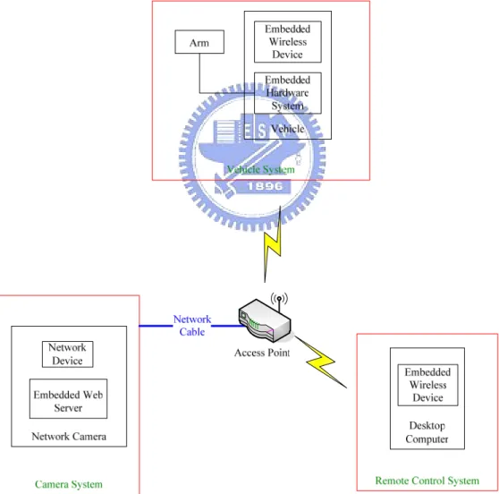
The entire navigation system is composed of three parts, as shown in Figure 2.2. The first part is a vehicle with a build-in wireless device and an embedded control system. The vehicle has an aluminum body of the size of 44cm×38cm×22cm with three wheels of the same diameter of 16.5cm. The vehicle can reach a forward speed of 160cm per second and a rotation speed of 300 degrees per second. There are three 12V batteries in the vehicle which supply the power. The vehicle can run 18-24 hours with the three fully charged batteries. By a user’s command, the embedded control system can control the vehicle to move forward or backward or to turn around. The system is also able to return some status parameters of the vehicle to the user. The robot arm has five degrees-of-freedom, residing on the top platform of the vehicle.
(a) (b)
Figure 2.1 The vehicle Pioneer3 used in this study. (a) The front of the vehicle. (b) The flank of the vehicle.
The second part is a digital web camera. To increase the height of the viewpoint, the camera is held by the robot arm. Since the arm has a carry weight limit, we have to choose a camera which meets to the limit. However, the lighter the camera is, the less the capability of the camera is. The camera we adopt has no panning, tilting, and zooming functions. Still we can change the direction of the camera by controlling the robot arm. Because the signal issued by the camera is digital, the grabbed image has no noise. Moreover, the camera is directly connected to an access point by a network cable for transmission of the captured image. The resolution of the image grabbed in our experiment is 320 240× pixels for the reason of raising image processing efficiency.
and get the status information from the vehicle and the robot arm. All commands transmitted to the vehicle or to the camera are through the wireless network. There is an access point in our test environment which meets the IEEE 208.11b standard to offer a bandwidth for the remote control system to communicate with the vehicle and the camera. Both the vehicle and the remote control system own wireless devices to connect to the access point, and the camera connects to the access point via a network cable. In other words, we use the access point as a medium to connect the three parts of the proposed navigation system.
2.2.2 Software Configuration
The ActiveMedia Robotics provides an application interface ARIA to control the mobile robot. ARIA is an objected oriented interface which is useable under Linux or Win32 in C++ language. We use the ARIA to communicate with the embedded system of the vehicle. And we use the Borland C++ Builder as a development tool in our experiments.
2.3 Human Detection Principle and
Major Steps in Proposed Process
To conduct human tracking, we have to detect the existence of a person first. After a person is detected, the vehicle is moved to get close to the target. Since the web camera is the only sensor of the proposed system, we have to recognize human beings by image analysis.
In this study, we detect a person by face identification. There are three features, color, shape and motion, which we use for this purpose. When we get an image with the camera, we have to conduct two kinds of detections first at the same time. One is detection of skin-colored ellipses and the other is motion detection. Combining the results of these two kinds of detections, we define a moving skin color ellipse as a face of a person. Sometimes, the distance from the vehicle to the person is far, and the face cannot be detected in the grabbed image. Then we apply a human body detection process to the moving part to confirm if a person exists in the image or not. When an object similar to a human body is detected, the vehicle would be ordered to get closer to the object to take a clearer image of it.
If a face is detected by the system, the system will extract the information of the clothing and the system mode will be changed to the tracking mode and the vehicle would be commanded to do the tracking process. Otherwise, the system will stay in the detection mode. An illustration of the human detection process is shown in Figure 2.3.
2.4 Human Tracking Principle and
Major Steps in Proposed Process
While the system is in the tracking mode, it means that we have the information about the person’s clothing and the location of the person. We can search the new location of the person by the information of his clothing using of a prediction window.
Sometimes, a stranger might try to get close to the vehicle and attack it. For the reasons, we conduct face detection first to inference that the person faces the vehicle or turns his/her back to the vehicle. When a person faces the vehicle, a face will be detected, and we will compute the distance from the person to the vehicle. If the distance is shorter than a safe distance we define in advance, we order the vehicle to move backward to avoid possible attacks from the intruding person. Otherwise, we compute the moving direction of the person by information of the clothing and record the motion. Moreover, we propose a method of image intersection to predict the motion of the person. Combining the prediction and the record of the last motion of the person, we compute the possible movement of the person and command the vehicle to move to the person. The vehicle will then turn its head to aim at the person’s face and go forward for a distance. When the system loses the cloth region for region intersection or when the person disappears in the grabbed image, the system will finish the tracking process of the person and enter the detection mode to continue security patrolling. An illustration of the human tracking process is shown in Figure 2.4.
Chapter 3
Camera Calibration by Viewing
Angles
3.1 Introduction
While a vehicle is tracking a person, the relative position and distance of the target person are important information for the tracking process. Since the camera is the only sensor of the proposed system and the techniques of human detection and tracking are based on visual perception, camera calibration and image analysis techniques for 2D images are indispensable in this study. Through imaging with the camera, 3D world coordinate systems are mapped into 2D image coordinate systems. However, there is ambiguity in the inverse mapping from 2D image coordinates to the 3D world coordinates. Each point in the image is the projection result of a light ray onto the image sensor. The light ray can be described by a longitude angle and a latitude angle of the ray in the 3D world space. To define the corresponding longitude and latitude angles (or simply called longitude and latitude in the sequel) of each point in images, we propose a method of angular-mapping camera calibration. Unfortunately, we cannot define the longitude and the latitude independently because of the existence of nonlinear camera distortion. In this study, we propose to use a 2D mapping method to achieve the goal of angular-mapping camera calibration.
We will review the principle of perspective projection which is involved in the basic idea of the proposed calibration method in Section 3.2. And we will discuss the
detail of the proposed angular-mapping calibration method in Section 3.3. However, the position of the target object in the real world is what we are concerned with. We will propose a method to compute the location of the vehicle using angular mapping in Section 3.4.
Before describing the above-mentioned method, we first introduce the definitions of coordinate systems, and the viewing angles and directional angle of the camera for use in the study. We introduce the coordinate systems in Section 3.1.2 and the viewing angles of the camera in Section 3.1.1. Then, the directional angle of the camera will be introduced in Section 3.1.3.
3.1.1 Coordinate Systems
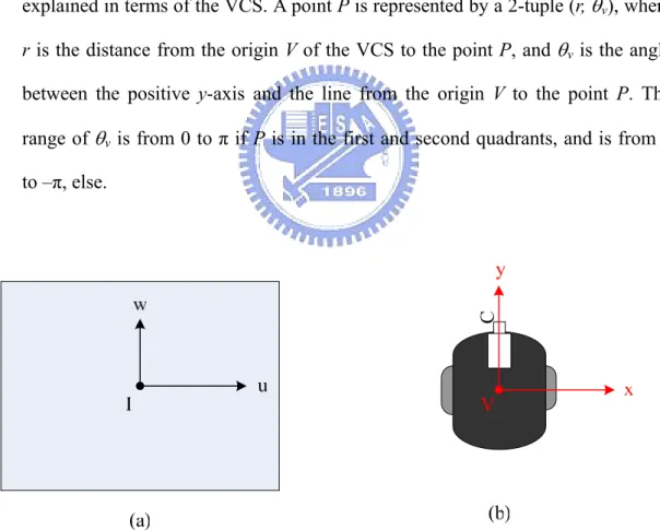
A few coordinate systems are used in this study, which describe the relative locations between the vehicle and objects. The coordinate systems are shown in Figure 3.1. The definitions of all the coordinate systems are stated in the following. (1) Image coordinate system (ICS): denoted as (u, v). The uv-plane of the system is
coincident with the image plane, and the image center, assumed to be the origin I of the ICS, will be described in detail in Section 3.2.
(2) Vehicle coordinate system (VCS): denoted as (x, y). The xy-plane is coincident with the ground, and the center of the VCS, the origin V, is taken to be the rotation center of the vehicle, which is the middle of the line segment connecting the two driving wheels. The x-axis of the system is parallel to the line segment of the two driving wheels and through the origin V. The y-axis is perpendicular to the x-axis and through V.
(3) Spherical coordinate system (SCS): denoted as (ρ, θ, φ). It is a 3D polar coordinate system. For convenience, we explain this system in terms of the 3D Cartesian coordinate system with coordinates (i, j, k). The ij-plane of the Cartesian
system is parallel to the uv-plane in the ICS. The origin S of the spherical system, which is also the origin of the Cartesian system, is the optical center of the camera. A point P at coordinates (i, j, k) in the Cartesian space is represented by a 3-tuple (ρ, θ, φ) in the spherical space. The value ρ with ρ≥ is the distance between 0 the point P and the origin S. The longitude θ is the angle between the positive
k-axis and the line from the origin S to the point P projected onto the ik-plane. The latitude φ is the angle between the ik-plane and the line from the origin S to the point P. The range of θ is from –π/2 to π/2 and the range of φ is the same.
(4) Polar coordinate system (PCS): denoted as (r, θv). It is a 2D system which may be
explained in terms of the VCS. A point P is represented by a 2-tuple (r, θv), where
r is the distance from the origin V of the VCS to the point P, and θv is the angle
between the positive y-axis and the line from the origin V to the point P. The range of θv is from 0 to π if P is in the first and second quadrants, and is from 0
to –π, else.
C
Figure 3.1 The coordinate systems used in this study. (a) The image coordinate system. (b) The vehicle coordinate system. (c) The spherical coordinate system. (d) The polar coordinate system.
j i k P(ρ,θ,φ) θ j k i ρ (c) S φ u w I v (r, v) x y P (d) r V
Figure 3.1 The coordinate systems used in this study. (a) The image coordinate system. (b) The vehicle coordinate system. (c) The spherical coordinate system. (d) The polar coordinate system. (continued)
3.1.2 Viewing Angles of Camera
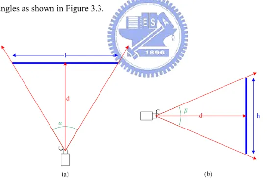
When a non-panoramic camera makes a projection on a plane, only a limited part of a scene can be imaged. The handiest parameter to describe the viewable area is the viewing angle, also called the field of view, of the camera. The horizontal viewing angle of a camera is the angle spanned from the left edge of the viewable region
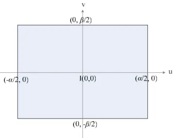
through the eyepoint to the right edge. The vertical viewing angle is the angle spanned from the top edge through the eyepoint to the bottom edge. As shown in Figure 3.2, we use α to denote the horizontal viewing angle and β the vertical viewing angle, of the camera. Each point in the image is formed by a different light ray through the optical center. As a result, each point in the image can be represented by two angles, the longitude and the latitude, of the light ray, described previously. In the image coordinate system, the u-axis has a longitude of 0o and the v-axis has a latitude of 0o. The latitude of the left edge of the image is –α/2 and the latitude of the right edge of the image is α/2. The longitude of the top edge of the image is β/2 and the longitude of the bottom edge of the image is –β/2. Then, each point in the image can be represented by a pair of longitude and latitude values in the range of the viewing angles as shown in Figure 3.3.
C
Figure 3.2 The viewing angles of the camera. (a) The horizontal viewing angle α. (b) The vertical viewing angle β.
Figure 3.3 An illustration of the image coordinate system confined by the ranges of the longitude and the latitude values.
3.1.3
Directional Angles of Camera
There are two kinds of directional angles of a camera. One is the pan angle and the other is the tilt angle. The pan angle of the camera is defined in the VCS and denoted by θc. It represents the degree of rotation of the camera and is important for
coordinate transformation.
We define the direction of the y-axis to be zero. The value of θc is exactly the
angular span between the camera direction and the direction of the y-axis. The range of θc is between 0 and π if θc is in the first and fourth quadrants and between 0 and –π,
else, as shown in Figure 3.4. The directional angle θc can be set as any value within
the range.
The tilt angle of the camera is defined by the angle between the optical axis of the camera and the ground. The angle, denoted as φc, represents the degree of tilting
of the camera. We define the angle to be zero when the optical axis of the camera is parallel to the ground. It is set to be zero at the beginning of a navigation session. The
range of φc is between 0 and π/2 if the direction of the camera tilts up and is between
0 and –π/2 else, as shown in Figure 3.5.
Figure 3.4 The pan angle of the camera. (a) 0≤θc ≤ (b) 0π ≥θc ≥ − π
Figure 3.5 The tilt angle of the camera. (a) 0
2 c π ϕ ≤ ≤ (b) 0 2 c π ϕ ≥ ≥ −
3.2 Review of Perspective Projection
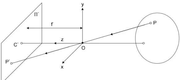
Perspective projection is a phenomenon conveyed by a classical pinhole camera. A pinhole camera coordinate system is shown in Figure 3.6. The vector plane, which
is formed by vectors x and y, is parallel to the image plane Π'. The point C' where it pierces Π' is called the image center, and the distance between C' and O is f'.
Let P denote a scene point with coordinates (x, y, z) and P' denote its image with coordinates (x', y'). Since the three points P, O, and P' are collinear, we get
' ' '
x y f
x = y = z ,
and so by the triangulation principle, we have ' ' , ' ' . x x f z y y f z ⎧ = ⎪⎪ ⎨ ⎪ = ⎪⎩ (3.1)
As shown in Figure 3.7, consider the fronto-parallel plane Π0 defined by z = z0. For any point P in Π0 we can rewrite the perspective projection Equation (3.1) as
' ' x mx y my = − ⎧ ⎨ = − ⎩ where 0 ' . f m z = −
The image center of Π0 is point C. Consider a point P in Π0, and its image P'. Let ( , )
CP= x y and ' ' ( ', ')C P = x y . From the mapping of the image coordinate system to the world coordinate system, it is impossible to figure out the distance between eyepoint and the point P due to the inherent ambiguity of the light ray projection. However, the point P', the projection of the point P, can be represented by the longitude and the latitude of the point P in the real world. For example, let the longitude and the latitude of the point P be θ and φ, respectively. Then the point P' can be presented as well by the pair of the longitude and the latitude (θ, φ), as shown in Figure 3.7.
Figure 3.6 Concept of perspective projection.
3.3
Calibration of Camera by Angular
Mapping
Each pixel in the image can be represented by a longitude value and a latitude value. With no camera distortion, each pair of longitude and latitude values is linearly mapped to a pixel in the image. It means that if we get a pixel P(u, v) in the image coordinate system, according to the linear mapping, we can get the longitude of P via
u and the latitude of P via v independently. Unfortunately, this assumption of no
camera distortion is ideal, and the coordinate transformation from the real world to the 2D image is nonlinear. We have to considerate the u-coordinate and the v-coordinate at the same time to get the longitude and latitude values of the pixel in the image. We will introduce the concept of a linear angular transformation which is the basic idea of the proposed calibration method described in Section 3.3.1. To correct the effect of the distortion, we will propose a nonlinear angular mapping method in Section 3.3.2.
3.3.1
Linear Angular Transformation
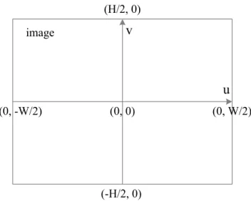
First of all, assume the swing angle of the camera is zero and the pan and tilt angles, α and β, of the camera are known. The horizontal and vertical resolutions, W and H, of the image are also known, as shown in Figure 3.8. We define the image coordinate system as shown in Figure 3.9. Assume also that the center of the imaging screen and the center of the lens coincide, i.e. the image coordinates (0, 0) specify the center of the image. Using the information mentioned before, we can define each pixel in the image coordinate system by the longitude and the latitude values. We use the vector (θ, φ) to represent the corresponding longitude and latitude pair of the pixel P(u, v) in the image. The detailed process of angular coordinate transformation is
described in the following algorithm.
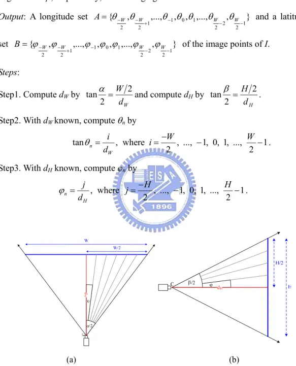
Algorithm 3.1 Angular coordinate transformation by trigonometric function.
Input: An image I with resolution W×H, and the horizontal and vertical viewing
angles α and β, respectively, of the imaging camera.
Output: A longitude set { , ,..., , , ,..., , }
1 2 2 2 1 0 1 1 2 2 − − − + − − = W W W W A θ θ θ θ θ θ θ and a latitude set { , ,..., , , ,..., , } 1 2 2 2 1 0 1 1 2 2 − − − + − − = W W W W
B ϕ ϕ ϕ ϕ ϕ ϕ ϕ of the image points of I.
Steps: Step1. Compute dW by W d W 2 2
tanα = and compute dH by
H d H 2
2
tanβ = . Step2. With dW known, compute θn by
tan , where , ..., 1, 0, 1, ..., 1 2 2 n W i W W i d θ = =− − − .
Step3. With dH known, compute φn by
, where , ..., 1, 0, 1, ..., 1 2 2 n H j H H j d ϕ = =− − − . (a) (b)
Figure 3.8 The relationship of image resolution and the viewing angles. (a) The horizontal direction. (b) The vertical direction.
(0, 0) (0, W/2) (0, -W/2) (H/2, 0) (-H/2, 0) image u v
Figure 3.9 An illustration of the image coordinate system confined by the ranges of image resolution.
3.3.2
Nonlinear Angular Mapping
With the camera distortion, the linear angular transformation method mentioned in Section 3.3.1 is not applicable to get the correct corresponding angles θi and ϕi of
the image coordinate system. To precisely obtain the angular transformation fromthe real world to the image, a real world data acquisition method by angular-mapping camera calibration is proposed. Since camera distortion exists both horizontally and vertically, we have to considerthe horizontal and vertical directions at the same time while we compute the longitude and latitude values of each point in the image.
In the proposed method, we attach a grid with m vertical lines and n horizontal lines on a wall which is perpendicular to the ground. Then we have a real world point set V = {V00, V01, …, Vmn}, where Vij = (θij, φij) is a pair of the longitude and latitude
values in the SCS of the point Vij at the intersection of the ith vertical line and the jth
horizontal line. The set V of intersection points is known in advance. And the corresponding point set P = {P00, P01, …, Pmn} appearing in the image may be
identified manually, where Pij = (uij, vij) is a point in the ICS corresponding to point Vij.
The detailed process of the previously-mentioned nonlinear angular mapping is described as an algorithm in the following.
Algorithm 3.2 The real location data acquisition by image taking and mapping. Input: An image I, as shown in Figure 3.11, and a set of longitude and latitude pair V
= {V00, V01, …, Vmn}, as mentioned above.
Output: A point set P = {P00, P01, …, Pmn} in I corresponding to V, with Pij
corresponding to Vij, where i = 0, 1, …, m and j = 0, 1, …, n.
Steps:
Step 1. Attach a grid with m vertical lines and n horizontal lines on a wall, which is perpendicular to the ground.
Step 2. According to the interval distance of the grid on the wall and the distance Dic
from the wall to the camera, measure the longitude and latitude values of each point Vij in the set V.
Step 3. Fix the interval of the longitude and the latitude to be 5º by adjusting the interval distance of each vertical line and each horizontal line of the grid on the wall based on the constraint of Dic = 170cm as shown in Figure 3.10.
Step 4. Mark yellow points at the intersections of the lines, as shown in Figure 3.11. Step 5. Record the coordinates of each yellow point Pij(uij, vij) in the ICS and group
all such points as a set P.
Step 6. For each point Pij in P in the image, manually identify the corresponding
point Vij in V with the longitude and latitude values θij and φij, as shown in
Figure 3.12 and set up the mapping.
other pixels in the image, we use an interpolation method, as described in the following algorithm.
Algorithm 3.3 Interpolation for computing viewing angles of any point.
Input: An image point I(u, v) in the ICS, the point set P and the point set V
mentioned in Algorithm 3.2.
Output: The longitude and latitude values VI(θI, φI) in the SCS of the image point I
in the ICS.
Steps:
Step 1. Compute the coefficients a and b of the line equation y = ax+b for lines L0,
L1, L2, and L3 by using the image coordinates of the four endpoints, Pij,
P(i+1)j, Pi(j+1), and P(i+1)(j+1) in the following ways, as illustrated in Figure 3.13, where we assume (u1, v1) and (u2, v2) are two endpoints of any of Li
with i = 0, 1, 2, 3: 2 1 2 1 1 2 2 1 2 1 ; . v v a u u v u v u b u u − = − × − × = −
Step 2. Decide whether the point I is in the region surrounded by the coordinates (u, v) of the four endpoints, Pij, P(i+1)j, Pi(j+1), and P(i+1)(j+1) by substituting (u, v) for (x, y) of the line equation in the following way:
0 0 2 2 1 1 3 3 ( ) ( ) 0; ( ) ( ) 0. a u b v a u b v a u b v a u b v ⋅ + − ⋅ ⋅ + − ≤ ⋅ + − ⋅ ⋅ + − ≤ (3.1) (3.2) If the inequalities (3.1) and (3.2) are satisfied, the point I is regarded to be in the region; else, repeat Step 2 to check the next region.
Step 3. Define a line Mh which passes the point I and its slope is the average of the
Mh with L0 and L2 as shown in Figure 3.13.
Step 4. Define a line Mv which passes the point I and its slope is the average of the
slope of L0 and L2, and so obtain two intersections s(us, vs) and t(ut, vt) as
shown in Figure 3.13.
Step 5. Use an interpolation method to obtain the longitude and the latitude (θI, φI)
of I in the SCS by the following equations according to the geometric ratio principle: ) , ( ) , ( 5 ) , ( ) , ( 5 t s d I t d r q d I q d ij I ij I × − = × + = ϕ ϕ θ θ
where d(a, b) is the distance from a to b.
By the interpolation method, each pixel in the image coordinate system can be mapped into the longitude and the latitude values in the SCS. By this information, we can get the angular position of objects in the image, as described in the following.
(a) (b)
Figure 3.11 A method of finding image coordinates of tessellated points in the grabbed image. (a) A grabbed image with tessellated points. (b) The tessellated points marked by yellow points.
Figure 3.12 The points on the wall corresponding to of yellow points in Figure 3.11(b).
Pij Pi(j+1) P(i+1)j P(i+1)(j+1) L0 L1 L2 L3 t s r q Mh I Mv
Figure 3.13 An illustrate of the interpolation method that a region contains the point
I in the ICS.
3.4 Vehicle Location Techniques Using
Angular Mapping
Using the calibration by the non-linear angular mapping method mentioned in Section 3.3.2, we can get the longitude and the latitude values of each pixel in the image. Since the camera is equipped on the arm of the vehicle, the directional angles of the camera are not always zero. When the pan angle of the camera is not zero, the directions of an object with respect to the camera and the vehicle also are both different. To track the target object correctly, we have to transform the directional angles with respect to the camera to ones with respect to the vehicle. In order to obtain the transformation, the information of the longitude and latitude values which are obtained from mapping the image coordinates is not enough. We must have more data to solve the ambiguity in distance estimation.
First, we have to know how to calculate the distance between the object and the camera by the latitude value and the distance from the camera to the ground, and we will discuss our method for this purpose in Section 3.4.1. And the way we propose for computing the directional angles of the camera with respect to the vehicle will be stated in Section 3.4.2.
3.4.1
2D to 3D Distance Transformation
As shown in Figure 3.14, we knew the coordinates of an object in the ICS after we take the image of the object. After the angular mapping, we have the information of the longitude and the latitude of each image point of the object in the SCS. Since we have the latitude value of the object and the knowledge about the height of the camera, if we know the ground contact point of the object in the image, we can compute the distance between the camera and the object. The algorithm is described in the following.
Algorithm 3.4 Transformation of 2D image point to 3D real world point.
Input: Camera height Hc, and the ground contact point P(u, v) in the ICS of an object.
Output: The distance Doc between the object and the camera.
Steps:
Step 1. Transform (u, v) of P into its (θ, φ), the longitude and the latitude in the SCS, by the proposed mapping method described in Section 3.3.2.
Step 2. Compute Doc by the following equation:
OC c c D H = − ) tan(ϕ ϕ
Since we know the distance between the vehicle and the object by applying the above algorithm, what we have to do now is to turn the direction of the vehicle toward the object and moves forward. The way we propose to find the angle the vehicle has to turn will be introduced in the next section.
(a)
(b)
Figure 3.14 The distance between the object and the vehicle. (a) The camera has no tilting, i.e. φc = 0. (b) The camera has a tilt angle of φc.
3.4.2 Angle Transformation between Coordinate
Systems
As shown in Figure 3.15, we can know the point of the object in the image and get the distance from the vehicle to the object according to the above algorithms. However, the rotation center of the camera is different from the one of the vehicle.
angle θv, the angle that the vehicle has to turn to aim at the object, in the PCS. The
transformation from (u, v) in the ICS to θv in the PCS is described in the following
algorithm.
Algorithm 3.5 The angular transformation from the ICS to the PCS.
Input: The distance between the rotation center of the camera and the vehicle, and
the ground contact point (u, v) of the object in the ICS.
Output: The directional angle θv of the object in the PCS
Steps:
Step 1. Transform (u, v) to (θ, φ), the longitude and latitude in the SCS, by the proposed mapping method in Section 3.3.2.
Step 2. Compute θv in the PCS by the following equation according to Figure 3.15:
cv oc oc v D D D + ⋅ ⋅ = θ θ θ cos sin tan .
Figure 3.15 The rotation angle of the vehicle to obtain the tracking of the object.
From the above algorithm and the one in the last section, we can transform the position of the object in the image to the polar coordinate system with the distance and directional angles (Dic, θv). By the transformation, the location of an object in the
Chapter 4
Human Detection by Image Analysis
for Indoor Security Patrolling
4.1 Overview of Human Detection
There are many kinds of features and sensors to detect human beings. Since visual perception is the only sensing capability of the proposed system in this study, image analysis is one of the solutions to detect human beings. The face is an obvious characteristic of human beings. As the result, we propose a method to detect human faces by color and shape features in images. The method for face detection will be described in Section4.3. Sometimes, the limitation of camera resolution makes the acquired image unclear. A far distance from a person to the camera might cause difficulty in segmenting a clear human face region out of an image of the person. To redeem the limitation, we propose a blockwise frame difference method to extract moving objects in the image and decide if the moving object is similar to a human body. The motion detection method will be proposed in Section 1.4. Before all the details of the mentioned techniques are described, we will give a brief introduce to the proposed process in Section 4.2 first.
4.2 Proposed Process of Human
Detection
The proposed process of human detection has two major parts: human face detection and human body detection. The features we adopt to detect a human face are color and shape. The color of the face undoubtedly is just the skin color, and the skin color has been studied intensively in recent years. In this study, we adopt an elliptic skin model to determine if the color of a pixel is skin color or not.
After getting all the skin color regions in an image, we have to recognize which one is similar to the shape of a human face. As the contour of a human face is roughly elliptic in shape, we propose a method for matching each skin color region with an elliptic shape mask. On the other hand, to avoid erroneously recognizing an elliptic non-face region as a face from skin color regions, we make a double check by motion detection.
If nothing is detected by the face detection process, we decide that a person might exist at a far distance. Then, we try to confirm the decision further by detecting the existence of a human body using moving regions in the image, which can be obtained by an additional process of frame differencing. The technique of frame differencing does not work finding the case of having a moving region in a changing background. We propose therefore a blockwise frame differencing technique to detect moving regions. After performing this technique, we can get moving regions in an image and detect any human body by applying a shape recognition technique to these moving regions.
The system will stop the human detection process and start a human tracking process as long as a face is detected in an image. The process of human tracking will
be described in the next chapter. The major steps of the proposed process of human detection are presented as follows.
Step 1. Capture an image.
Step 2. Apply region segmentation by skin color identification and motion detection by blockwise frame differencing to extract motion regions. Step 3. Fit each extracted skin region with an ellipse to detect a possible
human face.
Step 4. Apply human body detection by applying shape recognition to extracted motion regions.
The proposed process of human detection is illustrated in Figure 4.1.
Human Detection Face Detection Body Detection Skin Segmentation Ellipse Fitting Blockwise Frame Difference
Shape Color Motion
yes yes
Face Detected? no Body Detected?
Finish VehicleMoves
no Image
Captured
4.3 Human Detection by Faces
In order to detect faces in images, we have to choose features to define a face. The features we used in this study are color and shape, as mentioned previously. The rough sketch of a face can be represented by the shape of an ellipse with the skin color. Thus, we detect a human face in the image by searching a skin-colored ellipse.
More specifically, recognizing a skin-colored ellipse in an image needs two tasks: giving the definition of skin color and conducting pattern recognition of ellipses. With a captured image, we first segment out any skin region and then fit shapes to the regions. If a skin color region is close to an ellipse in shape, it is decided that a face is detected. In Section 4.3.1, we will introduce the proposed method of classification of skin color. And in Section 4.3.2, we will describe the proposed method for ellipse shape recognition.
4.3.1 Skin Region Segmentation Using Color
Classification
Skin region segmentation is commonly used for face detection. Determining a color pixel is of a skin color or not is the goal. Before defining the classifier for skin color, the choice of color representations is important, which affects the complexity of the classifier. In this section, we describe the color space and the classification algorithm proposed in this study.
4.3.1.1 YC
bC
rColor Space
Many common color models are used in the field of computer vision, for examples, RGB, HIS, HSV, YCbCr, CMY, CIE, etc. Each one of the color models has its own characteristics and is applicable to a specific set of applications. In the
application of skin region segmentation, classifiers for different color models are proposed in many research works.
In this study, we choose the YCbCr to be the color space for detecting skin color in images. According to Chai and Bouzerdoum [20], the distribution of skin color in YCbCr color space is concentrative and the distribution of the skin colors of different human races are similar. As the result, transforming images in the RGB color space into ones in the YCbCr color space can reduce the complexity of skin-color pixel classification.
In the YCbCr color space, Y represents the luminance, Cb represents the chrominance of blueness, and Cr represents the chrominance of redness. Y is coded from 16 to 235, where code 16 is black and 235 is white. And Cb and Cr range from 16 to 240. RGB values can be transformed into the YCbCr color space by (4.1) below:
b r Y 16 65.481 128.533 24.966 R C 128 37.797 74.203 112 G C 128 112 93.786 84.214 B ⎡ ⎤ ⎡ ⎤ ⎡ ⎤ ⎡ ⎤ ⎢ ⎥ ⎢= ⎥ ⎢+ − − ⎥ ⎢ ⎥ ⎢ ⎥ ⎢ ⎥ ⎢ ⎥ ⎢ ⎥ ⎢ ⎥ ⎢ ⎥ ⎢ − − ⎥ ⎢ ⎥ ⎣ ⎦ ⎣ ⎦ ⎣ ⎦ ⎣ ⎦ (4.1)
Given the input RGB values which are within the range of [0, 1], the output values will be within the range of [16, 235] for Y and [16,240] for Cb and Cr.
Figure 4.2 shows the YCbCr color model with the value of Y being 126. Because the transformation from the RGB space to the YCbCr is linear but not one-to-one, some value sets of Cb and Cr are not meaningful when the value of Y is 126. Some YCbCr color models with different Y values are shown in Figure 4.3. When Y is 16 which is the darkest luminance, Cb and Cr can only have the value of 128. Likewise, when Y is 235 which is the brightest luminance, Cb and Cr also only have the value of 128. Figure 4.4 shows a 3D YCbCr color model [23][24].
Cb Cr (65, 48) (190, 207) Y=126 16 240 16 240
Figure 4.2 YCbCr color model with Y = 126
Figure 4.4 3D YCbCr color model in [23][24].
4.3.1.2 Adopted Skin Color Model
Previous studies have found that pixels belonging to skin regions exhibit similar Cb and Cr values [20][21]. Chai and Mgan [21] used a fixed-range skin color map in the Cb-Cr plane for face segmentation, and the range of Cb is between 77 and 127 and the range of Cr is between 133 and 173. And the region of the skin color is shown to be a rectangle. However, when we observe the distribution of skin color in the Cb-Cr plane, it is found more similar to an oblique ellipse, as shown in Figure 4.5. In the study by Lee and Yoo [22], a new statistical color model for skin detection with elliptical boundaries was suggested. Thus, we define an oblique ellipse in the Cb-Cr plane to be the skin color model in this study, and the parameters of the elliptic skin model are adjusted by experiments. The center of the elliptic model is taken to have the values 103 for Cb and 158 for Cr. And the angle of rotation is set to be 145 degrees, and the lengths of major and minor axes are set to be 25.39 and 14.03 respectively.
Figure 4.5 Distribution of conditional probability density function of skin color in Cb-Cr plane [20].
Figure 4.6 The elliptic skin model used in this study.
4.3.2 Detection of Human Face by Ellipse Shape
Fitting
Since the shape of a human face is close to an ellipse, we propose in this study a pattern recognition method for ellipse shape detection to distinguish face regions from
other skin regions segmented out by the skin color classification mentioned in Section 4.3.1. More specifically, after segmenting the skin color regions out of an image, we determine if the region is similar to an ellipse. If so, we take it to be a human face. The method to decide whether a region is elliptic in shape is described as an algorithm in the following.
Algorithm 4.1 Face detection by pattern recognition of ellipses.
Input: A skin region set R=
{
R R1, 2,...,Rn}
as shown in Figure 4.7(b). The width of a region Ri in R is denoted by wi, and the height of Ri by hi. The boundaries ofthe region Ri are denoted as lefti, righti, topi, buttomi. And the number of
pixels in region Ri is denoted by pi.
Output: A face region Rface.
Steps:
Step 1. Get a new skin region R' by
i ' { i 1 and , 1, 2,..., } i i w h R = R ≤ p >c ∀ =i n
where c is a pre-selected constant.
Step 2. Make a rectangular mask rectanglei for Ri with width wi and height 1.2×wi,
and an elliptic mask ellipsei for Ri with its major axis length being wi and its
minor axis length being 1.2× , as shown in Figure 4.7(c). wi
Step 3. To fit each region in R' with an ellipse shape, compute the number, ini, of the
pixels of region Ri within ellipsei. Additionally, compute the number, outi, of
the pixels of region Ri within rectanglei and without ellipsei. That is,
,
( ),
i i i i
i i i i i
in R ellipse R R'
out R rectangle ellipse R R'
= ∀ ∈
= − ∀ ∈
∩ ∩
Step 4. Calculate a score Si for each skin region Ri in R' by
i i i
S =in −out . Step 5. Normalize Si into the range [0, 1] by
area of i i i S S ' ellipse = .
Step 6. Decide region Ri to be a face region Rface if the score Si' of Ri is highest
among all regions in R and Si' is higher than a threshold h in the range of [0,
1] which is defined in advance.
By the ellipse shape fitting as described above, we can detect the face region in images, as shown by the example in Figure 4.7.
(a) (b)
(c) (d)
Figure 4.7 The detection of human face by ellipse shape fitting. (a) Input image. (b) Skin Segmentation. (c) Rectangular and elliptic mask. (d) Detected face region.
4.4 Human Body Detection by Motion
Analysis
Two kinds of misjudgments happen in the human detection work using the proposed human face detection method mentioned in the last section. One is recognizing a face-like object to be a human face in the image, and the other is detecting nothing when a person does exist at a distance from the vehicle. To avoid the first kind of mistake, we need an advanced feature to confirm if the detected face region is a human face or not. Also, to avoid the second type of mistake, we have to detect humans by other features, not only the feature of face. In this study, we use techniques of motion detection and human body recognition to reduce the effects of these drawbacks and so increase the reliability of the proposed system.
In a fixed camera system, the moving parts of the scene can be detected by frame differencing with fixed backgrounds learned in advanced. Unfortunately, this method is not working in our system because the background in the image is always changing with the camera on the moving vehicle and robot arm. We thus propose in this study a method of frame differencing for use by our vehicle system, which is presented in Section 4.4.1. In Section 4.4.2, we will describe the method of human body recognition by motion detection.
4.4.1 Motion Detection by Shift Tolerance Blockwise
Frame Differencing
First, we define some terns for use in the proposed method.
(1) Current image: The image captured from the camera at the current moment or equivalently in the current navigation cycle.
(2) Reference image: The image captured from the camera at the last moment.
(3) Block: A block consists of a square region of pixels, which is the unit of the image. (4) Searching window: A searching window consists of a square region of pixels,
whose size is larger than the size of a block.
Subtracting the current image from the reference image block by block is the basic idea of blockwise frame difference. If the difference between the target block in the current image and the candidate block at the same position in the reference image is below some threshold, then it is may be considered that no motion has taken place, i.e. the target block is stationary. If it is not, we will find the best match block for the target block within the searching window in the reference image. If the best match block is below the threshold, we say that the target block is stationary; otherwise,
moving. Repeating these steps for each block in the current image, we can get all the
moving parts in the current image. The detail is stated in the following algorithm.
Algorithm 4.2 Shift tolerance blockwise frame differencing.
Input: current image Ic, reference image Ir, block size s s× , and the size of a
searching range w, which makes the size of the searching window being (2w s+ ×) (2w s+ . )
Output: a difference image Id.
Steps:
Step 1. Segment Ic into a block set
{
11, 12,..., 1 , 21, 22,..., 2 ,..., 1, 2,...,}
c m m n n nm
B = b b b b b b b b b ,
where the size of B is m n× as shown in Figure 4.8. Also, segment Id into
a block set Bd in the same way.
in Figure 4.9. Subtract the target block bij from the candidate block at the
same position in the reference image. If the difference is below the threshold t, regard the target block bij as stationary and go to Step 5.
Otherwise, go to Step 3.
Step 3. Find the best match block of the target block bij within the searching
window in the reference image by subtracting the target block bij from each
of the blocks within the searching window, as shown in Figure 4.10. Step 4. If the difference between the target block bij and the best match block is
below the threshold t, regard the block bij as stationary; else, moving.
Step 5. Repeat Step 2 for each block in Bc to decide the state, stationary or
moving, of it.
Step 6. Get a complete frame difference image Id by filling the moving blocks with
white color and the stationary blocks with black color, as shown in Figure 4.11.
current image Ic reference image Ir s s bij w w w w s s searching window 2w+s 2w+s bij searching window
Figure 4.9 The searching window.
Figure 4.11 An example of blockwise frame difference images.
4.4.2 Human Body Detection
By the blockwise frame differencing result obtained by the method described in the last section, we can get a difference image from every two sequential image frames. The difference image shows the moving regions at the current moment. Since we compute the moving regions by blockwise frame differencing instead of a pixelwise operation, the regions do not appear to have a complete shape of a human body. Moreover, the shape of a human body is irregular in shape, so it is impossible to detect a human body by fitting a detected region with a certain well-known shape.
Furthermore, when the vehicle is moving in an open space, if the system detects some moving regions, we can assume that there is something moving in the filed of view of the camera. Since the shape of a human body is complicated and is hard to define, we use only the ratio of the width to the length of a moving region as a feature for human body detection in this study. This feature of a normal person is defined to be the ratio of the shoulder width to the body height. And a reference range of this ratio is around 1/4 as shown by the Vitruvian Man painted by Leonardo da Vinci. However, if two sequential images both include the same person but at different positions, the difference of these two images cannot form a complete shape of a