aCorresponding author: [email protected]
Flexible Manufacturing Systems and Computer-Integrated Manufacturing
Johannes K. Chiang1 and Kiekang Chao21National Chengchi University, Management Information System Department, 11605 Taipei City, Taiwan 2National Chengchi University, Management Information System Department, 11605 Taipei City, Taiwan
Abstract. Since decades, Flexible Manufacturing System (FMS) is a significant part of automated production and
manufacturing. In the development of FMS, deadlock prevention becomes a crucial point. This paper present a critical-siphon theory to demonstrate exactly one monitor for quality FMS is required for the set of critical-siphons in the family of a 2-compound siphons and how to assign its initial markings. The theory is aiming to avoid redundant monitors in FMS and the unnecessary associated computational burden so that the quality of a class of Flexible Manufacturing Systems can be assured latest in the run-time. Neither reachability graph nor minimal siphon needs to be computed achieving polynomial complexity- essential for large systems. This paper redevelops the theory more formally and further applies this approach to two well-known S3
PR to obtain a controller full or near maximally permissive in the context of deadlock resolution and Quality Assurance. This paper further categorizes mixture siphons into partial and full ones and the sequence among them to add monitors associated with one or different 2-compound siphons. As a result, there is no need to enumerate all siphons and the time complexity involved is polynomial. This is the first of its kind of works among all current results on the benchmark.
Introduction
After the concept of Build-to-Order, FMS becomes the most important component of automated production and manufacturing. Deadlock-freeness is essential for the automation of a FMS as well as a CIM. Various deadlock resolution approaches [1, 2] have been proposed to tackle deadlocks. Deadlock prevention has been popular to avoid deadlocks in FMS and CIM since it runs fast and statically to avoid run-time detection and computation. Classical approaches either suffer from adding too many monitors or reaching too few states [1,2,3]. Recently, maximally permissive process control policies [4,5,6] with little redundancy have emerged. They however suffer from either complete state enumeration—based on region theory [4,5,6] or the concept of selective-siphons [6]. Both are NP-hard and take exponential amount of time.
In obtaining PN based monitors for deadlock prevention (or liveness enforcing) there are three main issues tackled within the literature: behavioral permissiveness, computational complexity, and structural complexity. Behavioral complexity is related to the performance in terms of the reachable good states. In the context of FMS the number of good states in a Petri net model of an FMS, which can be provided under the deadlock prevention or liveness-enforcing policies, has been regarded as a “quality measure”. In terms of the practical implementation of these policies, this quality
measure implies high efficiency, throughput, and flexibility [3]. The highest quality can be provided by the maximally permissive (optimal) control policies. Computational complexity is related to the computational cost paid in order to obtain a liveness-enforcing supervisor (LES) for a given deadlock prevention FMS problem. In this case it is desirable to obtain an answer for a given problem in the least time possible. Structural complexity means extra cost in system verification, validation, and implementation. It is related with two aspects of a LES: the number of monitors and the type of monitors. In the former, it is desirable to obtain the least number of monitors possible. In the latter, there are two types of monitors: ordinary and general. Ordinary monitors are the ones with no weighted arcs. General monitors are the ones with weighted arcs. It is obvious that ordinary monitors are preferable to general monitors due to verification, validation, and implementation issues.
Classical approaches either suffer from adding too many monitors [4] (problematic siphons growing quickly with the size of the system) or reaching too few states [5, 6]. Recently, maximally permissive control policies [7-11] with little redundancy have emerged. They however suffer from either complete state enumeration—based on region theory [7-11] or the concept of selective-siphons [10, 11]. Both are NP-hard and take exponential amount of time.
We propose in [12] to optimize the number of monitors (good states as well) if one adds monitors in the normal
sequence of basic, compound, control, and other types of siphons. It is shown that among all 2-dependent siphons (depending on two component siphons), only one (called critical) siphon needs to be controlled by adding a monitor. This greatly simplifies the synthesis as well as minimizes the number of monitors required while making the controlled net near maximally permissive. Furthermore, the computational burden is much less since there is no need to enumerate minimal siphons, nor to build the reachability graph. It requires neither iterations nor the removal of redundant monitors. In addition, no control arcs are weighted. It scales well with the initial markings and the size of the nets. However, theorems in [12] are stated and proved based on non-formal concepts and symbols.
This paper redevelops the theorems more formally by defining some new symbols so as to be able to show that for all the emptiable siphons derived from a 2-compound siphon, only one monitor is required. This paper further categorizes mixture siphons into partial and full ones and the sequence among them to add monitors associated with a or different 2-compound siphons. As a result, there is no need to enumerate all siphons and the time complexity involved is polynomial. We apply the above theory of sequence-control or critical-siphon to the control of 2 well-known benchmarks with much less computational burden than other approaches, while achieving near or full maximal permissiveness. This is the first paper that is able to identify that each monitored siphon of the benchmark is either a basic one, or a compound one, or a mixture one. This is the first of its kind among all current results on the benchmark.
The rest of the paper is organized as follows. Section II presents the preliminaries about types of siphons. Section II reviews the dependence relationship as well as the sequence of control to reduce the number of redundant monitors. It also develops new theories. Section III applies the theory to 2 well-known benchmarks. Finally, Section IV concludes the paper.
Theory
Due to the space limitation, we refer the reader to [12] for some basic terminologies in this paper. A core subnet can be obtained from an elementary circuit, called core circuit, by repeatedly adding handles. Details of handles and how an SMS is synthesized from a core subnet are in [8, 12, 13] and omitted here to shorten the paper.
Theorem 1 (Theorem 1 in [20]): Let (N0, M0) be a
marked S3PR and S
1, S2,... , Sn. a set of SMS such that ∀i∈
{1,2, …,n}, Si∩Sj≠∅ if |i – j|=1 and Si is controlled (M(Si)>0). Each Si is a basic siphon synthesized from basic circuit ci. S0 is an SMS synthesized from c0= c1 o c2
o…ocn and R(S0)= R(S1)∪R(S2)∪ …∪R(Sn) (R(S) is the set
of resource places in S). c0 and S0 are called an
n-compound circuit and siphon respectively. Let Si∩[S0]=Ai
∀i∈{1,2, …,n-1}. Then, (1) if ∃M∈R(N,M0), such that
M(S0)=0, then M(A1)+ M(A2)+…+ M(An)≥n. (2)
∀M’∈R(N,M0), M’(S0)>0, if M0(Si ∩Si+1)=1,∀i∈
{1,2, …,n-1}.
Figure 1(a). Example partial-mixture. Figure. 1(b) Controlled
model siphon.
In Fig. 1(a), there are three SMS: S1={p3, p4, p7, p11, p12,
p16}, [S1]= [VS1] ={p2, p8, p9}, S2 =}p5, p9, p12, p13}, [S2]=
[VS2] ={p3, p4, p10}, and S0= S3= S1,2m = {p9, p10, p6, p11, p4}.
R(S3)= {p9, p10, p11}⇒R(S3)= R(S1)∪R(S2). S1 and S2 (resp.
S0) are basic (resp. compound) siphons; both are controlled
since M0(VS1)= M0(p14)=2 and M0(VS2)= M0(p15)=2.
M0(S0)=3 and A1= S1∩[S0]={p4}, A2=S2∩[S0]={p9},
A1∪A2={p4, p9}=H(p12)=H(S1∩S2). Thus, S0 is controlled
(no need for control elements) if b=M0(S1∩S2)= M0(p12)=1.
On the other hand, if b>1, we need to add control elements for S0 to be controlled.
In Fig. 1(b) (controlled model of that in Fig. 1(a)), S1={p3, p4, p7, p11, p12, p16}, [S1]= [VS1] ={p2, p8, p9}, S2 ={p5, p9, p12, p13}, [S2]= [VS2] ={p3, p4, p10}, and S3= S1,2m = {p3, p5, p7, p11, p12, p13, p16}, S1,2c ={p3, p4, p8, p9, p15, p14}, [S1,2 c] ={p2, p10}, b=M0(p12)=1. R(S1,2m)= R(S1,2c)={p11, p12, p13, p16}, R12={p16}, R22=Ø, R13={p11}, and R23={p13}. Furthermore, [S1,2 p]={p2, p8, p9, p10}=[S1,2c]∪[VS1], [S2,1 p]={p2, p3, p4, p10}=[S1,2c]∪[VS2], [S1,2m]= [S1,2f]={p2, p4, p8, p9, p10}, [S1,2p]⊂[S1,2m], [S1,2f]=[S1,2m], and R([S1,2c])=
R3=R13∪R23 as in the following lemma.
In Fig. 2, R1 2={p12}, R22={p10}, R13=R([S1,2c] ∩[S1])={p7, p8} and R23=R([S1,2c]∩ [S2])={p11, p13}. Mmax([S1,2c])=M0(R3)=M0(p7)+M0(p8)+M0(p11)+M0(p13) =a+c+d+g. (1) M0(VS1)=[M0(R12∪R13)+M0(R1)-1]=a+d+e+b-1. (2) M0(VS2)=[M0(R22∪R23)+M0(R1)-1]=c+g+f+b-1. (3) M0(VS1)+M0(VS2 )=a+c+d+e+f+g+2(b-1)>Mmax([S]). (4)
Thus, S cannot become unmarked. Based on this theorem, one adds a monitor for a control siphon only if there are no non-sharing resource places (R1
2=R22=Ø) in
the two basic siphons and the initial marking of S1∩S2
equals one. For the example in Fig. 1(b), even if b=1, no monitor is needed for the control siphon due to the presence of non-sharing resource place p16. For the
example in Fig. 1(b), b=1, R1
2= { p16}≠Ø (see the
example after Def. 4), S1,2
c = {p3, p4, p8, p9, p14, p15},
siphon can never become unmarked since p14∈ S1,2c and
p8∈ S1,2c.
Theorem 2: If S=S1,2
c can become unmarked, and is
controlled by adding a monitor, then any mixture siphon, partial or full, corresponding to compound siphon S1,2
m, is
already controlled and needs no monitor.
This theorem states that all mixture siphons are already controlled and need no monitors after I add a monitor upon the control siphon. If one follows [14] to add a monitor with WC arcs for the mixture siphon, the monitor is redundant. In Fig. 2, the control siphon S can become unmarked if b=1. For S’=S1,2
p, A= H(R13) ∩ [S’]={p2},
ρ(R1
3)= {p6, r1=p9}, ρ(R13)\A={p6, r1=p9}. After
adding a monitor for S so that M([S])< M0(R3)=a+c, S’ may
become unmarked only if M(p2)=a-1. This sets M(ρ
(R1
3)\A)=1 or M(S’)=1. Hence, S’ is already controlled.
Similar conclusion applies to S’=S1,2
p. For S’=S1,2f, either
Mmax(A1)= M0(R13) – 1, or Mmax(A2)= M0(R23) – 1. In either
case, it is easy to see that S’ is already controlled.
Figure 2. Example full-mixture siphon and non-redundant WC.
Theorem 3: Let S=S1,2
p be a partial mixture siphon as
defined in Def. 10, and no monitor is added for S1,2 c. 1)
Mmax([S]) =M0(R12∪R3)+ b-1. 2) S can become unmarked,
if i) R2
2=Ø. ii) b= M0(S1∩S2)=1. 3) S becomes unmarked
when Mmax([S]) = M0(R12∪R3)+ b-1= M0(VS1)+ M0(VS2)=
[M0(R12∪R13)+ M0(R1)-1]+ [M0(R22∪R23)+ M0(R1)-1]=
M0(R1∪R2∪R3)+ b-2, Simplifying the algebra, we have
M0(R22)+ b-1=0, which implies R22=Ø, and b=
M0(S1∩S2)=1. Thus, S can become unmarked if R22=Ø, and
b= M0(S1∩S2)=1.
This theorem states that if no monitor is added for a control siphon, then a monitor is needed for partial mixture siphon S1,2
p if b= M0(S1∩S2)=1 and there are no
non-sharing resource places (in S2) whose holder places are in
[S2]. For the example in Fig. 1(b), b=1, R22=Ø (see the
example after Def. 4), S1,2
p = {p3, p4, p7, p11, p14, p15}
and [S1,2
p]={p2, p8, p9, p10}. S1,2p is unmarked when
M(p8)= M(p9)=1 and M(p10)=M(p2)=2 even though there
exists non-sharing resource place p16. If one follows [14]
to add a monitor with WC arcs for the partial mixture
siphon, the monitor is not redundant. We now extend the theory to full mixture siphons.
Theorem 4: Let S=S1,2
f be a full mixture siphon
corresponding to compound siphon S1,2
m. Then 1) Mmax([S])
=M0(R1∪R2∪R3)+ b-2. 2) S can never become unmarked if
b>2. 3) S can become unmarked in the normal sequence, if i) R1
2≠Ø and R22≠Ø; and ii) b= M0(S1∩S2)=1.
From Part 1 of this theorem, if S becomes unmarked, then Mmax([S]) = M0(R1∪R2∪R3)+ b-2= M0(R1∪R2∪R3)=
M0(R([S1,2m])) since b=2 against the fact that Mmax([S])=
M0(R([S1,2m])) – 1 derived earlier. Thus, S can never
become unmarked if b=2. Hence it must be that b=1. Assume that it does not hold that R1
2≠Ø and R22≠Ø. There
are two cases: i) R1
2= R22=Ø. S1,2c is not controlled since Condition 1
(R1
2=R22=Ø) in Theorem 2 is satisfied and b=1. Adding a
monitor to S1,2
c leads to the inequality M([S1,2c])< M0(R3),
which implies that M(H(R3) ∩S)+ M(R3)>0⇒M(S)>0.
ii) Exactly one of R1
2 and R22 is a nonempty set. By
Theorem 2, a monitor is added for a partial mixture S’ siphon such that M([S’]) cannot reach its maximum for S’ to become unmarked, neither can [S] since [S’]⊃[S] by Parts 2 and 3 of Lemma 1. Hence S cannot become unmarked. Both Cases i) and ii) contradict the assumption that S can become unmarked. Thus, if S can become unmarked, then b=1, R1
2≠Ø and R22≠Ø. If b=1. From Part
1 of this theorem, if S becomes unmarked, then Mmax([S])
= M0(R1∪R2∪R3)+ b-2= M0(R1∪R2∪R3) -1 which is
feasible since Mmax([S])<M0(R[S1,2m]) (no monitor for S1,2m
by Theorem 1). Furthermore, by Theorem 2, S1,2 c is
controlled (with no monitor) since R1
2≠Ø and R22≠Ø
implies that Condition 1 (R1
2=R22=Ø) in Theorem 2 does
not hold. Thus, it is possible that M([S1,2c])= M
0(R3) (since
no monitor for S1,2
c) and Mmax([S]) =M0(VS1)+ M0(VS2) (i.e.,
S can become unmarked), which is not possible if a monitor was added for S1,2
c. This theorem states that a full
mixture siphon S can become unmarked if and only if b=1 and there are non-sharing resources in both R1
2 and R22.
Note that if one of R1
2 and R22 is empty, then by Theorem
2, a monitor is added for a partial mixture siphon, which causes the complementary set of S not to reach its maximum.
Hence, S cannot become unmarked. For the example in Fig. 2, R1
2={p12}≠Ø and R22={p10}≠Ø. S1={p7, p8, p9, p12,
p4, p’2}, [S1] = {p2, p3, p’3, p’4}; S2= {p9, p10, p11, p13,, p6,
p’4}, [S2] = {p4, p5, p’5, p’6}; S3= S1,2m = {p7, p8, p9, p10, p11,
p12, p13, p6, p’2}, [S3] = {p2, p3, p4, p5, p’3, p’4, p’5, p’6}. S1
and S2 (resp. S3) are basic (resp. compound) siphons.
S1,2
f={VS1, VS2, p7, p8, p11, p13, p6, p’2}can become
unmarked when b=1 and monitors are added only for basic siphons. If one follows [14] to add a monitor with WC arcs for the full mixture siphon, the monitor is not redundant. No monitors are needed for the compound, control and partial mixture siphons. The following theorem guides us on how to add a monitor to a control or a mixture siphon.
Theorem 5: Let VSi be the monitor added upon Si, i=1
or 2, such that Si is controlled and S be a relevant control,
or mixture, or full, or partial, unmarked siphon. A monitor V is added upon S such that [V]=[S] and M0(V)= M0(VS1)+
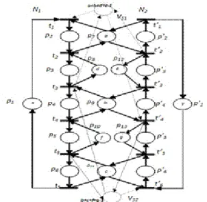
For the example in Fig. 3, partial mixture siphon S=S1,2
p = {p3, p4, p7, p11, p14, p15} may become unmarked
when b=1 in the normal sequence. S becomes controlled by adding monitor V such that [V]=[S]={p2, p8, p9, p10}
(i.e., V●={t1, t10}, ●V={t2, t7}) and M0(V)= M0(VS1)+
M0(VS2)-1= M0(p14)+ M0(p15)-1=3+2-1=4. As mentioned
earlier, the compound, and the control siphon, and S=S2,1 p
are all controlled and need no monitor. Only three (two for basic siphons and one for S1,2
p) monitors are needed to
control the net to make it live.
Figure 3. First benchmark example.
For the example in Fig. 2, S=S1,2
f can become
unmarked when b=1 and monitors are added only for two basic siphons. S becomes controlled by adding monitor V such that [V]=[S]={p2, p3, p4 p5, p’3, p’4, p’5, p’6} (i.e.,
V●= { t1, t’6} , ●V= { t’2, t5} ) and M0(V)= M0(VS1)+
M0(VS2)-1= (a+b+d+e-1)+ (b+c+f+g-1)-1. Only three
monitors are needed to control the net to make it live. For both examples, there is no need to add WC places
Theorem 6: Let S3 =S1 o S2 in a marked S3PR (N0, M0),
Si (i=1 or 2) is controlled by adding monitor VSi, S1∩S2={r}.
Then exactly one siphon in the set of the compound siphon, control siphon and all mixture siphons is emptiable.
Remarks: The resulting controlled model may not be maximally permissive since some live states are forbidden. For instance, in Fig. 1(b), M=2p10+p9+p8+p11 or
2p10+p9+p8+p7 (as common practice, only operation places
are included in M) is a live marking, yet forbidden by Monitor p17. However, if a monitor is added for each M to
control smaller region of operation places (hence less disturbance to the original model), the controlled model becomes maximally permissive. We call {p8, p9} a
refinement region. If a single monitor is added to cover a refinement region, some live states are lost. If for each place in a refinement region, a monitor is added accordingly (called refine operation), then no live states are lost. For the two examples in the next section, refine operations will be performed to reach more live states.
Applications
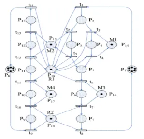
This section applies the developed theory to two well-known S3PR. For example in Fig. 4, however, needs WC
arcs to be maximally permissive. We add a monitor for each basic siphon. Among 12 compound siphons, We need only add one monitor for S15 (b=2) (Theorem 1)
significantly reducing the total number of monitors required. For the rest of compound siphons, we have b=1. Now consider 3-compound siphon Sijk=Si o Sj o Sk= Sij o Sk.
Based on Theorem 1, all 3-compound siphons are not controlled. However, this ignores the fact that all 2-compound siphons have been controlled. Note that Sij∩Sk=
{r} and b=M0(r) =1 for all 3-compound siphons. Thus,
by Theorem 1, they are all controlled and needs no monitor. In summary, there are only two 2-control siphons S’20
and S’22 with no monitors for both the associated
compound and control siphons. This implies that one of the associated mixture siphons (Theorem 4) is emptiable and needs a monitor.
Now consider adding monitors for mixture siphons. By Theorem 4, no monitors need to be added for mixture siphons built from control siphon S19 since a control
monitor has been added for S19. By Theorem 2, no
monitors need to be added for any partial mixture siphon S built from control siphon S20 since b= M0(S1∩S16)>1 and S
can never become unmarked. By Theorem 4, no monitors need to be added for the full mixture siphon S built from control siphon S20 since monitor VS7 has been added for
compound siphon S15 where [S]=[S15].
However, monitor V11 is assigned for the full mixture
siphon obtained by adding TP-handles [t3 p23 t2 p20 t19 V5],
[t17 p26 t16 p22 t5 V2], and [t8 p25 t7 p20] upon the core circuit
of control siphon S22 based on Theorem 3. Also monitor V9
is assigned for the partial mixture siphon obtained by adding TP-handle [t17 V8 t16 p22 t10 V7] upon the core circuit
of control siphon S21 based on Theorem 2.
To reach more states, I consider possible refinement regions 1) for S21: {p12, p13}and 2) for S22: {p8, p9},
{p12, p13}, and {p16, p17}. There are two unmarked
sets of operations for S21: Ψ1={p11, p12, p18, p19} and Ψ2=
{p11, p13, p18, p19}; a monitor is added for each. Similarly,
monitors are added for S22. The final controlled monitor is
shown in [10], where a theorem is developed to show how a monitor becomes redundant after adding a monitor for the refinement region {p8, p9}for S22.
Conclusion
For the FMS and CIM, I have redeveloped some theorem in the field of critical-siphon theory in a more formal fashion, further categorized mixture siphons, and analyzed their controllability (even among different 2-compound siphons). I have applied the theory of sequence-of-control or critical-siphon to 2 benchmarks without using weighted control arcs. The first one is maximally permissive. Although it may reach fewer states than the maximally permissive one for the 2nd benchmark, it suffers less
computational burden since no reachability analysis is required and the enumeration of problematic siphons is
much more efficient. The controllability among different types of siphons implies that some problematic siphons can be skipped; thus relieving the need for complete siphon enumeration. The theory is able to avoid redundant monitors in FMS and the unnecessary associated computational burden so that the quality of a class of FMSs can be assured latest in the run-time. This is the first approach that is able to identify that each monitored siphon of the benchmark is either a basic one, or a compound one, or a mixture one.
The results can only be applied to a class of S3PR, not any
S3PR. The applied S3PR has 2-compound siphons. That is
to say, if an S3PR has 3- or 4-compound siphons, the
results may not be applicable. Future work should extend the theory to siphons calculated from an n-compound (n>2) resource circuit, to remove the assumption that any two core circuits are interconnected at a single resource place, and to extend the controllability theory to FMS with generalized arcs.
Figure 4. 2nd well-known S3PR.
References
1. N. Viswanadham, Y. Narahari, T.L. Johnson, IEEE Trans Robot Autom Mag, 6, 713-723 (1990)
2. H.S. Hu, M.C. Zhou, Z.W. Li, IEEE T Multimedia, 11, 1457-1465 (2009)
3. M. Uzam, M.C. Zhou, IEEE Trans Syst Man Cybern A Syst Hum, 37, 362-371 (2007)
4. J. Ezpeleta, J.M. Colom, J. Martinez, IEEE Trans Robot Autom 11, 173-184 (1995)
5. Z.W. Li, M.C. Zhou, IEEE Trans Syst Man Cybern A Syst Hum, 34, 38-51 (2004)
6. Z. Li, D. Liu, Int J Prod Res, 45, 2161-2165 (2007) 7. M. Uzam, M. Zhou, Int J Prod Res, 44, 1987-2030
(2006)
8. Y.S. Huang, Y.L. Pan, Int J Adv Manuf Technol 48, 725-737 (2010)
9. L. Piroddi, R. Cordone, I. Fumagalli, IEEE Trans Syst Man Cybern A Syst Hum, 38, 1337-1348 (2008) 10. L. Piroddi, R. Cordone, I. Fumagalli, IEEE Trans Syst Man Cybern A Syst Hum, 39, 650-661 (2009)
11. Z. Li, M.C. Zhou, M.D. Jeng, IEEE T Autom Sci Eng,
5, 182-188 (2008)
12. Y.Y. Shih, D. Chao, Comput J, 53, 1691-1703 (2010) 13. D.Y. Chao, Int J Prod Res, 48, 1217-1220 (2010) 14. Y.S. Huang, M. Jeng, D.H. Chung, IEEE Trans Syst
Man [9] Cybern A Syst Hum, 36, 1248-1256 (2006) 15. D. Chao, G.J. Liu, Asian J Control, 14, 163-172
(2012) 11