Image Quality Improvement with Dispersion Compensation and
Retrieval Algorithms in Optical Coherence Tomography
1-Jen Hsu1, Chia-Wei Sun1, Chih-Wei Lu1, C. C. Yang1, Chung-Ping Chiang2 and Chii-Wann Lin3
1Graduate
Institute of Electro-Optical Engineering, Graduate Institute of Communication Engineering
and Department of Electrical Engineering, National Taiwan University,
1 ,Roosevelt
Road, Section 4, Taipei, Taiwan
(phone) 886-2-23 657624
(fax)
886-2-23652637 (E-mail) [email protected]
2
Department
of Dentistry, National Taiwan University, Taipei, Taiwan
3Graduate
Institute of Bioengineering, National Taiwan University, Taipei, Taiwan
ABSTRACT
We proposed and demonstrated a novel technique of improving the spatial resolution of an optical coherence
tomography (OCT) system given a certain light source spectrum. By using dispersive materials in the reference
arm of the OCT system, the resultant dispersion compensation led to a FWHM of interference fringe envelope
smaller than the Fourier transform limited value, at the expense of significant tails. The effects of the tails, whichwould blur the OCT images, were tremendously reduced with retrieval algorithms. Simulation results and
processed OCT scanning images have shown the capability of the proposed technique. Two retrieval algorithms
were proposed and compared.Keywords : optical coherence tomography, dispersion compensation, retrieval algorithm, image resolution
1. INTRODUCTION
Optical coherence tomography (OCT) has been proved useful for biomedical imaging applications. For higher axial
resolution, broadband light sources for OCT are required. A larger bandwidth leads to a higher axial resolution. So far, the used broadband sources include semiconductor-based super-luminescence diode with the spectral width up to 80 nm centered
at 13 10 nm [1], extremely short Ti:sapphire laser pulses with spectral width up to 350 nm centered at 800 nm [2],
nonlinear-optics broadened spectra in a tapered fiber or photonic crystal fiber [3,4], and superluminescent light source using a
Ti:A12O3 crystal pumped by a frequency doubled diode pumped laser [5].Althoughthe full-width-at-half-maximum (FWHM)
of the interference fringe envelope is usually used for defining the axial resolution of an OCT system, a light source with non-Gaussian spectral shape will usually result in the effects of side-lobes and tails in the interference fringe envelope that may blur the images. If the effects of the tails or side-lobes can be reduced through a certain signal-processing algorithm,
OCT resolution can be improved by reducing the FWHM of the interference fringe envelope through dispersion
compensation in one of the interferometer arms [6]. In this paper, we propose and demonstrate a novel method for improving OCT axial resolution based on dispersion manipulation and a signal-processing algorithm. With the light source FWHM
spectral width of 100 nm centered at 780 nm, the FWHM of interference fringe envelope is 2.69 tm if the spectrum is
Gaussian distributed and dispersion is balanced. However, with dispersion manipulation the available non-Gaussian spectral distribution resulted in a fringe envelope of only 1 .7 m in FWHM with a significant tail intensity distribution. The effects of tails in OCT scan images are significantly reduced with an image retrieval algorithm. With such a process, image quality is significantly improved.
2. EXPERIMENTAL PROCEDURES
The experimental setup consisted of a typical free-space OCT system as shown in Fig. 1 .Thelight source was a solid-state laser pumped, mode-locked Ti:sapphire laser (Femtosource), providing 10 to 12 fsec pulses at 76 MHz. The FWHM of the spectrum was about 1 00 nm. The spectral shape is non-Gaussian. A constant-speed translation stage was used in the reference
arm for phase modulation and depth scanning. After a photo-detector, OCT signals were digitized and processed on a
computer. Without dispersion manipulation, the interference fringe pattern (before de-modulation) of the front surface of a
glass slide is shown in Fig. 2(a), in which a multiple-peak feature of about 10 im in FWHM can be observed. The multiple-peak feature of the interference fringe pattern is supposed to come from the non-Gaussian spectral shape and
possibly dispersion mismatch between the reference and sample arms. The dispersion mismatch may originate from the use of the beam splitter and focal lenses in the interferometer. To implement dispersion manipulation, a stack of glass slides with
Optics in Health Care and Biomedical Optics: Diagnostics and Treatment, Britton Chance, Mingzhe Chen,
thickness of 1 .1 mm of each, was inserted into the reference arm. The interference fringe pattern was changed with the
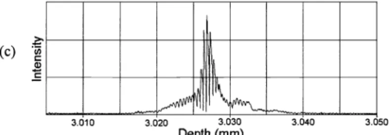
number of used glass slides. Fig. 2(b) shows the result when 4 slides were used. This fringe pattern has a FWHM of about 6 pm. Fig. 2(c) shows the result when 8 slides were used. This fringe pattern has a FWHM of only about 1 .7 rim. However, it
consists of quite significant tails. Note that in using the glass slides in the reference arm, it cannot be sure whether the
dispersion mismatch was enhanced or reduced.
3. RETRIEVAL ALGORITHM
To reduce the effects of the fringe tails on OCT scanning images, we proposed a computer algorithm based on the following
principles: First, an OCT image can be regarded as the superposition of fringe envelopes pixel by pixel with various
intensities, which depend on sample structures. This concept is demonstrated with the equation as
I(i)=I'(j)f(i-j)&
(1)Here, I 'representsthe back-scattered iitnsity andfstands for the normalized interference fringe envelope, which symbolizes
the envelope of the oscillatory distribution in Fig. 2(c). After the convolution shown in (1), I represents the detected signal, which is supposed to originate from depth z.HereN is the assumed pixel number and zlz is the pixel size of the OCT system. We developed a computer algorithm based on an iteration method to retrieve the back-scattered intensity distribution I'(i), which represents the sample structure. We used the detected signal 1(i) multiplied by a factor 2/(M+m) as the initial trial function I'(i), where M and m are the maximum and minimum values of function r(i) defined as
r(i) =
I(j)f(i
—j) I
1(i) (2)
We compared the detected intensity 1(i) to the convolution of the trial function I '(i) and the normalized interference fringe envelope functionf and obtained the difference between them at each pixel d(i). We neglected the difference when it was smaller than 1(i) multiplied by a factor c1, because small computer inaccuracies might be generated during the process and resulted in noise. The proper value of c1 was estimated to be 0.001 .Thedifference d(i) was then multiplied by a factor c2 and added to the original trial function I'(i) to obtain a new function I"(i). The factor c2 was used to adjust the retrieving speed of the program. A larger value of c2 resulted in a higher retrieving speed; however, the process would not approach to a stable solution when the value of c2 was too large. A suitable value of c2 was l/O.055N based on our experience. The new trial function was obtained by replacing the negative values ofl"(i) with 0. Such a process was iterated until the processed image
was satisfactory.
4. RETRIEVED IMAGE RESULTS
In demonstrating the capability ofthe proposed algorithm in real OCT operation, Fig. 3(a) shows the scanning image of
an onion sample when 8 glass slides were inserted into the reference arm for dispersion compensation. Although the
structures of onion cells can be recognized, the effects of fringe tails (spiky features in the figure) did blur the image and reduce the spatial resolution. This image was then processed with the proposed algorithm. After 100 iterations ofthe retrieval procedure, the image quality has been improved, as shown in Fig. 3(b). The spiky features are now tremendously suppressed
and the image contrast is enhanced. Particularly, the layered structures near cell walls can now be clearly seen. It was estimated that the required process time for 100 iterations of a depth scan of 1000 pixels was shorter than 0.25 sec. The
required process time of a frame of 1000 x 200 pixels (1 mm in depth by 1 mm in width) should be shorter than oneminute. With such a process speed, we cannot claim a real-time operation. Although in terms of speed, this process procedure cannot compete with a real-time fast scanning OCT system, which has a frame rate of 8-10 Hz, it is acceptable in certain applications. Development ofsoftware should result in faster process.
4. CONCLUSIONS
In summary, we have demonstrated a novel technique of improving the spatial resolution of an OCT system given a certain light source spectrum, which was not well shaped. By inserting dispersive materials into the reference arm ofthe OCT system,
the resultant dispersion compensation led to a FWHM of the interference fringe envelope smaller than the Fourier
transform-limited value of a Gaussian spectral shape with the same spectral FWHM, at the expense of significant tails. Such tails would blur OCT images if their effects were not removed. In the proposed technique, the tail effects were tremendously
reduced with a retrieval algorithm. OCT real scanning images have shown the promising capability of the proposed
technique.
ACKNOWLEDGEMENTS
This research was supported by National Health Research Institute, The Republic of China, under the grant of
NHRI-GT-EX89.
Proc. SPIE Vol. 4916 252
REFERENCES
1 . C.E. Saxer, J. F. de Boer, B. H. Park, Y. Zhao, Z. Chen, and J. S. Nelson, "High-speed fiber-based polarization-sensitive optical coherence tomography ofin vivo human skin," Opt. Left. 25, 1355-1357 (2000).
2. W. Drexler, U. Morgner, F. X. Kärtner, C. Pitris, S. A. Boppart, X. D. Li, E. P. Ippen, and J. G. Fujimoto, "In vivo
ultrahigh-resolution optical coherence tomogrphy," Opt. Left. 24, 1221-1223 (1999).
3. T. A. Birks, W. J. Wadsworth, and P. St. J. Russel, "Supercontinuum generation in tapered fibers," Opt. Left. 25,
1415-1417 (2000).
4. I. Hartl, X. D. Li, C. Chudoba, R. K. Ghanta, T. H. Ko, J. G. Fujimoto, J. K. Ranka, and R. S. Windeler,
"Ultrahigh-resolution optical coherence tomography using continuum generation in an air-silica microstructure optical fiber," Opt. Left. 26, 608-610 (2001).
5. A. M. Kowalevicz, T. Ko, I. Hartl, J. G. Fujimoto, M. Pollnau, and R. P. Salathé, "Ultrahigh resolution optical coherence tomography using a superluminescent light source" Opt. Express 10, 349-353 (2002).
6. E. A. Swanson, D. Huang, M. R. Hee, J. G. Fujimoto, C. P. Lin, and C. A. Puliafito, "High-speed optical coherence
domain reflectometry, "Opt. Lett. 17, 1 5 1 -153 (1992).
Detector
Fig. 1 Experimental setup ofthe free-space OCT system: BS: beam splitter. L1 and L2: lenses. RM: reflection mirror. BP filter:
Ih\
-L)) (I) a) Nct:YVO4 Ti:sapphire band-pass filter.(a)
a) 3.010 3.620 3.030 3.640 3.050 3.b60 3.b70 3.080 3.090 Depth (mm) 3.000 3.010 3.020 3.030 Depth 3.040 3.050 3.060 3.070 (mm) 3.080Fig. 2(a) and (b) Interference fringe patterns of the OCT system in the cases (a) without dispersion compensation, (b) and (c) with dispersion compensation when 4 and 8 glass slides are used, respectively.
.
(c)
a)
JL
3.010 3.020 3.030 3.040 3.050
Depth (mm)
Fig.2(c) Interference fringe patterns of the OCT system in the cases (a) without dispersion compensation, (b) and (c) with
dispersion compensation when 4 and 8 glass slides are used, respectively.
(a)
(b)
0.1mm
Fig.3 OCT images of onion cells of the cases: (a) before process and (b) after process.
Proc. SPIE Vol. 4916 254