This article was downloaded by: [National Chiao Tung University 國立交通大學] On: 27 April 2014, At: 17:22
Publisher: Taylor & Francis
Informa Ltd Registered in England and Wales Registered Number: 1072954 Registered office: Mortimer House, 37-41 Mortimer Street, London W1T 3JH, UK
Journal of the Chinese Institute of Engineers
Publication details, including instructions for authors and subscription information:
http://www.tandfonline.com/loi/tcie20
Adaptive backstepping motion control of induction
motor drives
Shir‐Kuan Lin a & Chih‐Hsing Fang b a
Department of Electrical and Control Engineering , National Chiao Tung University , Hsinchu, Taiwan, 300, R.O.C.
b
Department of Electrical and Control Engineering , National Chiao Tung University , Hsinchu, Taiwan, 300, R.O.C. Phone: 886–3–5918532; Fax: 886–3–5918532; E-mail: Published online: 04 Mar 2011.
To cite this article: Shir‐Kuan Lin & Chih‐Hsing Fang (2004) Adaptive backstepping motion control of induction motor
drives, Journal of the Chinese Institute of Engineers, 27:3, 449-454, DOI: 10.1080/02533839.2004.9670892 To link to this article: http://dx.doi.org/10.1080/02533839.2004.9670892
PLEASE SCROLL DOWN FOR ARTICLE
Taylor & Francis makes every effort to ensure the accuracy of all the information (the “Content”) contained in the publications on our platform. However, Taylor & Francis, our agents, and our licensors make no
representations or warranties whatsoever as to the accuracy, completeness, or suitability for any purpose of the Content. Any opinions and views expressed in this publication are the opinions and views of the authors, and are not the views of or endorsed by Taylor & Francis. The accuracy of the Content should not be relied upon and should be independently verified with primary sources of information. Taylor and Francis shall not be liable for any losses, actions, claims, proceedings, demands, costs, expenses, damages, and other liabilities whatsoever or howsoever caused arising directly or indirectly in connection with, in relation to or arising out of the use of the Content.
This article may be used for research, teaching, and private study purposes. Any substantial or systematic reproduction, redistribution, reselling, loan, sub-licensing, systematic supply, or distribution in any
form to anyone is expressly forbidden. Terms & Conditions of access and use can be found at http:// www.tandfonline.com/page/terms-and-conditions
Short Paper
ADAPTIVE BACKSTEPPING MOTION CONTROL OF INDUCTION
MOTOR DRIVES
Shir-Kuan Lin and Chih-Hsing Fang*
ABSTRACT
In this paper, an adaptive backstepping controller is proposed for position track-ing of a mechanical system driven by an induction motor. The mechanical system is a single link fixed on the shaft of the induction motor such as a single-link robot. The backstepping methodology provides a simpler design procedure for an adaptive con-trol scheme and provides a method to define the sliding surface if the robust sliding-mode control is applied. Thus, the backstepping control can be easily extended to work as an adaptive sliding-mode controller. The presented position control system is shown to be stable and robust to parameter variations and external disturbances. The effectiveness of the proposed controllers is demonstrated in experiments.
Key Words: adaptive backstepping control, sliding-mode control, induction motor.
*Corresponding author. (Tel: 5918532; Fax: 886-3-5820050; Email: [email protected])
The authors are with the Department of Electrical and Control Engineering, National Chiao Tung University, Hsinchu, Taiwan 300, R.O.C.
I. INTRODUCTION
Featuring simple construction, ruggedness reli-ability, and minimum maintenance, induction motors have been widely used in many industry applications and recently even in the field of robotic applications (Hu et al., 1996). In such applications the mechanical load driven by an induction motor must track a time-varying trajectory that specifies its desired positions (Fusco, 2001). To counteract these variations, analyzing and designing the tracking performance of a position controller for a torque-regulated induction motor is proposed in this paper.
A high performance motor drive must have good position command tracking and load regulating response. In real practice, the induction motor drive is influ-enced by uncertainties, which are usually composed of unpredictable plant parameter variations, external load disturbances, unmodelled and nonlinear dynam-ics of the plant. Nonlinear control approaches have been developed to deal with such problems. The model reference adaptive parameter variation problems (Ko and Jeon, 1996). The other method is adaptive backstepping control (Jankovic, 1997). The latter is
simpler in its control design procedure. To compen-sate for uncertainties, much work has been done to develop sliding-mode control schemes (Xia et al., 2000). In this paper, a new adaptive backstepping posi-tion control scheme is developed. The backstepping control method consists of applying a single-variable control scheme to a multivariable control system. It first handles one variable while assuming the other vari-ables can be assigned arbitrarily. Then, the rest of the state equations, with the other variables, are treated by the same procedure. The main contribution of this pa-per is to develop an adaptive sliding-mode backstepping position controller for a mechanical system driven by an induction motor. This paper emphasizes the mo-tion control of a mechanical system, for a high perfor-mance torque control induction motor. For full infor-mation about the torque control scheme, the reader is refered to (Lin and Fang, 2001). Our proposed motion control scheme combines adaptive backstepping and sliding-mode technology, so that it can adaptively tune the control gains with respect to changes in the system parameters and can also compensate for uncertainties. The resulting control law provides a method to assign the sliding surfaces for designing sliding-mode control. This special feature of the backstepping control meth-odology is demonstrated in this paper. The robustness of the proposed control scheme will be verified by an experiment with a sinusoidal disturbance.
450 Journal of the Chinese Institute of Engineers, Vol. 27, No. 3 (2004)
II. REVISITING A TORQUE CONTROL LAW
This section briefly reviews the sliding-mode torque control scheme, which is adopted as the inner loop of the overall control system. The details of this torque control scheme are presented in (Lin and Fang, 2001). The mathematical model of a three-phase, Y-connected induction motor in a stator-fixed frame (αs,
βs) can be described by five nonlinear differential equa-tions with four electrical variables [stator currents (iαs,
iβs) and rotor fluxes (ϕαr, ϕβr)], a mechanical vari-able [rotor speed (ωm)], and two control variables [stator voltages (uαs, uβs)] ( Novotny and Lipo, 1996) as follows:
iαs= –γiαs+ Kτrϕαr+ pKωmϕβr+αuαs (1) iβs= –γiβs+ Kτ rϕβr– pKωmϕαr+αuβs (2) ϕαr= Mτriαs– 1τrϕαr– pωmϕβr (3) ϕβr= Mτriβs– 1τ rϕβr+ pωmϕαr (4) ωm= – B Jωm+ Te J – TL J (5)
where Rs and Rr are the stator and rotor resistance,
Ls, Lr, and M are respectively the stator, rotor, and mutual inductance, B and J are the friction coeffi-cient and the moment of inertia of the motor, Te and are TL the electromagnetic torque and external load torque, τr=Lr/Rr is the rotor time constant, and the parameters are defined as σ=1−M2
/(LsLr), K=M/(σLsLr),
γ=Rs/(σLs)+RrM2/(σLsLr 2
), and α=1/(σLs). Note that
Te=kT(iβsϕαr−iαsϕβr) (6) where kT=(3P/4)(M/Lr), P is the number of pole-pairs. The torque control scheme is to construct a volt-age controller u=[uαs uβs]T to ensure that the electro-magnetic torque Te follows the desired torque trajec-tory Teref. The sliding-mode torque control scheme (Lin and Fang, 2001) proposes to use
u = – D– 1 b + kcs +
µc1Sat(s1)
µc2Sat(s2) (7) where s=[s1, s2]T are the sliding surfaces of torque and flux, D, b, kc, and (µc1, µc2) are the nonlinear control factors that are defined in detail in (Lin and Fang, 2001). Note that the saturation function Sat(si) is defined as
Sat(si) =
si
si +λ
(8) where λ is a smooth factor.
Furthermore, the flux observer (Lin and Fang, 2001) is iαs= –γiαs+ Kτrϕαr+ pKωmϕβr+αuαs+Λ1 (9) iβs= –γiβs+ Kτ rϕβr+ pKωmϕαr+αuβs+Λ2 (10) ϕαr= Mτriαs– 1τrϕαr– pωmϕβr+Λ3 (11) ϕβr= Mτ riβs– 1τrϕβr+ pωmϕαr+Λ4 (12) where iαs, iβs, ϕαr, ϕβr are the estimators of iαs, iβs,
ϕαr, ϕβr, respectively. Let the estimate errors be e= [e1, e2, e3, e4]T=[iαs−iαs, iβs−iβs, ϕαr−ϕαr, ϕβr−ϕβr]T. The estimate inputs are
Λ1= –ρ1sign(e1) –ζ1 Λ2= –ρ2sign(e2) –ζ2 (13) Λ3 Λ4 = pkωφ – pωm m kφ K τr pKωm – pKωm τK r – 1 ⋅ Λ1 Λ2 – ρρ3Sat(e3) 3Sat(e4) (14) where the adaptive laws are
ρρ=ρρ= ρ1 ρ2 = e1 e2 (15) ζζ=ζ= ζ1 ζ2 = ee1 1 (16)
and, kφ is a constant and [ρ3, ρ4] are the upper bounds of the uncertainty of estimate flux equations.
Then, the estimated torque (Te) and estimated flux (φφ) are calculated as follows,
Te= kT(iβsϕαr– iαsϕβr) (17) φφ= ϕαr 2 +ϕβr 2 (18) and the result of estimated signals are used as the slid-ing-mode toque controller of feedback signals.
III. ADAPTIVE BACKSTEPPING MOTION CONTROL
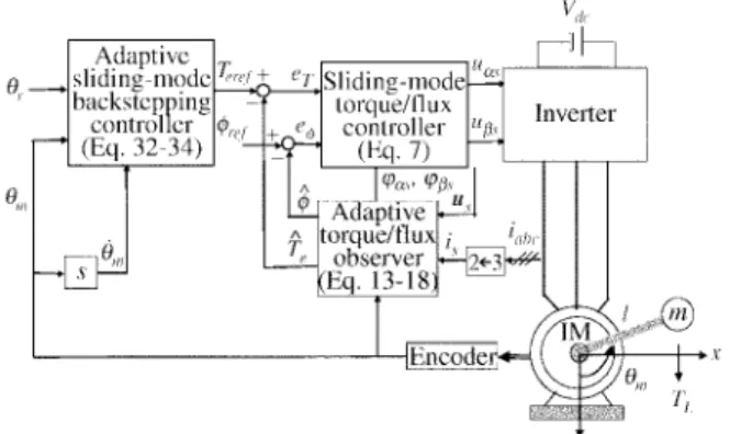
This paper tried to develop a new backstepping control law for motion tracking of an induction motor. The sliding-mode torque control scheme (Lin and Fang, 2001) is implemented as an inner loop of torque control. Fig. 1 shows the control structure with a rod fixed on the shaft axis of the motor which is an example of a single link robot. The following con-text is then concentrated on the motion tracking of a
mechanical system driven by an induction motor. The dynamics of the mechanical system are
Jθm= – Bθm– mgl sin(θm+θ0) + kTuT
= – Bθm– mgl cosθ0sinθm
– mgl sinθ0cosθm+ kTuT (19) where θm is the angular displacement of the shaft, m is the mass of the rod, l is the distance from the shaft center to the center of mass of the rod, g is the gravita-tional acceleration, and θ0 is the null angle from the line of gravity. Furthermore, (19) is simplified as
θm= – BJθm– (Lbsinθm+ Lccosθm) + KJuT (20) where BJ=B/J, Lb=mgl cosθ0/J, Lc=mgl sinθ0/J, KJ=
kT/J. Note that J>0.
The control objective is to design a controller uT that forces the position variable θm to track a desired trajectory denoted by θm* , which is second-order con-tinuously differentiable. Define the tracking error as
ep=θm *−θ
m. The system in (20) can be rewritten as es= ep=θm * –θm es= ep=θm * + BJθm+ (Lbsinθm+ Lccosθm) – KJuT (21) The concept of the backstepping is first to consider only one of the states. We consider ep and let the Lyapunov-like function be V0=e2p/2. The derivative of V0 along the trajectory of ep is
V0= epep= – c1e2p+ ep(es+ c1ep) (22) The purpose of the special form of (22) is to achieve
V0=−c1e2p<0 for ep≠0 if es were kept to be −c1ep. However,
es cannot be arbitrarily assigned. The backstepping design is then to consider the error z≡es−(−c1ep). es is actually the integrator of ep. If −c1ep were inserted into the system as a feedback term, then the system would be stable. However, this can be treated by add-ing (−c1ep) in the position of es in the actual system and “backstepping” −(−c1ep) through the integrator.
According to (21), the dynamics of z are
z = KJ(h T x – uT) (23) where h = 1/KJ BJ/KJ Lb/KJ Lc/KJ , x = θm * + c1(θm * –θm) θm sinθm cosθm (24)
Note that the parameters of h are assumed unknown. We need to design an adaptive backstepping control-ler to estimate these parameters on line. The esti-mates of the unknown parameters are denoted by h and the estimation error is h=h− h.
Now, consider a new Lyapunov-like function:
V1= 12(e2p+ z2+ KJh TΓΓ
h) (25)
where ΓΓΓΓΓ is a positive definite matrix. The derivative of V1 along the trajectory of the system, i.e., (21), is
V1= – c1ep2+ epz + zKJ(h T x – uT) + KJh TΓΓ h = –εTFεε (26) where εε= ez , F =p c1 – 1/2 – 1/2 c2 (27) if the controller and the adaptive laws are, respectively,
uT= h T x (28) h = – zΓΓ– 1x (29) where xT
=xT +[c2z, 0, 0, 0]. It is easy to show that the symmetrical matrix F is positive definite and then
V1≤0 if c1c2>1/4.
Proposition 1. Consider the system in (20). The
an-gular displacement θm of the system will asymptoti-cally converge to the desired trajectory θm* if the con-troller and the adaptive law are, respectively, (28) and (29) with c1c2>1/4.
Proof. V1 in (25) is a Lyapunov-like function, so we
cannot directly apply the Lyapunov stability theory. However, V1 is bounded below and non-increas-ing, which implies that lim
t→ ∞V1(t)=V1∞ exists (Ioannou and Sun, 1996). Thus, ep,z, h∈L∞, so that h∈L∞ since
h is constant. It then follows from (21) and (23) that
Fig. 1 Overall system of the position control of an induction motor
452 Journal of the Chinese Institute of Engineers, Vol. 27, No. 3 (2004) ep, z∈L∞. Integrating (26), we obtain V1(t)|t=0−V1∞ ≥ εεT Γε Γε 0 ∞
, and then εε∈L2. A corollary of Barbalat’s lemma (Ioannou and Sun, 1996) states that εε∈L∞ and
εε∈L2 imply εε→0 as t→∞. This completes the proof. It should be remarked that uT in (28) is used as the reference active torque Teref for the inner loop torque control (see Fig. 1).
IV. ROBUSTNESS
The above mechanical model is an ideal case. We now consider a more practical case by introduc-ing an uncertainty in (20) to obtain
θm=−BJθm−(Lbsinθm+Lccosθm)+KJuT+∆ (30)
where ∆≡KJ∆1 is a bounded uncertainty satisfying
|∆1|≤κ, in which κ>0 is an unknown bound. After introducing the uncertainty, (23) should also be modi-fied as
z = KJ(hTxθ–∆1– uT) (31)
Let the sliding surface be s=εε and define the Lyapunov function as V=(1/2)sT
s. It can be shown
that a sliding-mode controller uT=hTx+κsign(z) can draw the overall system to the sliding surface s=0 and then θm asymptotically approaches the target θm
* , if all system parameters are known. However, we as-sume that the parameters are unknown. Thus, we require the following adaptive sliding-mode back-stepping controller.
Proposition 2. Consider the system (30). The
angu-lar displacement θm of the system will asymptotically converge to the desired trajectory θm* if the control-ler and the adaptive law are, respectively,
uT= hTx +κsign(z) (32) h = zΓΓ– 1x (33) κ=γρ– 1 z (34)
with c1c2>1/4 for x and γρ>0.
Proof. Let the Lyapunov-like function V2 be
V2= 12(εεTεε+ KJh TΓΓ h + KJγρκ 2 ) (35)
where κ=κ−κ. Applying (32), we obtain the deriva-tive of V2 along the trajectory of the system (30) as
V2= –εεTFεε– zKJ(∆1+κsign(z)) + KJγρκκ ≤–εεTFεε+ K J(κ z –κ z ) + KJγρκκ = –εεTFεε ≤0 (36)
Note that −∆1≤|∆1z|≤κ|z|. Then V2 is bounded below and non-increasing. The rest of the proof is similar to the last part of the proof of Proposition 1 and is thus omitted.
V. EXPERIMENTS
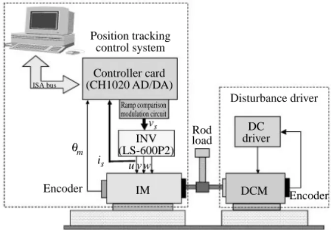
The experimental system for the proposed adap-tive sliding-mode backstepping position control is shown in Fig. 2. This is a PC-based control system and the ramp comparison modulation circuit is to drive the voltage source inverter. The induction mo-tor in the experimental system is a 4-pole, 5HP, 220V motor with the rated current, speed, and torque of 13.4A, 1730rpm, and 18Nm, respectively. The en-coder has 4096 counters per revolution. The param-eters of the motor are Rs=0.3Ω, Rr=0.36Ω, Ls=Lr=48 mH, and M=45 mH. Those of the mechanical system are J≈0.0069 kgm2
, l≈0.45 m, and m≈3 kg.
Two experiments are conducted: 1) reference trajectory generated by set-point positions, and 2) robust position control.
In the first experiment, the motor is asked to go to θm=π/2 at t=0.5 s, then to θm=π at t=5 s, and finally to return to θm=π/2 again at t=8 s. However, the de-sired trajectory is generated by the reference model of
θm * = – ktθm * – ksθm * + ksθr (37)
where θr is the angular displacement command, and kt, and ks are positive constants, which can be selected such that s2
+kts+ks=(s+p1)(s+p2) with p1, p2>0. The gains of the reference model are kt=10 and ks=30. It should be remarked that the reference torque TTref in the inner loop is generated by the adaptive sliding-mode backstepping controller stated in Proposition 2, while the reference flux φref is given as a constant of 0.43 Wb. The experi-mental results are shown in Fig. 3. It can be seen that the steady-state error is negligible, and the transient re-sponse also meets the reference model standard. The history of the estimated torque shows that the values are
Position tracking control system Disturbance driver DC driver DCM IM Encoder Encoder Rod load INV (LS-600P2) Ramp comparison modulation circuit Controller card (CH1020 AD/DA) ISA bus m θ is vs u v w
Fig. 2 Experimental system
3.5 3 2.5 2 1.5 1 0.5 0 0 2 4 6 Time (sec) (a) 8 10 12
Position (rad) : Reference angle
: Actual angle Torque command Estimated torque 30 25 20 15 10 5 0 -5 0 2 4 6 Time (sec) (b) 8 10 12 T orque (Nm) 0.06 0.04 0.02 0 -0.02 -0.04 -0.06 0 2 4 6 Time (sec) (c) 8 10 12 Position (rad) : Tracking error 0.5 0.45 0.4 0.35 0.3 0.25 0.2 0.15 0.1 0.05 0 2 4 6 Time (sec) (d) 8 10 12 Flux (web) : Reference angle : Estimated flux
Fig. 3 Responses of a set point positions command: (a) position; (b) torque command and estimated torque; (c) tracking error (θm
*−θ
m);
(d) rotor flux
around zero for θm=π and around 14Nm for θm=π/2, which is consistent with the physical property.
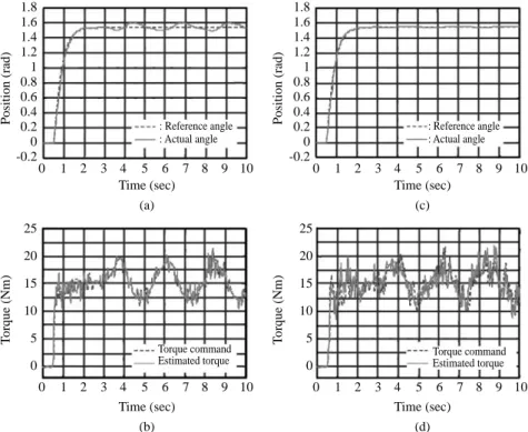
The second experiment asks the motor to go to
θm=π/2 at t=0.5 s. The desired trajectory is also gener-ated by (37). However, there is disturbance torque TL= 3.5sin2(t−3) Nm, ∀t≥3, beginning at t=3 s, which is generated by an external DC-motor. The experimen-tal results for the control laws in Propositions 1 and 2 are shown in Fig. 4. It can be seen that the adaptive sliding-mode backstepping controller can compensate for the sinusoidal disturbance, whereas the control law in Proposition 1 cannot. This verifies the robustness of the proposed control law in Proposition 2.
VI. CONCLUSIONS
This paper presents a new adaptive backstepping motion control for a mechanical system driven by an in-duction motor. We adopt the sliding-mode torque control proposed in Lin and Fang (2001) as the inner loop controller, which ensures that the electromagnetic torque of the motor will closely follow the torque command. The main point of this paper is then to design a position con-troller, which generates the torque command to the inner loop controller so that asymptotic stability can be ensured. This position controller is derived from backstepping methodology. On the other hand, the backstepping method provides a way to define the sliding surface for the sliding-mode control. That is to define the sliding surface func-tions as state variables of the backstepping control system,
such as εε in Eq. (27). We use this concept to deal with a
system containing an uncertainty. The proposed control scheme is the so-called adaptive sliding-mode backstepping controller stated in Proposition 2. The trol system is implemented on a PC-based system to con-trol an induction motor with a rod fixed on the shaft. Both set-point and tracking position control experiments verify the control theory and show that the proposed control scheme is useful for industrial applications.
ACKNOWLEDGMENTS
This paper was, in part, supported by the Na-tional Science Council, Taiwan under Grant No. NSC90-2212-E-009-063.
NOMENCLATURE
^ estimated quantities
* commanded or reference quantities ~ error quantities
B friction coefficient
c1, c2 control gains
e estimate errors
ep, es displacement and speed tracking errors
g gravitational acceleration
h adaptive backstepping parameters
iαs, iβs stator currents in the stationary frame
J the moment of inertia of the motor
kT torque gain
454 Journal of the Chinese Institute of Engineers, Vol. 27, No. 3 (2004)
kt, ks gains of reference model
l shaft length
Ls, Lr, M stator, rotor, and mutual inductance
m mass of the rod
p1, p2 poles of reference model
Rs, Rr stator and rotor resistance
s laplace expression symbol
s sliding surfaces
Te, TL electromagnetic torque and external load
u voltage controller
uαs, uβs stator voltages in the stationary frame
x adaptive backstepping input signal
z backstepping error
∆, ∆1 uncertainty bounded
θm angular displacement of the shaft
θ0 null angle
Λ1,..., Λ4 estimate inputs
τr rotor time constant
ϕαr, ϕβr rotor fluxes in the stationary frame
ωm rotor speed
REFERENCES
Fusco, G., 2001, “Tracking Performance of an H∞ Po-sition Controller for Current-Fed Induction Mo-tors under Mechanical Load Variations,”
Pro-ceedings of the IEEE/ASME International Con-ference on Advanced Intelligent Mechatronics,
Como, Italy, Vol. 2, pp. 713-718.
Hu, J., Dawson, D. M., and Qian, Z., 1996, “Position
Tracking Control for Robot Manipulators Driven by Induction Motors without Flux Measure-ments,” IEEE Transactions on Robotics and
Auto-mation, Vol. 12, No. 3, pp. 419-438.
Ioannou, P. A., and Sun, J., 1996, Robust Adaptive
Con-trol, Prentice-Hall, Upper Saddle River, NJ, USA.
Jankovic, M., 1997, “Adaptive Nonlinear Output Feedback Tracking with a Partial High-Gain Ob-server and Backstepping,” IEEE Transactions on
Automatic Control, Vol. 42, No. 1, pp. 106-113.
Ko, J. S., and Jeon, C. H., 1996, “New MRAC Load Torque Observer for the Position Control of BLDC Motor,”
Proceedings of the IEEE International Conference on Industrial Technology, (ICIT ’96), Shanghai, China,
pp. 565 -569.
Lin, S. K., and Fang, C. H., 2001, “Sliding-Mode Direct Torque Control of an Induction Motor,” The 27th
Annual Conference of the IEEE Industrial Electron-ics Society, (IECON’01), Vol. 3, pp. 2171-2177.
Novotny, D. W., and Lipo, T. A., 1996, Vector
Con-trol and Dynamics of AC Drives, Oxford Press,
New York, USA.
Xia, Y., Yu, X., and Oghanna, W., 2000, “Adaptive Robust Fast Control for Induction Motors,” IEEE
Transactions on Industrial Electronics, Vol. 47,
No. 4, pp. 854 -862.
Manuscript Received: Feb. 17, 2003 Revision Received: Jun. 17, 2003 and Accepted: Aug. 29, 2003
Fig. 4 Responses of a set point position command: in the adaptive backstepping controller: (a) position; (b) torque command and esti-mated torque; in the adaptive sliding-mode backstepping controller: (c) position; (d) torque command and estiesti-mated torque
1.8 1.6 1.4 1.2 1 0.8 0.6 0.4 0.2 0 -0.2 0 1 2 3 4 5 Time (sec) (a) 6 7 8 9 10 0 1 2 3 4 5 6 7 8 9 10 0 1 2 3 4 5 6 7 8 9 10 0 1 2 3 4 5 6 7 8 9 10
Position (rad) : Reference angle
: Actual angle : Reference angle : Actual angle Torque command Estimated torque 25 20 15 10 5 0 Time (sec) (b) T orque (Nm) 1.8 1.6 1.4 1.2 1 0.8 0.6 0.4 0.2 0 -0.2 Time (sec) (c) Position (rad) 25 20 15 10 5 0 Time (sec) (d) T orque (Nm) Torque command Estimated torque