IEEE PHOTONICS TECHNOLOGY LETTERS, VOL. 16, NO. 7, JULY 2004 1637
120-nm Bandwidth Erbium-Doped Fiber Amplifier
in Parallel Configuration
Chien-Hung Yeh, Chien-Chung Lee, and Sien Chi
Abstract—A new - to -band erbium-doped fiber amplifier (EDFA) module, which reaches 120-nm gain bandwidth of 1480 to 1600 nm, has been experimentally investigated and demonstrated by using coupled structure. A 32.8-, 34.7-, and 38.1-dB peak gain is obtained at 1504, 1532, and 1568 nm, respectively, when the input signal power is 30 dBm. In addition, this proposed amplifier also provides a broad-band amplified spontaneous emission (ASE) light source of 1480–1606 nm with the output level above 40 dBm.
Index Terms—Coupled structure, erbium-doped fiber amplifier
(EDFA), -band, wavelength-division-multiplexing (WDM) systems, wide-band.
I. INTRODUCTION
W
IDE-BAND erbium-doped fiber amplifiers (EDFAs) are considerably interesting for high-capacity transmission in dense wavelength-division-multiplexing (DWDM) systems. However, the transmission capacities in DWDM systems were limited by the gain bandwidth of the -band EDFAs (1530–1560 nm). Furthermore, the -band (1560–1610 nm) fiber amplifier techniques have been achieved, such as the EDFAs by using a longer erbium-doped fiber (EDF) than -band EDFAs [1], the fiber Raman amplifiers [2], and the different hybrid amplifiers [3]. In addition, a wide-band EDFA from - to -band by employing coupled structure has also been studied [4]. Recently, a new -band (1450–1530 nm) amplification technique, which utilizes erbium-doped silica fiber with depressed cladding design and 980-nm pump laser to generate EDF gain extension effects, has been reported [5]. Therefore, by using this new -band amplifier module with coupled structure can retrieve the wide gain bandwidth from 1480 to 1600 nm. In this letter, we propose and experimentally demonstrate an - to -band EDFA module with 120-nm gain bandwidth (1480 to 1600 nm). In addition, it also can observe 126 nm (1480–1606 nm) amplified spontaneous emission (ASE) light source.II. EXPERIMENTS ANDDISSCUSSIONS
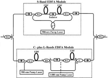
Fig. 1 shows the experimental setup for the proposed EDFA module with coupled structure. This proposed configuration is constructed by two 1480/1550-nm WDM couplers , an -band EDFA module composed of two EDFA stages and a power-sharing 980-nm pump laser, and a - to -band EDFA module with two EDFA stages. From Fig. 1, two WDM couples were used to connect two individual EDFA modules in parallel,
Manuscript received December 18, 2003; revised February 26, 2004. The authors are with the Institute of Electro-Optical Engineering, Na-tional Chiao Tung University, Hsinchu 30050, Taiwan R.O.C. (e-mail: [email protected]).
Digital Object Identifier 10.1109/LPT.2004.828357
Fig. 1. Experimental setup for the proposed wide-band EDFA module.
and the output wavelengths of the Port “1,” “2,” and “3” were 1480–1600, 1480–1520, and 1520–1600 nm, respectively. The -band EDF inside EDFA module has a depressed cladding de-sign in order to provide a sharp, high attenuation, long wave-length cutoff filter in the EDF. The cutoff wavewave-length is near at 1530 nm. The fabrication uses standard modified chemical vapour deposition processes and solution doping for incorpo-ration of aluminum and erbium. The core and cladding diam-eters are 4 and 22 m, respectively. The numerical aperture of the core, relative to the depressed cladding, is 0.22. The back-ground loss is less than 5 dB/km. This -band EDFA was fu-sion direct spliced to SMF-28 using standard setting. Typical splice losses were 0.5 dB. However, the composition of the core is approximately 2.5% GeO , 5.5% Al O , and 92% SiO , with 0.15 wt% Erbium. The depressed cladding is approximately 3% Fluorine, 0.5% P O , and 96.5% SiO . The fiber in the first stage has the fiber length of 20 m, and can provide low noise figure and medium gain by forward pumping. The fiber in the second stage has the fiber length of 30 m and can produce large output power by backward pumping. In addition, the optical iso-lator between these two stages can reduce backward ASE and improve noise figure performance. The total pump power of this amplifier module can be up to 280 mW while the bias current is operated at 356 mA. Furthermore, the evolution from a standard EDFA to this -band design by the introduction of a continuous long wavelength cutoff filter in the EDF. Although the spectrum indicates strong gain at -band wavelengths, the gain cannot be realized because of strong ASE at the 1530-nm peak. Intro-duction of a progressively sharper long wavelength cutoff filter suppresses the gain in the - and -bands, so that the -band region can exhibit increasing gain, as ASE from the 1530-nm
1638 IEEE PHOTONICS TECHNOLOGY LETTERS, VOL. 16, NO. 7, JULY 2004
Fig. 2. Gain and noise figure spectra of theS-band EDFA while the input powers are 0,015, and 030 dBm, respectively. The insert is ASE spectrum of theS-band amplifier module.
peak does not grow and limit the population inversion. The final result is a complete suppression of the longer wavelength gain, resulting in a usable high net gain in the -band.
The - plus -band amplifier module is constructed by two EDFA stages, a 1 2 and 50 : 50 optical coupler ( ), and a / (1564/1570 nm) band splitter (BS) with insertion loss of 0.43 dB, as shown in Fig. 1. The output ranges of the BS for Port “a,” “b,” and “c” was 1500–1610, 1570–1610, and 1500–1564 nm, respectively. The first stage has a 12-m-long EDF and a 980-nm pump laser of 65 mW. The second stage has an 88-m-long EDF and a 1480-nm pump laser of 95 mW. Besides, the first stage EDFA with forward pumping can provide the low noise figure and medium gain.
To investigate the performances of the proposed amplifier, the input signal powers Pin and dBm are used to probe the amplifier gain and noise figure spectra, respectively. Fig. 2 shows the gain and noise figure spectra of the -band EDFA module in Fig. 1 over the wavelengths of 1480 to 1520 nm. The insert of Fig. 2 shows the ASE spectrum of the -band amplifier with 40-nm bandwidth (1480–1520 nm). Therefore, the gain and noise figure of the -band amplifier can achieve 34.1 and 5.0 dB at 1506 nm when the input power is 30 dBm. The gain of 10 dB is observed in Fig. 2 when the input power of 15 dBm over the wavelengths of 1480 to 1520 nm.
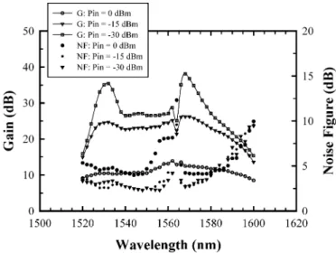
Fig. 3 shows the gain and noise figure spectra for the - to -band EDFA module in Fig. 1 over the wavelength ranges from 1520 to 1600 nm. The amplifier module can reach 80-nm gain bandwidth between 1520 to 1600 nm, and the peak gains of 35.4 and 38.1 dB (noise figure of 3.3 and 2.7 dB) are retrieved at 1532 and 1568 nm when the input power is 30 dBm. Because of the band gap (1564–1570 nm) loss of the / BS and the insertion loss of coupler, the gain and noise figure spectra will drop and degrade at near 1564 nm, as shown in Fig. 3. Due to the insertion loss ( 3 dB) of a 1 2 and 50 : 50 coupler, it would loss some gain in this proposed amplifier. However, the - to -band gain can be increased about 2.5 dB easily if / coupler is used instead of 50 : 50 coupler in Fig. 1.
Fig. 4(a) and (b) indicates the gain and noise figure spectra for the proposed configuration in Fig. 1 while the input signal
Fig. 3. Gain and noise figure spectra of theC- to L-band EDFA module in Fig. 1 when the input power Pin= 0; 015; and 0 30 dBm, respectively.
Fig. 4. (a) Gain and (b) noise figure spectra of the proposed configuration in Fig. 1 while the input power Pin = 0; 015; and 0 30 dBm, respectively. The insert of (a) and (b) are the ASE spectrum of the proposed EDFA and the insertion loss of two 1480/1550-nm WDM couplers versus the wavelengths, respectively.
YEH et al.: 120-nm BANDWIDTH EDFA IN PARALLEL CONFIGURATION 1639
power Pin and dBm, respectively. The in-sert of Fig. 4(a) shows the ASE spectrum with 120-nm band-width of 1480 to 1600 nm for this proposed wide-band struc-ture. In addition, the insert of Fig. 4(b) presents that the inser-tion loss spectra of Port “2” and “3” for two 1480/1550-nm WDM couplers, and two loss curves cross around 1522 nm. Fig. 4(a) represents the gain spectra over 120-nm bandwidth of 1480 to 1600 nm. It also shows the peak gain of 32.8, 34.7, and 38.1 dB at 1504, 1532, and 1568 nm with 30-dBm input power, respectively. Due to the insertion losses of two WDM couplers [as seen in the insert of Fig. 4(b)], the different gain spectra of this proposed amplifier is smaller than that of the - and - plus -band amplifier individually. The gain spectra could drop at near 1522 and 1564 nm because of the band gap loss of two 1480/1550-nm WDM couplers and the / BS. The noise figure also degraded over the bandwidth from 1480 to 1600 nm in this proposed configuration. Furthermore, this proposed amplifier module based on two new EDFA modules and a coupled structure could achieve 120-nm gain bandwidth of 1480 to 1600 nm. The proposed EDFA can be used to act as the in-line preamplifier or postamplifier when the amplifier in the real transmission systems. According to Fig. 4, the gain and noise figure spectra also show the behavior and perfor-mance of that when the different input signal power levels are applied. Besides, this amplifier also provides a broad-band ASE light source of 1480 to 1606 nm when the output level above 40 dBm. Compared with the past broad-band amplifier tech-niques [6], [7], which used thulium-doped fiber type or Raman amplification, our proposed amplifier employs two EDFA mod-ules in parallel configuration over the gain bandwidth from 1480 to 1600 nm. The proposed EDFA has the advantage of wide bandwidth, potentially lower cost, and simple architecture. As a result, this proposed broad-band amplifier is useful to the future applications in DWDM networks.
III. CONCLUSION
We have experimentally investigated and demonstrated a new - to -band EDFA module with coupled structure, which
reaches 120-nm gain bandwidth of 1480 to 1600 nm. A 32.8-, 34.7-, and 38.1-dB peak gain (7.2-, 4.1-, and 3.2-dB noise figure) is obtained at 1504, 1532, and 1568 nm with 30-dBm input signal power, respectively. In addition, this proposed amplifier also provides a broad-band ASE light source of 1480 to 1606 nm. Therefore, this proposed wide-band EDFA module could be benefited to the future applications in DWDM systems.
ACKNOWLEDGMENT
The authors would like to thank C.-Y. Chen for help with the experiments.
REFERENCES
[1] Y. Sun, J. W. Sulhoff, A. K. Srivasta, J. L. Zyskind, T. A. Strasser, J. R. Pedrazzani, C. Wolf, J. Zhou, J. B. Judkins, R. P. Espindola, and A. M. Vengsarkar, “80 nm ultra-wideband erbium-doped silica fiber ampli-fier,” Electron. Lett., vol. 33, no. 23, pp. 1965–1967, 1997.
[2] S. Namiki and Y. Emori, “Ultrabroad-band Raman amplifiers pumped and gain-equalized by wavelength-division-multiplexed high-power laser diodes,” IEEE J. Select. Topics Quantum Electron., vol. 7, pp. 3–16, Jan./Feb. 2001.
[3] H. Masuda and S. Kawai, “Wide-band and gain-flattened hybrid fiber amplifier consisting of an EDFA and a multiwavelength pumped and Raman amplifier,” IEEE Photon. Technol. Lett., vol. 11, pp. 647–649, June 1999.
[4] B. Min, H. Yoon, W. J. Lee, and N. Park, “Coupled structure for wide-band EDFA with gain and noise figure improvement fromC toL-band ASE injection,” IEEE Photon. Technol. Lett., vol. 12, pp. 480–482, May 2000.
[5] C. H. Yeh, C. C. Lee, and S. Chi, “A tunable S-band erbium-doped fiber ring laser,” IEEE Photon. Technol. Lett., vol. 15, pp. 1053–1054, Aug. 2003.
[6] K. Fukuchi et al., “10.92-Tb/s (2732 40-Gb/s) triple-band/ultra-dense WDM optical-repeatered transmission experiment,” in Communication
Conf. OFC (2001), 2001, Paper PD24-1–PD24-3.
[7] N. E. Jolley et al., “Demonstration of low PMD and negligible multi-path interference in an ultra flat broad EDFA using a highly doped erbium fiber,” in Conf. Optical Amplifiers and Their Amplications’98, 1998, Paper TuD2, pp. 124–127.