國立交通大學
環境工程研究所
博士論文
建立同時部分硝化、厭氧氨氧化及脫硝系統
Development of Simultaneous Partial Nitrification,
Anammox and Denitrification (SNAD) process
研究生:王至誠
指導教授:林志高 教授
建立同時部分硝化、厭氧氨氧化及脫硝系統
Development of Simultaneous Partial Nitrification, Anammox and
Denitrification (SNAD) process
研 究 生:王至誠 Student: Chih-Cheng Wang
指導教授:林志高 Advisor: Jih-Gaw Lin
國立交通大學
環境工程研究所
博士論文
A DissertationSubmitted to the Institute of Environmental Engineering
College of Engineering
National Chiao Tung University
in partial Fulfillment of the Requirements
for the Degree of
Doctor of Philosophy
in
Environmental Engineering
January, 2011
Hsinchu, Taiwan, Republic of China
i
中文摘要
以生物方法去除水中氨氮,傳統上都以硝化脫硝兩個步驟來進行。在硝化時需要大量的曝 氣動力提供氧氣作為電子接受者,使氨氮轉換為硝酸鹽而進行脫硝步驟。脫硝需要加入大 量的有機物作為電子提供者,此方法不僅使得操作費用提升,更有可能導致處理效率低落 時,有機物隨著放流水排出,成為另一種污染源。再者,在脫硝不完全時將會產生一氧化 二氮此種溫室氣體,而加劇溫室效應。本研究將建立一種新穎脫硝方法,“同時部分硝化、 厭氧氨氧化及脫硝技術”,將約莫二分之一的氨氮硝化成亞硝酸鹽後,利用氨氮作為電子提 供者,亞硝酸鹽為電子接受者,直接進行脫硝,不需要添加任何有機物,也可節省一半以 上的曝氣費用。再者,若污水中含有少量之有機物,亦可進行脫硝,去除有機物。同時部 分硝化、厭氧氨氧化及脫硝技術比較傳統方法可節省 60%以上的費用。 本文中將找尋適當污泥,並針對所取得之污泥進行 16S-rRNA 分析,比對基因庫中相關文 獻的菌種相似度,以確認取得污泥中有所需要之厭氧氨氧化菌。同時進行質能平衡之計算, 探討氮在本系統中的流佈。在實驗室中建立一組穩定操作之反應槽,以垃圾掩埋場滲出水 作為進流,探討在不同的氮負荷及有機負荷條件下部分硝化、厭氧氨氧化及脫硝程序之氨 氮去除效能。結果發現,氮負荷率的提升會影響處理效率,經處理後亞硝酸鹽氮濃度幾乎 趨近於零,而硝酸鹽氮濃度則不超過 36 mg/L,氨氮去除效率最高可達 94%。經模式計算 後,滲出水總氮的去除在此程序中有 69-88%是藉由部分硝化及厭氧氨氮氧化所完成,而化 學需氧量去除率則只有 21-45%。最後分析污泥中菌相的分佈,利用 qPCR 進行分析,包括 好氧氨氧化菌,好氧亞硝酸鹽氧化菌,厭氧氨氧化菌以及與總菌數之間的比例。本研究成 功地利用同時部分硝化、厭氧氨氧化及脫硝程序去除污水中含有氮及有機污染物,並證實 所馴養的微生物包含厭氧氨氧化菌。ii
Abstract
The Simultaneous partial nitrification, anaerobic ammonium oxidation (Anammox) and
denitrification (SNAD) process is an innovative biotechnology for the replacement of the
traditional nitrification followed by denitrification. The advantage of the SNAD process include
less than 60% of operation cost from aeration over the traditional nitrification followed by
denitrification, because only half of ammonium stream is required to converting intonitrite and
consequently couples the other half of ammonium stream to nitrogen gas. Moreover, the other
merit of the SNAD process could remove organic matter by denitrification in the same reactor,
which is not able to accomplish by the other autotrophic denitrification processes. The SNAD
process was successfully operated in a continuous stirred tank reactor (CSTR) landfill-leachate
treatment plant and in a lab-scale sequence batch reactor (SBR). To reveal the SNAD microbial
community in the landfill-leachate treatment plant, the 16S rRNA of the sludge from it was
analyzed by the molecular tools, which are DNA extraction and Polymerase Chain Reaction
(PCR). The result of the 16S rRNA analysis identified that Anammox bacteria were dominant in
the SNAD process. On the other hand, we confirm that the Anammox activity contribute most of
nitrogen removal by a nitrogen mass balance approach . The result from it indicated the total
nitrogen (TN) removal from the combined partial nitrification and Anammox route accounted for
75.5%, while the heterotrophic denitrification contributed to TN removal of 7.7% and COD
removal of 23.2%.
For the lab-scale study, the lab-scale SBR SNAD process was initially inoculated the biomass
from the full-scale landfill-leachate treatment plant. After adaptation of the biomass, four stages
(I to IV) with varying nitrogen loading rate (NLR)was examined for the process performance.
iii
concentration was close to zero and the nitrate concentration was less than 36 mg/L in all the
stages during the operation period. The total nitrogen removal in the SBR resulted mainly from
partial nitrification and Anammox (69-88%) that was evaluated by a stoichiometric model.
Overall, the SNAD process offers validated performance on simultaneous nitrogen and chemical
iv
誌 謝
本 論 文 承 蒙 指 導 教 授 林 志 高 博 士 , 悉 心 指 導 與 鼓 勵 , 得 以 順 利 完 成 , 特 此 表 達 誠 摯 的 謝 意。老 師 嚴 謹 治 學 的態 度、鍥 而 不 捨 的 精 神 是 我 輩 學 習 的 典 範。此 外 , 本 論 文 的 完 成 亦 得 感 謝 成 功 大 學 鄭 幸 雄 教 授 、 環 境 檢 驗 所 所 長 阮 國 棟 博 士 、 美 國 愛 荷 華 州 立 大 學 宋 士 武 教 授 、 交 通 大 學 陳 重 元 教 授 及 中 原 大 學 黃 郁 慈 教 授 等 五 位 口 試 委 員 , 對 本 論 文 的 細 心 指 正 和 寶 貴 意 見 , 使 內 容 更 加 充 實 完 整。 特 別 感 謝 智 澤 學 長 、 曉 芬 學 姐 、 秀 鳳 學 姐 、 宏 邦 學 長 、 人 傑 、 理 安 、 聖 傑 、 建 銘 在 碩 、 博 士 班 其 間 的 陪 伴 , 給 予 寶 貴 的 意 見 、 支 持 及 關 懷。 另 外 , 眾 位 學 弟 妹 憲 昌 、 仕 音 、 揚 根、 榮 杰 、 佳 紘 、 少 奇 、 珮 琪 、 怡 湘 、 義 雄 、 青 洲 、 裕 盛 、 欣 倩 、 偉 志 、 琦 婷 、 彥 良 、 瑞 興 、 信 杰 、 紹 謙 、 紘 瑩 、 維 芬 、 依 璇 、 彥 均 、 茜 茹 、 珮 芸 、 怡 君 、 維 倫 、 信 翰 、 南 維 , 你 們 讓 我 的 博 士 研 究 生 活 , 更 添 樂 趣 和 歡 笑 。 感 謝 黎 明 興 技 術 顧 問 公 司 的 經 理 們 及 同 仁 們 的 幫 忙 , 讓 我 得 以 順 利 完 成 論 文 。 彥 如 的 支 持 、 體 諒 及 幫 忙 更 是 我 前 進 的 動 力 。 最 後 將 此 論 文 獻 給 我 的 父 親 、 母 親 還 有 弟 弟 。 感 謝 他 們 在 我 異 鄉 求 學 時, 總 是 默 默 的 給 予 支 持 與 包 容 , 我 才 能 順 利 完 成 博 士 學 業 。 也 將 此 論 文 獻 給 所 有 關 心 我 的 朋 友 們, 並 致 上 我 最 真 誠 的 敬 意 與 謝 意 。 至誠 謹致於 交通大學環境工程研究所 2011 年 1 月v
Table of contents
中文摘要 ... i Abstract ... ii 誌 謝... iv Table of contents ... vList of tables ... vii
List of figures ...viii
Chapter 1 Introduction ... 1
Chapter 2 Literature review ... 2
2.1 Nitrification/denitrification ... 3
2.2 Anaerobic ammonium oxidation (Anammox) ... 8
2.3 Single reactor system for high ammonium removal over nitrite (SHARON) ... 14
2.4 Oxygen-limited autotrophic nitrification-denitrification process (OLAND) ... 16
2.5 Completely autotrophic nitrogen removal over nitrite in one single reactor (CANON) 17 2.6 Simultaneous partial nitrification, Anammox and denitrification process (SNAD) ... 18
2.7 Energy capture in nitrogen removal ... 19
2.8 Anammox application and comparison ... 21
2.9 Summary ... 24
Chapter 3 Materials and Methods ... 25
3.1 Description of the full-scale landfill-leachate reactor ... 25
3.2 Polymerase chain reaction (PCR) and qPCR ... 27
3.3 Fluorescence in situ hybridization (FISH) ... 27
vi
3.5 Anammox bacteria preservation and viability test ... 31
3.6 Analytical techniques ... 32
Chapter 4 Results and Discussion ... 33
4.1 Performance of landfill-leachate treatment plant ... 33
4.2 Model based evaluation of partial nitrification, Anammox and denitrification ... 37
4.3 Observation of microbial community... 39
4.4 Preservation and viability of Anammox bacteria... 44
4.5 Performance of SNAD system in the SBR ... 45
4.6 Evaluation of the performances of different processes in the SNAD ... 51
4.7 Comparison of various nitrogen removal processes ... 53
Chapter 5 Conclusion and suggestion ... 56
Reference ... 58
Appendix A: 16S rRNA sequence ... 71
vii
List of tables
Table 1 Comparison of nitrification and Anammox ... 13
Table 2 Comparison of CANON processes ... 18
Table 3 Stoichiometric equation of N-removal processes ... 20
Table 4 Summary of Anammox application in literatures ... 22
Table 5 Summary of biological nitrogen removal processes ... 24
Table 6 Main characteristics of leachate ... 26
Table 7 the composition of the real-time landfill-leachate wastewater at various stages ... 29
Table 8 Culture medium compositions ... 31
Table 9 Comparisons of Anammox applied full-scale wastewater treatment plants ... 37
Table 10 Outcomes of sequence analysis ... 43
Table 11 Characteristics of real-time landfill-leachate before and after treatment ... 48
Table 12 Nitrogen consumption in the various processes of SNAD system ... 52
Table 13 Sensitivity of the SNAD system to various influent C/N ratios ... 52
viii
List of figures
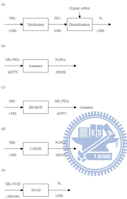
Fig. 1 Flux diagrams of the nitrification-denitrification (a); Anammox (b); SHARON (c);
CANON (d); and SNAD (e). ... 3
Fig. 2 Reactor setup for nitrification process (a) in a single aeration tank (b) extended aeration .... 5
Fig. 3 Typical reactors arrangement in nitrification-denitrification process (a) in Anoxic-aerobic (AO) (b) in aerobic-anoxic (OA) ... 7
Fig. 4 Timelines of discoveries in the fields of ammonium and Anammox. ... 8
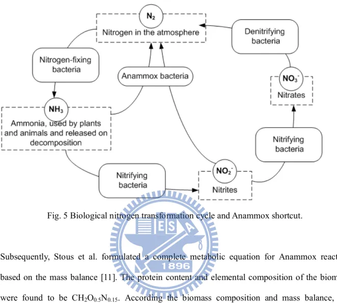
Fig. 5 Biological nitrogen transformation cycle and Anammox shortcut. ... 10
Fig. 6 Mechanism of Anammox. ... 14
Fig. 7 Schematic diagram of the landfill-leachate treatment plant ... 26
Fig. 8 Schematic diagram of SBR ... 30
Fig. 9 Photographs of SBR and PID control system ... 30
Fig. 10 The influent and effluent profile of (a) NH4+-N and (b) NO2--N in the aeration tank... 34
Fig. 10 The influent and effluent profile of (c) NO3--N and (d) COD in the aeration tank. ... 35
Fig. 11 Schematic diagrams showing (a) The leachate characteristics feeding into the aeration tank, and (b) the model based evaluation of SNAD process in the aeration tank ... 38
Fig. 12 (a) Granules in the aeration tank, (b) Anammox granules attached on a carrier, (c) attached growth of Anammox bacteria on the aeration tank wall and (d) Anammox granules in a flask. ... 41
Fig. 13 fluorescence micrographs of bacteria granules collected from the aeration tank (a) DAPI, (b) Amx820 ... 42
Fig. 14 Electrophoresis profiles of the PCR-amplified DNA fragments ... 43
Fig. 15 The result of viability of Anammox bacteria after deep freezing ... 45
ix
Fig. 17 Profiles of total nitrogen and ammonium removal ... 50
Fig. 18 Profiles of influent and effluent COD ... 50
1
Chapter 1 Introduction
Nitrogen removal from wastewater accomplished commonly by biological nitrification followed
by denitrification has raised a lot of attention in the past 100 years. Nitrification repairs abundant
air for oxidation of ammonium to nitrate. On the other hand, huge quantity of organic carbon
source requires for complete denitrification. The requirement of aeration and organic source
enhances the overall operation cost of a wastewater treatment plant. However, the conventional
nitrification followed by denitrification process is not suitable for treating a wastewater
containing high ammonium with low organic carbon in it.
Generally, livestock waste contains high ammonium concentration especially the manure.
Besides, the effluent from anaerobic digesters treating animal carcasses also contains high
ammonium concentration. When the animal carcass is decomposed in the anaerobic digestion,
protein converts to ammonium, accumulates in the reactor and inhibits the activity of
microorganism. This causes the failure of the anaerobic digestion system. Several researchers
attempted to develop a suitable process for treating this high ammonium containing wastewater.
In the last decade, a novel autotrophic nitrogen removal process called “anaerobic ammonium
oxidation” (Anammox) was developed. Moreover, Anammox is recognized as the process
responsible for the completion of nitrogen cycle in the marine/deep-ocean environments.
However, the presence of nitrogen along with organic carbon is toxic to Anammox species.
Therefore, the major focus of this study was to develop an Anammox based system for nitrogen
and organic removal. The objectives of this study were as follows: (i) Enrichment of the
Anammox bacteria. (ii) Analysis of the DNA sequence of Anammox bacteria and comparison
with the DNA sequence in the gene data base and (iii) Development of a stable simultaneous
2
Chapter 2 Literature review
Ammonium disappearing from the ocean has been extensively surveyed in several research labs
[1]. Ammonium been considered an inner compound in the environment, microorganism is
difficult to harvest energy from ammonium degradation. Therefore, ammonium missing in the
ocean was a legend in past 20 years. Some researchers asserted that there must contribute from a
lithotrophic bacterium, which converts ammonium to nitrogen gas directly using proper electron
acceptor. They also calculated the stoichiometric equation to predict the ammonium oxidation
using nitrite as electron acceptor in the anaerobic condition. The stoichiometric equation of the
Anammox reaction illustrated shown in the eq. (1). The free energy of Anammox was -358
kJ/mole. However, the researcher could not identify the microorganism that proceeds anaerobic
ammonium oxidation in water environments. The first identification of the Anammox process
was in the fluidized bed reactor treating fermentation effluent in The Netherlands and it
evidenced the possibility of nitrogen cycle in the marine/deep-sea environments [2].
Consequently, the Anammox process was developed for treating high ammonium and low or
without carbon content wastewater in the recent years.
NH4+ + NO2- N2 + 2H2O (1)
The various commonly adopted ammonium treatment techniques including
nitrification/denitrification, Anammox, SHARON, CANON and SNAD are introduced in Fig. 1
3
Fig. 1 Flux diagrams of the nitrification-denitrification (a); Anammox (b); SHARON (c);
CANON (d); and SNAD (e).
2.1 Nitrification/denitrification
Conventionally, biological nitrogen removal is achieved by the nitrification followed by
denitrification process [4], i.e. (i) aerobic nitrification of ammonium by chemolithoautotrophic
4
denitrification of nitrate to nitrite to gaseous nitrogen by heterotrophic denitrifying bacteria using
organic matter as carbon and energy source.
The complete nitrification reaction is shown in eq. (2). The nitrification includes two steps which
are nitritation and nitratation. Nitritation is transformation of ammonium to nitrite, and nitratation
is transformation of nitrite to nitrate. Nitritation and nitratation are listed in eq. (3) and eq. (4),
respectively. Ammonium is converted to nitrite through ammonium monooxygenase (AMO) [5]
and hydroxylamine oxidoreductase (HAO). The AMO and HAO are the two kinds of enzymes
binding in the bacterial membrane. Hydroxylamine is an intermediate in these two steps. The
relative reaction equation of hydroxylamine production is given in eq. 5, 6 and 7. Adding up of
these equations (eq. (5), (6) and (7)) gives the eq. (3).)
NH3+2O2 NO3-+H++H2O (2)
NH3+1.5O2 NO2-+H++H2O (3)
NO2-+0.5O2 NO3- (4)
NH3+2H++2e-+O2 NH2OH+H2O (5)
NH2OH+H2O HNO2+4H++4e- (6)
2H++0.5O2+2e- H2O (7)
The genes of ammonium oxidizing bacteria (AOB) involving in nitritation are Nitrosomonas,
Ntrosococcus, Nitrosopira, Nitrosovibrio and Nitrosolobus. The second stage of the nitrification
reaction is nitratation which oxidizes of nitrite to nitrate. The complete oxidation of one mole of
ammonium to nitrate consumes two moles of oxygen. The well-known nitrite oxidizing bacteria
(NOB) are Nitrospira, Nitrospina, Nitrococcus and Nitrocystis. In most wastewater treatment
5
The typical reactor used for nitrification shown in Fig. 2 [6]. Most of the nitrification processes
combine BOD removal by combining in sequence. Sometime, an extended aeration is necessary
to proceed nitrification (Fig. 2). While nitrification reaction takes place, it consumes the
alkalinity of wastewater. Therefore, the addition of bicarbonate is the most common operation
strategy for neutralization of produced proton of nitrification from providing necessary alkalinity.
However, the following denitrification reaction could only compensate half of the alkalinity
consumed in nitrification.
Fig. 2 Reactor setup for nitrification process (a) in a single aeration tank (b) extended aeration [6] (a)
6
Nitrification efficiency can be affected by change in pH, temperature, ammonium concentration
and dissolved oxygen (DO) concentration. The optimum pH for nitrifying bacteria growth is
between 7.5 and 8.0. The change in pH value can affect the ammonium and free ammonia (FA)
concentrations. The FA could inhibit nitrifying bacteria activity when the concentration exceeds
150 mg/L. The relationship between ammonium and FA is given in eq. (8).
NH4++OH- NH3+H2O (8)
This equation demonstrates that the decrease in pH could drop-down the FA concentration. When
pH value dropped down to 6.4, all FA will convert to ammonium; when pH value increased up to
9.4, all ammonium converted to FA. Besides, nitrifying bacteria have high affinity to oxygen. In
the DO level between 0.2-0.5 mg/L, nitrifying bacteria (especially AOB) stop forming nitrate.
This shows another possibility of nitrite removal short-cut process. Therefore, nitrite produced
from partial nitrification is able to complete the denitrification. This short-cut process is applied
in simultaneous nitrification-denitrification (SND)[7].
Denitrification reaction reduces the oxidized form of nitrogen, i.e. nitrite or nitrate converted to
nitrogen gas. Organic carbon is used as the electron donor in denitrification. Oxidation of the
organic carbon provides electron for reducing nitrite or nitrate. The end product of denitrification
7
Fig. 3 Typical reactors arrangement in nitrification-denitrification process (a) in Anoxic-aerobic
(AO) (b) in aerobic-anoxic (OA)[6]
The typical denitrification process is always required nitrification process occurred in advanced
shown in Fig. 3 [6]. Two ways could be adopted for developing nitrification followed by
denitrification, i.e. anoxic condition followed by aerobic condition with nitrate recycling back or
aerobic condition followed by anoxic condition.
Nitrous oxide has long atmospheric lifetime approximately 120 years and heat trapping effects
310 times than carbon dioxide on a per molecular basis even higher than methane (23 times than
carbon dioxide). Nitrous oxide is an important greenhouse gas and is produced from various (b)
8
biological sources. When wastewater was decanted into water bodies, nitrous oxide will be
produce due to low DO content.
Denitrifying bacteria could be found in a wide variety of bacteria groups and also widely spread
in water environments. The optimal growth temperature of the denitrifying bacteria is between 30
and 35oC and the pH of range 7.0-8.2 [8]. Denitrifying bacteria are able to consume organic or inorganic carbon for their growth and respiratory process. On the other hand, autotrophic
denitrifying bacteria oxidize hydrogen or reduced sulfur compounds to gain energy and use CO2
as the carbon source. The heterotrophic denitrifying bacteria has ability to utilize organic
compounds such as glycerol, glucose, volatile fatty acids, polyvinyl alcohol and even aromatic
petroleum products as the carbon source [8].
2.2 Anaerobic ammonium oxidation (Anammox)
Denitrification and nitrification processes were found in 1882 and 1890, respectively (Fig. 4)[4].
Over 100 years after its identification of the denitrification process, the nitrogen cycle was
generally believed to be completed.
9
In 1995, Mulder et al. start up a 23-L capacity fluidized bed reactor for treating bakery yeast
wastewater effluent in The Netherland [2]. Mulder et al. found that the nitrate and ammonium
disappear at the same time in the reactor. The nitrification and denitrification could not remove
ammonium only in an anoxic condition except assimilation. Excluding the assimilation,
ammonium disappeared in the reactor, which raised interest by the researchers to advance survey
on it. They recalled an article published in 1977 by Broda et al. which predicted that there are two
lithotroph missing in nature [9]. One lithotroph is as reported to utilize ammonium as electron
donor and nitrite as electron acceptor to form nitrogen gas. The difference between Mulder et al.
and Broda et al. is the electron donor form of utilized in the reaction. Eq. 9 represents the finding
of Mulder et al.
5NH4+ + 3NO3- 4N2 + 9H2O + 2H+ (9)
In eq. (9), the researcher considered that nitrate is used as the electron acceptor instead of nitrite.
Later, Graaf et al. demonstrated the utilization of nitrite as the electron acceptor by tracer
experiment [10]. They designed a fluidized bed reactor introducing 15NH4+ and 14NO2- as tracers.
The end product of the reaction was nitrogen gas composed by 14-15N2. Two nitrogen atoms came
from 15NH4+ and 14NO2-. Graaf et al. successfully demonstrated the anaerobic ammonium
oxidation using nitrite and not by nitrate. In the Mulder et al. study [2], nitrate reduced to nitrite
as the first step and combined ammonium and nitrite to proceed Anammox. Based on the
10
Fig. 5 Biological nitrogen transformation cycle and Anammox shortcut.
Subsequently, Stous et al. formulated a complete metabolic equation for Anammox reaction
based on the mass balance [11]. The protein content and elemental composition of the biomass
were found to be CH2O0.5N0.15. According the biomass composition and mass balance, the
stoichiometry of Anammox is illustrated in eq. (10).
NH4++1.32NO2-+0.066HCO3-+0.13H+ 1.02N2+0.26NO3-+0.066 CH2O0.5N0.15+2.03H2O (10)
Several interesting details can be noticed from the stoichiometry of Anammox. First, the biomass
yield is extremely low, one mole of ammonium only yield 0.066 mole of the biomass. The
extremely low yield of the biomass means the cultivation should spend a long time and also less
11
Anammox reaction. It is a kind of carbon fixation which could avoid global warming. Third,
nitrite is the electron donor and also the electron acceptor. Nitrite reduces to ammonium as
electron acceptor and oxidizes to nitrate to provide energy for assimilation biomass.
Since the Anammox bacteria growth rate is very low, researchers investigated the Anammox
bacteria doubling time to evaluate the performance of Anammox bacteria growth [11-15]. The
doubling time could be assessed by measuring the end product, i.e. nitrogen gas. When
production of nitrogen gas is twice than the initial value, the period could be considered as
doubling time. The first present the doubling time was 30 days [12]. Following the cultivation
improved, the doubling time was shorted from 30 days to 11 days [11].
The bacteria, which found in the fluidized bed reactor in The Netherlands, were confirmed as a
species of planctomycete. Planctomycete has been supposed only by a few organtrophs. Formerly
the planctomycetes were considered to be of limited environmental importance. But this view
changed as a molecular microbial ecology repeatedly providing new evidence that these
bacteria are ubiquitous. Planctomycetes have the single- or double-membrane-bounded
compartments separating their chromosome in the cytoplasm. They lack of peptidoglycan in their
cell wall and are insensitive to ampicillin [16].
To seek out the origin of Anammox bacteria in the biggest anoxic basin, the researchers sampled
sea water at different depth from the “Black Sea” [17]. They found that Anammox bacteria grow
abundantly at the depth of 90 meters in sea. This evidence proved scientists the conversion of
nitrite to nitrogen gas by heterotrophic bacteria and not by the major dinitrogen mechanism. From
the sea water samples (depth of 100 meters), the 16S rRNA gene sequences were performed and
the phylogenetic analysis was carried out. The results showed the Anammox bacteria are related
to member of order Planctomycetales. The Anammox contributes at least 30% of the total
12
nitrogen cycle of the Black Sea. The species found in the Black Sea were identified as
Candidatus Scalindua sorokinii [17]. The mystery of missing nitrogen in the ocean was solved by
investigation in the “Black Sea”. Anammox activity is also responsible for a major part of global
nitrogen turnover [18].
The first discovered and identified Anammox bacteria is Candidatus Brocadia anammoxoidans,
which found in a wastewater treatment plant [11]. Consequently, more Anammox bacteria were
found in the wastewater treatments plants including Candidatus Kuenenia stuttgartiensis [19],
Candidatus Scalindua brodae [20], Candidatus Scalindua wagneri [20], Candidatus
Anammoxoglobus propionius [21], Candidatus Brocadia [22], and Candidatus Jettenia asiatica
[23].
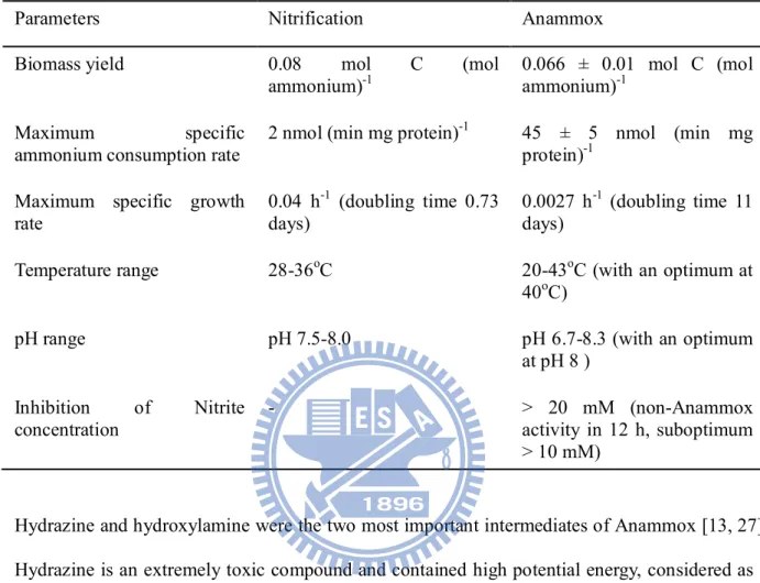
A comparison of nitrification and Anammox is given in Table 1 [13, 24]. The major differences
between nitrification and Anammox are the maximum specific ammonium consumption rate and
growth rate. The ammonium consumption rate of Anammox is 22.5 times more than nitrification,
but 1/100 less growth rate than nitrification. Furthermore, the Anammox cannot tolerate nitrite
concentration over 20 mM for 12 hours.
The optimum Anammox growth temperature is between 20-43oC. For example, a rotating biological contactor (RBC) handling Anammox was successfully operated at temperature 20oC [25]. This result was similar to Isaka et al. where they operated an anaerobic biological filtrated
(ABF) reactor for Anammox [26]. Moreover, many researchers analyzed the marine Anammox
samples, and reported reasonably measurable activities at low temperature. Dosta et al. indicated
that the maximum activity of Anammox was found at 35-40oC; but if the temperature higher than 45oC, an irreversible loss of the activity was observed due to the biomass lysis [24].
13
Table 1 Comparison of nitrification and Anammox
Hydrazine and hydroxylamine were the two most important intermediates of Anammox [13, 27].
Hydrazine is an extremely toxic compound and contained high potential energy, considered as a
rocket fuel. The hydrazine has not been found in microorganism synthesis due to its high toxicity.
This unique compound firstly was found in the Anammox bacteria. The Anammox bacteria have
a special membrane “anammoxosome” to resist the toxicity of hydrazine. The synthesis
pathway of ammonium and nitrite in Anammox was shown in Fig. 6. The electron acceptor nitrite
is reduced to hydroxylamine, which reacted with ammonium as electron donor for forming
hydrazine. The end product of Anammox was oxidation of hydrazine to produce nitrogen gas and
provides four electrons to reduce nitrite for forming hydroxylamine. The oxidation and reduction
enzymes involved in the reaction include hydrazine dydrolase (HH), hydrazine-oxidizing enzyme
Parameters Nitrification Anammox
Biomass yield 0.08 mol C (mol
ammonium)-1
0.066 ± 0.01 mol C (mol ammonium)-1
Maximum specific
ammonium consumption rate
2 nmol (min mg protein)-1 45 ± 5 nmol (min mg protein)-1
Maximum specific growth rate
0.04 h-1 (doubling time 0.73 days)
0.0027 h-1 (doubling time 11 days)
Temperature range 28-36oC 20-43oC (with an optimum at
40oC)
pH range pH 7.5-8.0 pH 6.7-8.3 (with an optimum
at pH 8 ) Inhibition of Nitrite concentration - > 20 mM (non-Anammox activity in 12 h, suboptimum > 10 mM)
14 (HZO), and nitrite-reducing enzyme (NR)[27].
Fig. 6 Mechanism of Anammox [27].
2.3 Single reactor system for high ammonium removal over nitrite (SHARON)
Anammox process requires ammonium and nitrite as shown in the eq. (9). SHARON process was
developed to treat high ammonium concentration wastewater [28-31]. The concept of SHARON
was only 50% of ammonium need to be converted to nitrite (eq. 11). If the wastewater contains
high ammonium and low COD, the combination of SHARON and Anammox is an appropriate
system for ammonium removal.
15
If only 50% ammonium was converted, the wastewater treatment does not need to supply extra
bicarbonate to compensate alkalinity consumption in the nitrification process. The converted
nitrite combined residual ammonium could carry out Anammox. The SHARON process provides
nitrite not nitrate by the operation strategy of controlling sludge retention time (SRT), ammonium
and free ammonia concentration, and dissolved oxygen level. The ammonium oxidizer growth
rate is lower than nitrite oxidizer. A proper SRT could lead AOB to be retained in the reactor and
NOB be washed out from the reactor. The SHARON process was operated in a single reactor
without any sludge retention [29], meaning the SHARON process SRT equals to HRT. This
operation strategy keeps a full-scale SHARON process operation for more than two years.
Furthermore, the reactor temperature was controlled at 35oC, AOB growth rate is higher than NOB [29]. The SHARON process takes advantages of the high temperature, enabling high
specific growth rate, and result in SRT consisting with HRT.
For AOB ammonia is the actual substrate rather than ammonium, and hydroxylamine. But, the
AOB is inhibited by ammonia concentration at 10-100 mg-N/L, higher ammonia toxicity
tolerance than NOB by ammonia concentration at 1-10 mg-N/L. Keeping the higher influent
ammonium concentration could inhibit NOB growth but not AOB. Lower DO concentration,
around 0.2-0.5 mg/L, was another possible condition to stop nitrification at nitrite [7, 32]. For the
oxidation of ammonium to nitrite, 25% oxygen was saved than complete oxidation of ammonium
to nitrate.
The SHARON plus Anammox is an economically feasible process compared to nitrification
followed by denitrification. Only 1.7 kg O2 is needed for 1 kg ammonium removal and no
additional organic carbon source is needed in the SHARON plus Anammox process. In the
16 to nitrate and 4.5 kg COD for denitrification [28].
The disadvantages of the SHARON process are building and energy costs. Beside, two separate
reactors are necessary, i.e. one for partial nitrification and the other for Anammox. Moreover, the
temperature of partial nitrification reactor has to be controlled above 37oC, which could enhance the operation cost.
2.4 Oxygen-limited autotrophic nitrification-denitrification process (OLAND)
In the SHARON process, two reactors are needed to perform partial nitrification and Anammox.
In some countries, land was limited especially in high-density population city. To perform partial
nitrification and Anammox in a single reactor, oxygen-limited autotrophic
nitrification-denitrification (OLAND) process was developed [33]. The advantage of OLAND
was saving half of nitrification/denitrification cost and building only in a set of reactor. Two
group bacteria which are aerobic ammonium oxidizing bacteria (AerAOB) and anaerobic
ammonium oxidizing bacteria (AnAOB) coexist in OLAND process. The AerAOB oxidized
ammonium into nitrite in aerobic condition, which is similar to AOB as illustrated previously,
whereas AnAOB oxidized ammonium into dinitrogen gas in anaerobic condition, which is similar
to Anammox bacteria. The reactions of AerAOB and AnAOB are given in eq. (12) and eq. (13).
1.32NH4++1.98O2 1.32NO2-+1.32H2O+2.64H+ (12)
NH4++1.32NO2-+0.13H+ 0.26NO3-+1.02N2+2.03H2O (13)
However, Anammox requires in an absolutely anaerobic reaction. Only 0.5% air saturation
oxygen level is able to inhibit Anammox activity [34]. The oxygen-limited condition was
17
Anammox was found to survive in the anoxic condition and the low dissolved oxygen could
enrich Anammox bacteria. Therefore, Anammox process can be rewritten as “Anoxic”
ammonium oxidation.
NH4++0.85O2 0.44N2+0.11NO3-+1.08H++1.44H2O (14)
2.5 Completely autotrophic nitrogen removal over nitrite in one single reactor (CANON) The CANON process was first published by Third et al.[35]. A two liters SBR was employed to
treat a synthetic wastewater containing high ammonium concentration and without COD. The
CANON process included nitrifying bacteria and Anammox bacteria for completing the partial
nitrification and Anammox reactions. Nitrifying bacteria was used to convert ammonium to
nitrite, and nitrite was utilized immediately in a single reactor. Well-controlled DO level in the
reactor successfully developed the CANON process. The limitation of CANON was influent
ammonium concentration and DO level in the reactor. If ammonium concentration is higher than
nitrifying bacteria ability, the effluent showed poor ammonium removal. Moreover, higher DO
concentration will complete nitrification resulting in ammonium to nitrate and also inhibit
Anammox activity. The Anammox bacteria is difficult to cultivate due to its slow grow rate.
However, the CANON process could be accelerated (cultivation in 3.5 month) by inoculating the
activated sludge [36]. The well-operated CANON provides a good methodology to get Anammox
bacteria and also provides an efficient choice for ammonium removal with the less land
requirement and less final efforts. However, COD could not be removed in this system. Another
consideration was AOB produce N2O and NO at low oxygen concentration. To clarify this point,
CANON demonstrated negligible N2O production in low oxygen concentration (less than
18
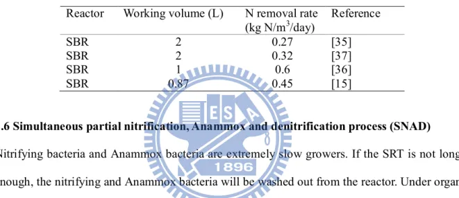
The CANON process was still evaluated in laboratory scale. Table 2 compares the CANON
process operated in different laboratories. The maximum working volume applied in the CANON
system was two liters only, but the maximum nitrogen loading rate reached 0.6 kg N/m3/d. The most common reactor used in the CANON process was the SBR, which could save land
requirement and the capital cost.
Table 2 Comparison of CANON processes
Reactor Working volume (L) N removal rate (kg N/m3/day) Reference SBR 2 0.27 [35] SBR 2 0.32 [37] SBR 1 0.6 [36] SBR 0.87 0.45 [15]
2.6 Simultaneous partial nitrification, Anammox and denitrification process (SNAD)
Nitrifying bacteria and Anammox bacteria are extremely slow growers. If the SRT is not longer
enough, the nitrifying and Anammox bacteria will be washed out from the reactor. Under organic
carbon rich wastewater, heterotrophic bacteria can significant grow. Selection of influent is an
important issue when applying the Anammox process. Alternatively, the development of the
Anammox and denitrification in a single reactor can facilitate the simultaneous nitrogen and
carbon removal. Recently, the simultaneous partial nitrification, Anammox and denitrification
(SNAD) has been developed following the concepts of Anammox and shortcut
nitritation-denitritation (SND)[38-39]. Chen et al. demonstrated the feasibility of the SNAD
process, and this process was successful in operation for an organic loading of up to 0.34 kg
COD/m3/d [38]. This finding widens the application of Anammox for wastewater treatment, i.e. high ammonium and low organic carbon content. Anammox removes 90% ammonium and leaves
19
be supplied for denitrification. Nitrate produced from Anammox could be reduced to nitrite and
nitrite to nitrogen gas through oxidization of organic carbon in the wastewater. The advantage of
SNAD is (i) organic carbon could be removed by heterotrophic bacteria, (ii) and avoid the
toxicity of organic carbon to Anammox. The application of the SNAD species observed in the
full-scale plant to the detailed investigation in laboratory/full scale is still under research.
2.7 Energy capture in nitrogen removal
The microorganism captures energy released from oxidation-reduction reactions [40]. Electrons
are provided from the electron donor and transferred to the intracellular electron carriers. The
electron acceptor receives the electron transported from carriers. The transfer steps have a
free-energy release that the cells capture in the form of energy carriers.
The free energy of nitritation, nitratation, nitrification, denitrification, Anammox including
different electron donor and acceptor are listed in Table 3. The free energy of denitrification is
always higher than nitrification and Anammox even using different electron acceptor. When
influent contains organic compound, the denitrification will start working first. If nitrite and
nitrate coexists in the same environment, denitrifying bacteria consumes the nitrate (free energy
of consuming nitrate is higher than nitrite). After denitrification consumed up the biodegraded
organic compounds, nitrite is better than nitrate for Anammox because more energy could be
gained by Anammox considering nitrite as the electron acceptor. Moreover, the nitritation
harvested more energy than nitratation when oxygen is the electron acceptor. Heterotrophic
20
Table 3 Stoichiometric equation of N-removal processes
Reaction
(donor/acceptor)
Stoichiometric equation Free energy
(kJ/mol) Nitritation (ammonium/oxygen) NH4++1.5O2 NO2-+H2O+2H+ -275 Nitratation (nitrite/oxygen) NO2-+0.5O2 NO3 --74 Nitrification (ammonium/oxygen) NH4++2O2 NO3-+H2O+2H+ -348 Anammox (ammonium/nitrite) NH4++NO2- N2+H2O -358 Anammox (ammonium/nitrate) NH4++0.6NO3- 0.8N2+0.4H++1.8H2O -297 Denitrification (nitrate/methanol) NO3-+0.83CH3OH+H+ 0.5N2+0.83CO2+2.17H2O -545 Denitrification (nitrite/methanol) NO2-+0.5CH3OH+H+ 0.5N2+0.5CO2+1.5H2O -388 Denitrification (nitrate/acetate) NO3-+0.625CH3COO-+H+ 0.5N2+0.625CO2+0.625HCO3-+1.125H2O -498 Denitrification (nitrite/acetate) NO2-+0.375CH3COO-+H+ 0.5N2+0.375CO2+0.375HCO3-+0.875H2O -360 Denitrification (nitrate/glucose) NO3-+0.208C6H12O6+H+ 0.5N2+1.25CO2+1.75H2O -568 Denitrification (nitrite/glucose) NO2-+0.125C6H12O6+H+ 0.5N2+0.75CO2+1.25H2O -402
21
2.8 Anammox application and comparison
Table 4 summarizes the application of the Anammox process so far reported in the literature.
Most of the Anammox processes are applied to laboratory scale reactor, reactor size less than 10
L. Otherwise, one pilot scale [41] and three full scale reactors [39, 42-43] were established
around the world. The synthetic wastewater was popular at the acclimation stage of Anammox
bacteria. Anammox enrichment is easily achieved through inoculating Anammox biomass. Also,
it can reduce the acclimation time. Strous et al. [11] indicating that SBR is a powerful tool for
slow growing Anammox bacteria. Most researchers followed this role for Anammox acclimation.
In Table 4, 15 articles used SBR for experiment set up, and especially one full scale SBR was
applied for landfill-leachate treatment [43].
The suspended growth is most common found in the Anammox enrichment, but the attached
growth was favorable in the recent years. Attached growth could overcome the wash out of
sludge and could retain the Anammox biomass in the reactor. Also, Anammox bacteria prefer to
attached growth on a carrier. Several researches used materials like the fixed bed or biofilm
reactors for Anammox growth. To prevent wash-out the extremely growth Anammox bacteria,
22
Table 4 Summary of Anammox application in literatures
Process Inoculation Reactor (Volume) Medium Reference
Anammox Denitrifying fluidized-bed sludge Fluidized-bed (23 L) Backer’s yeast wastewater [2] Anammox Denitrifying fluidized-bed sludge Serum bottles (0.5 L) Effluent from the denitrifying bed
reactor supplemented with ammonium and nitrate
[10]
Anammox Denitrifying fluidized bed sludge Fluidized bed (2.5 L) Fixed bed (2 L)
Synthetic wastewater and sludge digestion effluent
[44]
Anammox Anammox fluidized bed reactor SBR (15 L) Synthetic [11]
SHARON _____ CSTR (1.5 L) Effluent of the sludge digestion [29]
Anammox Anammox biomass Serum bottles (0.05 L)
Biofilm reactors (0.33 L)
Synthetic [45]
CANON Anammox biomass-SBR SBR (2 L)
Chemostat (2 L)
Synthetic [35]
Anammox Anammox biomass SBR (2 L) Synthetic [46]
Anammox Denitrification process sludge CSTR (2.5 L) Synthetic [47]
CANON Anammox biomass-SBR SBR (2 L) Synthetic [37]
Partial nitrification followed Anammox
Activated sludge CSTR (2100 L) Real wastewater [41]
Anammox and
denitrification
Activated sludge Serum bottles (0.5 L) Poultry manure [48]
Anammox Denitrification process sludge CSTR (2.5 L and 14 L) Synthetic [49]
Anammox and CANON
Anammox biomass-SBR Gas-lift (1.8 L) Synthetic [50]
Anammox Anammox biomass Gas-lift (3 L)
SBR (1 L)
Synthetic [51]
23 OLAND Nitrifying bacteria and Anammox
biomass
MBR (1.5 L) Digested sludge dewatering wastewater
[53]
CANON Activated sludge + RBC sludge SBR (3 L) Synthetic [54]
CANON Anammox biomass RBC (50 L)
Fixed-film bioreactor (8.1 L)
Synthetic [55]
CANON Activated sludge Modified SBR (1 L) Synthetic [36]
SHARON Biological nitrogen removal reactors SBR (1 L) Chemostat (4 L)
Anaerobic sludge reject water [31]
Anammox Anammox biomass SBR (2.5 L) Synthetic [56]
Anammox Activated sludge Continuous up-flow
reactor (0.5 L)
Synthetic [57]
Anammox Anammox biomass-SBR MSBR (5 L) Synthetic [14]
DEAMOX Expanded granular sludge bed UASB (2.53 L) Backer’s yeast wastewater [58]
Anammox Anammox biomass SBR (1 L) Synthetic [59]
Anammox Anammox biomass Glass bottle (0.7 L) Deorderization wastewater [60]
Anammox Mixed culture (sludge of UASB, activated sludge, anaerobic sludge digestion)
SBR (7 L) Synthetic [61]
Anammox Nitrifying sludge and Anammox biomass
Gas-lift (70000 L) [42]
Anammox Sludge from 11 different wastewater treatment plants
Up-flow fixed-bed glass biofilm column (0.8 L)
Synthetic [62]
Anammox Anammox biomass SBR (500000 L) Reject water from digested-sludge
dewatering
[43]
SNAD Anaerobic granule sludge UASB (0.2 L) Synthetic [63]
CANON Anammox biomass SBR (1.87 L) Synthetic [15]
SNAD Anammox biomass Nonwoven RBC (1.2 L) Synthetic [38]
SNAD Activated sludge Continuous flow
(400000 L)
Landfill-leachate [39]
SNAD SNAD sludge SBR (18 L) Synthetic [64]
24
2.9 Summary
The various nitrogen removal methods are introduced in the previous sections. The optimum
choice depends on the purpose and need. The wastewater characteristics, operational cost and
maintaining cost should be well-evaluated before developing a method. Schmidt et al.
summarizes some nitrogen treatment methods as showed in Table 5 [3]. Besides, the SNAD
process is also listed in this table to compare with other nitrogen treatment methods.
Table 5 Summary of biological nitrogen removal processes [66]
Conventional nitrification denitrification
Anammox SHARON CANON/OLAND SNAD
AOB exist absent exist exist exist
NOB exist absent absent exist exist
Anammox absent exist exist exist exist
Denitrifying bacteria
exist absent absent absent exist
Ammonium loading (kg N/m3/d) 2-8 10-20 0.5-1.5 2-3 0.5-0.7 N-removal efficiency 95% 90% 90% 90% 99% Application status
established Full scale plant
Full scale plant
Laboratory Full scale plant
Investment costs
medium low medium medium medium
Operational costs
25
Chapter 3 Materials and Methods
3.1 Description of the full-scale landfill-leachate reactor
Anammox bacteria could be enriched from different sludges, sediments and soils. So far,
Anammox bacteria have been found in high ammonium containing wastewater. A sludge sample
was collected from an anaerobic digestion unit treating a pig waste for enriching Anammox
bacteria. For the cultivation of Anammox bacteria, the landfill-leachate containing high
ammonium and low COD is suitable. To collect and enrich Anammox bacteria from the
landfill-leachate, a full-scale landfill-leachate treatment plant which is located in Taiwan was
identified. This treatment plant is has been operating since 2006 with an average flow of 304
m3/d. The landfill site was used to dispose domestic waste from 1992 to 2005. The schematic diagram of the treatment plant is shown in Fig. 7 and the influent and effluent qualities from the
aeration tank (the SNAD process) are summarized in Table 6. The phenomena of simultaneous
partial nitrification, denitrification and Anammox occurs in two parallel aeration tanks (15.6 m L
by 4.1 m W by 3 m D) corresponding to a working volume of 384 m3 and operating at a hydraulic retention time (HRT) of 1.26 d with . The sludge retention time (SRT) in the aeration tank was
maintained between 12 and 18 d. The concentrations of the mixed liquor suspended solids
(MLSS) and mixed liquor volatile suspended solids (MLVSS) in the aeration tanks were 2110
and 1506 mg/L, respectively. The aeration tanks were equipped with a couple of fine bubble
tubular diffusers. The DO concentration in the reactor was maintained at approximately 0.3 mg/L,
which facilitated the co-existence of ammonium oxidizing bacteria (AOB), Anammox bacteria
and denitrifiers. The pH in the aeration tanks was around 7.4 and the temperature was found to be
fluctuated under the influence of ambient temperature within 30-33oC during the course of the sample collection process (October – December, 2008). Influent and effluent samples were
26
collected from the aeration tanks on a regular basis and analyzed in both the on-site lab in the
landfill-leachate treatment plant and the lab in Institute of Environmental Engineering, NCTU,
Taiwan. The average COD, ammonium and nitrate concentrations at the upstream end of the
bioreactor, i.e., influent, were 554, 634 and 3 mg/L, respectively; whereas, nitrite concentration
was below the detectable limit at all times.
Collection tank Reservoir Aeration tank Reverse Osmosis Air stripping Secondary clarifier Influent
Effluent Equalization tank
Waste sludge Recycle sludge Flush water collection tank Return to landfill Aeration tank Flush water Supernatant Leachate Sludge
Fig. 7 Schematic diagram of the landfill-leachate treatment plant
Table 6 Main characteristics of leachate
Parameters Influent to aeration tank Effluent off aeration tank
pH 7.9 7.3 TS, mg/L 2610±21.8 1970±21.8 VS, mg/L 554±26.8 448±26.8 COD, mg/L 554, mg/ 399, mg/ BOD, mg/L 57.3±0.72 8.70±0.1 NO2--N, mg/L ND<0.0 0.40.0/ NO3--N, mg/L 3.0 mg/ 22.7mg/L3 NH4+-N, mg/L 634 mg/ 126 mg/L TKN, mg/L 676±55.9 114±9.4 PO43-, mg-P/L 3.80±0.50 1.75±0.66 TOC, mg-C/L 159±0.0 70.2±0.0
27
3.2 Polymerase chain reaction (PCR) and qPCR
The total genomic DNA present in the samples was extracted using the UltraClean Microbial
DNA isolation Kit (MO BIO Laboratories, USA). The 16S rDNA sequences were amplified from
the genomic DNA by PCR using 11f (5’-GTTTGATCCTGGCTCAG-3’) and 1512r
(5’-GGYTACCTTGTTACGACTT-3’) oligonucleotide primers [67]. The thermal cycling
consisted of 10 min at 94 oC followed by 35 cycles each of 90 sec at 94oC, 45 sec at 52oC, 120 sec at 72oC and ended by an additional 10 min at 72oC. The nucleotide sequence of PCR products were determined using the BigDye terminator cycle sequencing kit (Applied Biosystems, USA).
The resulting sequences were used to do nucleotide-nucleotide blast search through the National
Center for Biotechnology Information (NCBI). To amplify 16S rDNA of Anammox bacteria,
PCR was performed using an oligonucleotide primer pair, 16S-1
(5’-AGTGGCGAAAGGGTGAGTAA-3’) and 16S-2 (5’-GGTTACCTTGTTACGACT-3’)
[47](referred as primer III) with a thermal cycling of 10 min at 94oC followed by 40 cycles each of 15 sec at 94oC, 2 sec at 50oC, 60 sec at68oC and ended by an additional 10 min at 72oC.
3.3 Fluorescence in situ hybridization (FISH)
The 16S rRNA-targeted oligonucleotide probe used in this study was Amx820 [68] for Anammox
bacteria. The probe was synthesized and directly labeled with fluorescein isothiocyanate (FITC)
at the 5’ end. In situ hybridization was performed according to the procedure described by Amann
et al. [69]. A 100X objective Olympus BX51 microscope (Olympus Optical Co., Japan) fitted
with a mercury bulb and blue, green and red filter sets was used for observing the slides. The
photomicrograph was made using an Olympus U-CMAD 3 camera (Olympus Optical Co., Japan)
28
3.4 Lab scale SNAD system and operation strategy
The SNAD process was developed in a SBR with a working volume of 2.5 L and using the
inoculated biomass from the full-scale landfill-leachate treatment plant in Taiwan [39]. The
schematic diagram and photographs of SBR are shown in Fig. 8 and Fig. 9, respectively. The
reactor was set by using a 3-L beaker keeping inside an incubator and equipped with influent and
effluent pumps, pH, ORP and DO probes. An agitator was installed in the reactor with two blades
and controlled the rotating speed at 100 rpm for mixing the mixed liquor completely. The SBR
was operated in a cycle of 24 h with 12 h influent/reaction, 11.5 h reaction, 0.25 h settling and
0.25 h decanting. The HRT of the reactor was maintained at 2.5 d by feeding the reactor at a flow
rate of 1 L influent per day. The SBR was operated in such a way to maintain a MLSS
concentration of around 5,000 mg/L. The SRT of the SBR was maintained at infinitive to retain
the slow growing Anammox bacteria. A fine bubble form diffuser was installed in the reactor and
was cleaned by acid solution for a period to remove the attached biomass. In addition, a DO
control system was installed in the SBR to supply/adjust the desired DO level precisely. The DO
control system composes of a DO meter, air flow valve and PID controller. The application of the
DO control system is useful to maintain a DO level in the SBR as accurate as ~0.1 mg/L, which
is also helpful for preventing the rapid nitrite accumulation and nitrite oxidation to nitrate.
Throughout the course of the study period, the SBR was operated at 35oC and the reactor contents are mixed uniformly using an agitator.
The real-time landfill-leachate was used as the feed for the SBR. The real-time landfill-leachate
was collected four times (Stages I to IV) in a calendar year to monitor/quantify the real
wastewater influent, stored in a refrigerator and used for the SBR study. The SBR reactor was
operated continuously using the landfill-leachate samples collected at various stages, i.e. stage-I
29
composition of the landfill-leachate wastewater at various stages (I to IV) is shown in Table 7. In
the first stage, the influent ammonium concentration of the leachate was 295 mg/L corresponding
to a C/N ratio of 0.85. However, the influent ammonium concentration increased gradually in the
subsequent samplings with a maximum of 700 mg/L in the stage IV. On the other hand, the
COD/TN ratio was maintained as constant (0.85) in the stages I and II, decreased gradually in the
stage III (0.55) and again increased in the stage IV (0.71). This data showed that NH4+-N and
COD concentrations fluctuated drastically in the study period. However, the nitrite and nitrate
concentrations in the leachate were close to zero (0-4 mg/L) irrespective of the sampling time.
Table 7 the composition of the real-time landfill-leachate wastewater at various stages
Stages Time of operation (d) NH4+-N (mg/L) NO2--N (mg/L) NO3--N (mg/L) BOD (mg/L) COD (mg/L) COD/TN (BOD/TN) ratio OLR (mg-COD/L/d) NLR (mg-N/L/d) I 38 295 2 0 88 250 0.85 (0.35) 100 118 II 16 590 4 0 164 500 0.85 (0.33) 200 236 III 93 660 0 0 155 365 0.55 (0.42) 146 264 IV 44 700 0.5 1.8 178 500 0.71 (0.36) 200 280
30 DO monitor O2 valve DO probe aerator effluent influnet
Recorder (air flow rate, DO, pH and ORP)
Influent pump
effluent pump agitator
Fig. 8 Schematic diagram of SBR
31
3.5 Anammox bacteria preservation and viability test
Anammox bacteria collected from the landfill-leachate treatment plant was flushed twice using
degassed synthetic medium. The Anammox granules were ground by tissue grinder (Knotes,
USA). The ground sample was filled up using a cryogenic vial and added with glycerin. The
cryogenic vial was frozen at -80oC, which preserved of Anammox bacteria.
After removal of the cryogenic vial from freezing compartment, the frozen vial was put in a water
bath at 37oC. When the vial temperature reached 37oC, it was centrifuged for 10 min at 125x g. The outside part of the vial was disinfected by 70% ethanol before moving to an anaerobic glove
box. Then, the cap of the vial was opened and the supernatant of the vial in the anaerobic glove
box was removed. The Anammox biomass in the vial was moved to a 100-mL anaerobic tube
filling with the culture medium [12] shown in Table 8. The final volume of anaerobic tube was 50
mL.
Table 8 Culture medium compositions
Medium
Composition mg/L Trace element mg/L
(NH4)2SO4 42 EDTA 1500 NaNO2 15 ZnSO4 7H2O 430 KHCO3 1250 CoCl2 6H2O 240 NaH2PO4 50 MnCl2 4H2O 990 CaCl2˙2H2O 200 CuSO4 5H2O 250 MgSO4˙7H2O 200 NaMoO4 2H2O 220 FeSO4 14 NiCl2 2H2O 190 EDTA 18.6 NaSeO4 10H2O 210 H3BO4 14
Trace element 1 (mL/L) NaWO4 2H2O 50
The anaerobic tube was incubated in an incubator controlling temperature at 35oC for 24 h. After incubation, the sample was put under UV exposure with a wavelength between 350 nm and 600
32
indicated that Anammox bacteria show a maximum peak between 400-410 nm [24]. Meanwhile,
520 and 550 nm adsorption signals were also indicate the activity of the Anammox bacteria
[70-71].
3.6 Analytical techniques
The pH and ORP in the SBR were recorded using the digital pH and ORP meters (Suntex PC320,
Taiwan), respectively. All chemical analyses were performed according to the Standard Methods
[72]. Ammonium and nitrite concentrations were determined by the colorimetric method, whereas
nitrate was measured spectrophotometrically. The organic matter content of the wastewater was
analyzed according to the Standard Methods and expressed as COD. Moreover, the solids in the
SBR including suspended solid (SS), volatile suspended solid (VSS), MLSS and MLVSS were
33
Chapter 4 Results and Discussion
4.1 Performance of landfill-leachate treatment plant
Fig. 10 (a-c) shows the influent and effluent concentrations of nitrogenous compounds in the
aeration tank from the full-scale landfill-leachate treatment plant. The nitrite concentration in the
aeration tank influent is below the detectable limit. However, a decrease in ammonium
concentration with simultaneous increase nitrate concentration is observed in the aeration tank.
This implies a conventional chemolithoautotrophic oxidation of ammonium to nitrite by AOB
and subsequently from nitrite to nitrate by nitrite oxidizing bacteria (NOB). The low DO
concentration in the aeration tank may inhibit the microbial activity so that a complete
nitrification is not observed. Alternatively, ammonium concentration can be consumed by
Anammox bacteria. Thermodynamically, Anammox is favorable at two molar ratios of
ammonium to nitrite, i.e., 1:1 and 1:1.67 [2, 9, 73]. When the Anammox becomes predominant,
two interlinked processes can be hypothesized to occur: (i) partial nitrification, i.e., ammonium to
nitrite by the AOB, followed by (ii) Anammox. Oxygen limited conditions can provide an
adequate environment for a stable interaction between Nitrosomonas-like aerobic microorganism
and Planctomycete-like anaerobic bacteria [38, 41, 74]. Moreover, the concept of CANON
process is also the combination of partial nitrification and Anammox in a single reactor. Kuai and
Verstreate [33] and Hippen et al. [75] used the concepts of CANON process in OLAND and
aerobic deammonification processes, respectively [73]. Therefore, AOB is believed to oxidize
ammonium to nitrite initially in the aeration tank by consuming DO to create an anaerobic/anoxic
microenvironment. The produced nitrite is utilized along with the remaining ammonium by the
Anammox bacteria to be converted into nitrogen gas in the anaerobic environment [19]. However,
34 in Anammox are highly complicated.
10/280 11/4 11/11 11/18 11/25 12/2 12/9 250 500 750 1000 Influent Effluent 10/280 11/4 11/11 11/18 11/25 12/2 12/9 25 50 75 100 Influent Effluent
Fig. 10 The influent and effluent profile of (a) NH4+-N and (b) NO2--N in the aeration tank. (Note:
Solid and dash lines indicate the average of influent and effluent concentrations, respectively.) (a) N H4 + -N c o n c e n tr a ti o n , m g /L
Date of sampling in the year 2008
Date of sampling in the year 2008
N O2 - -N c o n ce n tr a ti o n , m g /L (b)
35 10/280 11/4 11/11 11/18 11/25 12/2 12/9 20 40 60 80 100 Influent Effluent 10/280 11/4 11/11 11/18 11/25 12/2 12/9 250 500 750 1000 Influent Effluent
Fig. 10 The influent and effluent profile of (c) NO3--N and (d) COD in the aeration tank. (Note:
Solid and dash lines indicate the average of influent and effluent concentrations, respectively.) Date of sampling in the year 2008
N O3 - -N c o n c e n tr a ti o n , m g /L (c) C O D , m g /L (d)
36
The maximum removal efficiencies of total nitrogen (TN) and ammonium in the aeration tank
were approximately 76% and 80%, respectively. Interestingly, a decrease in COD was also
observed (Fig. 10 (c)) in the aeration tank with simultaneous reduction of the ammonium
concentration. The COD is used by heterotrophic bacteria as carbon and energy source during
denitrification, whereas nitrite and/or nitrate are used as electron acceptors. The affinity between
nitrite and Anammox bacteria is much higher than that between nitrite and denitrification bacteria
[76]. Therefore, nitrite produced from partial nitrification could be consumed by the Anammox
bacteria immediately. Thus, the majority of nitrite is consumed by the Anammox bacteria, and the
nitrate produced from Anammox is consumed by heterotrophic denitrification with simultaneous
COD removal. Subsequently, the nitrite produced from partial nitrification is also consumed by
Anammox bacteria. Denitrification and Anammox occur under anoxic condition in the presence
of electron donors. Several researchers reported the possibility of denitrification/partial
denitrification and Anammox in one reactor [48, 73, 77]. Moreover, Anammox was first
identified in a methanogenic reactor [2].
Recently, Chen et al. identified the SNAD process for the simultaneous nitrogen and COD
removal using a small scale non-woven rotating biological contactor (RBC). The mechanism of
SNAD is believed to account for the simultaneous removals of nitrogen and COD in the aeration
tank of the landfill-leachate treatment plant. The stoichiometric relationship of partial nitrification,
Anammox and denitrification are used to estimate the quantities of nitrogen and COD consumed
in the treatment plant. The performance of the SNAD system and other partial nitrification
37
Table 9 Comparisons of Anammox applied full-scale wastewater treatment plants
Process Location Volume (L) Target NLR (g/L/d) References SHARON+ Anammox The Netherlands 70,000 Rejection water of digested sludge dewatering 10 Abma et al., 2007
DEMON Australia 500,000 Real-time wastewater 0.68 Wett, 2007 SNAD Taiwan 384,000 Landfill-leachate 0.5 Wang et al.,
2010
4.2 Model based evaluation of partial nitrification, Anammox and denitrification
If the aeration tank is considered as a black box (Fig. 11 (a)), the quantity of nitrogen consumed
by partial nitrification, Anammox and denitrification can be modeled based on the stoichiometric
equations. The monthly average data are used for modeling and the outcomes are shown in Fig.
11 (b).
The model assumes the stoichiometric relationships for several biological activities in the
aeration tanks: (i) partial nitrification occurs in the aeration tank followed by Anammox and
denitrification, (ii) in partial nitrification, the molar ratio of ammonium to nitrite is 1:1, (iii) the
molar ratio of ammonium to nitrite consumes in Anammox is 1:1.32 and produces 0.26 mol of
nitrate, subsequently that is utilized in denitrification, (iv) the organic matter composition of the
influent is C1.6H3.3O1.1N0.02 (based on the elemental analysis of the landfill-leachate) and therefore,
(v) theoretically, denitrification can utilize 1 mol of nitrate per mol of COD consumption as
shown in eq. 15.
38 NH4+-N (634 mg L-1) Remaining NH4+-N (219 mg L-1) Remaining NO2--N (289 mg L-1) ANAMMOX 1NH4+-N: 1.32NO2--N (219: 289 mg L-1) Partial nitrification NO3--N (57 mg L-1) COD in influent (554 mg L-1) 0.26 NO3 -N2 gas Denitrification 1 g of COD: 0.38 g of NO3--N HCO3 -p H a d ju st m e n t Effluent NH4+-N = 126 mg L-1 NO3--N = 0 mg L-1 COD = 399 mg L-1
Fig. 11 Schematic diagrams showing (a) The leachate characteristics feeding into the aeration
tank, and (b) the model based evaluation of SNAD process in the aeration tank 1. Partial nitrification
(1 NH4+ produces 1 NO2-)
2. ANAMMOX
(1 NH4+ consumes 1.32 NO2- and produces 0.26 NO3-)
3. Denitrification (1 COD consumes 0.38 NO3-) Influent: NH4+-N 634±143 mg/L NO2--N not detectable NO3--N 3.0±0.0 mg/L COD 554±96.9 mg/L Effluent: NH4+-N 126±57.1 mg/L NO2--N 5.9±12.6 mg/L NO3--N 22.7±12.3 mg/L COD 399±59.2 mg/L (a) (b)
39
It can be seen from Fig. 11 (b) that based on the stoichiometric model the combined partial
nitrification and Anammox could remove about 68% of TN from the aeration tank. On the other
hand, heterotrophic denitrification is responsible for the removal of 8% TN and 23% COD in the
aeration tank. Whereas, the total COD removal in the aeration tank is 28%, i.e., COD reduced
from 554 to 399 mg/L (Fig. 11 (b)). The gap between the COD removals (23%) could be due to
the COD consumption by the other heterotrophic organisms in the aeration tank. Denitrification
and Anammox produce alkalinity to maintain at a stable pH range while partial nitrification
occurs. The stoichiometric calculations of ammonium, nitrate and nitrite concentrations shown in
Fig. 11 (b) are in a good match with the corresponding the experimental results.
4.3 Observation of microbial community
At the time of sampling collection for biotechnological analysis, several images of the bacterial
granules existed in the aeration tank were captured (Fig. 12). The images show the red granules,
which were found to be in Anammox reactors typically [43, 62, 78]. The average diameter of
Anammox granules found in the field was 5 mm as shown in Fig 12 (d). Compared to the
diameter of granules in the first full-scale Anammox reactor, 1.4 mm granules were found [79].
Another granule formation (diameter 2.5 mm) was found in a UASB, which was inoculated with
activated sludge [65]. Subsequently, the FISH analysis confirmed the occurrence of Anammox
bacteria in the aeration tank (Fig. 13). The total bacteria containing DNA was stained with the
DAPI that represents roughly all bacteria as shown in Fig. 13 (a). The Fig. 13 (b) represented the
Anammox bacteria hybridized with probe Amx820. Through the comparison of Fig. 13 (a) and
(b), the major population in the granule was Anammox bacteria. The morphology of Anammox
40 (a)
![Fig. 2 Reactor setup for nitrification process (a) in a single aeration tank (b) extended aeration [6] (a)](https://thumb-ap.123doks.com/thumbv2/9libinfo/8437621.181637/16.892.124.761.476.1042/reactor-setup-nitrification-process-single-aeration-extended-aeration.webp)
![Fig. 3 Typical reactors arrangement in nitrification-denitrification process (a) in Anoxic-aerobic (AO) (b) in aerobic-anoxic (OA)[6]](https://thumb-ap.123doks.com/thumbv2/9libinfo/8437621.181637/18.892.134.759.162.699/typical-reactors-arrangement-nitrification-denitrification-process-anoxic-aerobic.webp)
![Fig. 4 Timelines of discoveries in the fields of ammonium and Anammox [4].](https://thumb-ap.123doks.com/thumbv2/9libinfo/8437621.181637/19.892.134.808.802.1013/fig-timelines-discoveries-fields-ammonium-anammox.webp)
![Fig. 6 Mechanism of Anammox [27].](https://thumb-ap.123doks.com/thumbv2/9libinfo/8437621.181637/25.892.122.764.232.758/fig-mechanism-of-anammox.webp)

![Table 5 Summary of biological nitrogen removal processes [66]](https://thumb-ap.123doks.com/thumbv2/9libinfo/8437621.181637/35.892.124.816.451.1088/table-summary-biological-nitrogen-removal-processes.webp)
![HPSH [ 氧化數平衡反應式係數 ]](data:image/gif;base64,R0lGODlhAQABAIAAAP///wAAACH5BAEAAAAALAAAAAABAAEAAAICRAEAOw==)